Page 781 of 3745
BL-272
< SERVICE INFORMATION >
BODY REPAIR
6. 1st roof rail assembly
7. Front roof rail assembly
8. Sun roof assembly
9. Front roof rail assembly (if equipped with sunroof)
10. Roof side rail reinforcement (RH & LH)
11. Inner center pillar (RH & LH)
12. Hood assembly
13. Center pillar reinforcement (RH & LH)
14. Front pillar inner (RH & LH)
15. Front pillar upper reinforcement (RH & LH)
16. Front pillar lower reinforcement (RH & LH)
17. Fender (RH & LH)
18. Side body (RH & LH)
19. Side body assembly (RH & LH)
20. Outer sill (RH & LH)
21. Outer sill reinforcement (RH & LH)
22. Front door assembly (RH & LH)
23. Outer front door panel (RH & LH)
24. Outer rear door panel (RH & LH)
25. Rear door assembly (RH & LH)
26. Rear fender (RH & LH)
27. Rear fender assembly (RH & LH)
28. Rear fender corner (RH & LH)
29. Rear fender extension (RH & LH)
30. Rear combination lamp base (RH & LH)
31. Rear pillar inner reinforcement (RH & LH)
32. Rear wheel housing outer (RH & LH)
33. Rear wheel housing inner (RH & LH)
34. Rear spring base assembly (RH & LH)
35. Rear seatback hinge bracket (RH & LH)
36. Rear seatback catch bracket (RH & LH)
37. Rear pillar inner (RH & LH)
38. Rear roof rail reinforcement (RH & LH)
39. Rear roof rail brace (RH & LH)
40. Rear panel
41. Rear bumper fascia lower bracket
42. Rear bumper fascia upper bracket
43. Rear bumper fascia center bracket
44. Rear panel assembly
45. Back door assembly
Revision: January 20102010 Versa
Page 782 of 3745
BODY REPAIRBL-273
< SERVICE INFORMATION >
C
DE
F
G H
J
K L
M A
B
BL
N
O P
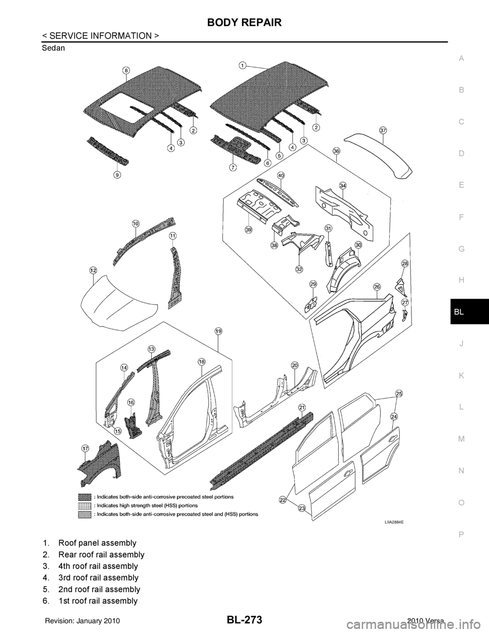
Sedan
1. Roof panel assembly
2. Rear roof rail assembly
3. 4th roof rail assembly
4. 3rd roof rail assembly
5. 2nd roof rail assembly
6. 1st roof rail assembly
LIIA2884E
Revision: January 20102010 Versa
Page 783 of 3745
BL-274
< SERVICE INFORMATION >
BODY REPAIR
7. Front roof rail assembly
8. Sun roof assembly
9. Front roof rail assembly (if equipped with sunroof)
10. Roof side rail reinforcement (RH & LH)
11. Inner center pillar (RH & LH)
12. Hood assembly
13. Center pillar reinforcement (RH & LH)
14. Front pillar inner (RH & LH)
15. Front pillar upper reinforcement (RH & LH)
16. Front pillar lower reinforcement (RH & LH)
17. Fender (RH & LH)
18. Side body (RH & LH)
19. Side body assembly (RH & LH)
20. Outer sill (RH & LH)
21. Outer sill reinforcement (RH & LH)
22. Front door assembly (RH & LH)
23. Outer front door panel (RH & LH)
24. Outer rear door panel (RH & LH)
25. Rear door assembly (RH & LH)
26. Rear fender (RH & LH)
27. Rear fender corner (RH & LH)
28. Rear combination lamp base (RH & LH)
29. Rear wheel housing front extension (RH & LH)
30. Rear wheel housing outer (RH & LH)
31. Rear pillar inner reinforcement (RH & LH)
32. Rear body side inner (RH & LH)
33. Rear wheel housing inner (RH & LH)
34. Rear panel assembly
35. Rear bumper fascia upper bracket
36. Rear bumper fascia center bracket
37. Trunk lid assembly
38. Parcel shelf side (RH & LH)
39. Parcel shelf assembly
40. Rear waist panel
41. Rear bumper fascia lower bracket
Corrosion ProtectionINFOID:0000000005396720
DESCRIPTION
To provide improved corrosion prevention, the following anti-corrosive measures have been implemented in
NISSAN production plants. When repairing or replacing body panels, it is necessary to use the same anti-cor-
rosive measures.
ANTI-CORROSIVE PRECOATED STEEL (GALVANNEALED STEEL)
Revision: January 20102010 Versa
Page 786 of 3745
BODY REPAIRBL-277
< SERVICE INFORMATION >
C
DE
F
G H
J
K L
M A
B
BL
N
O P
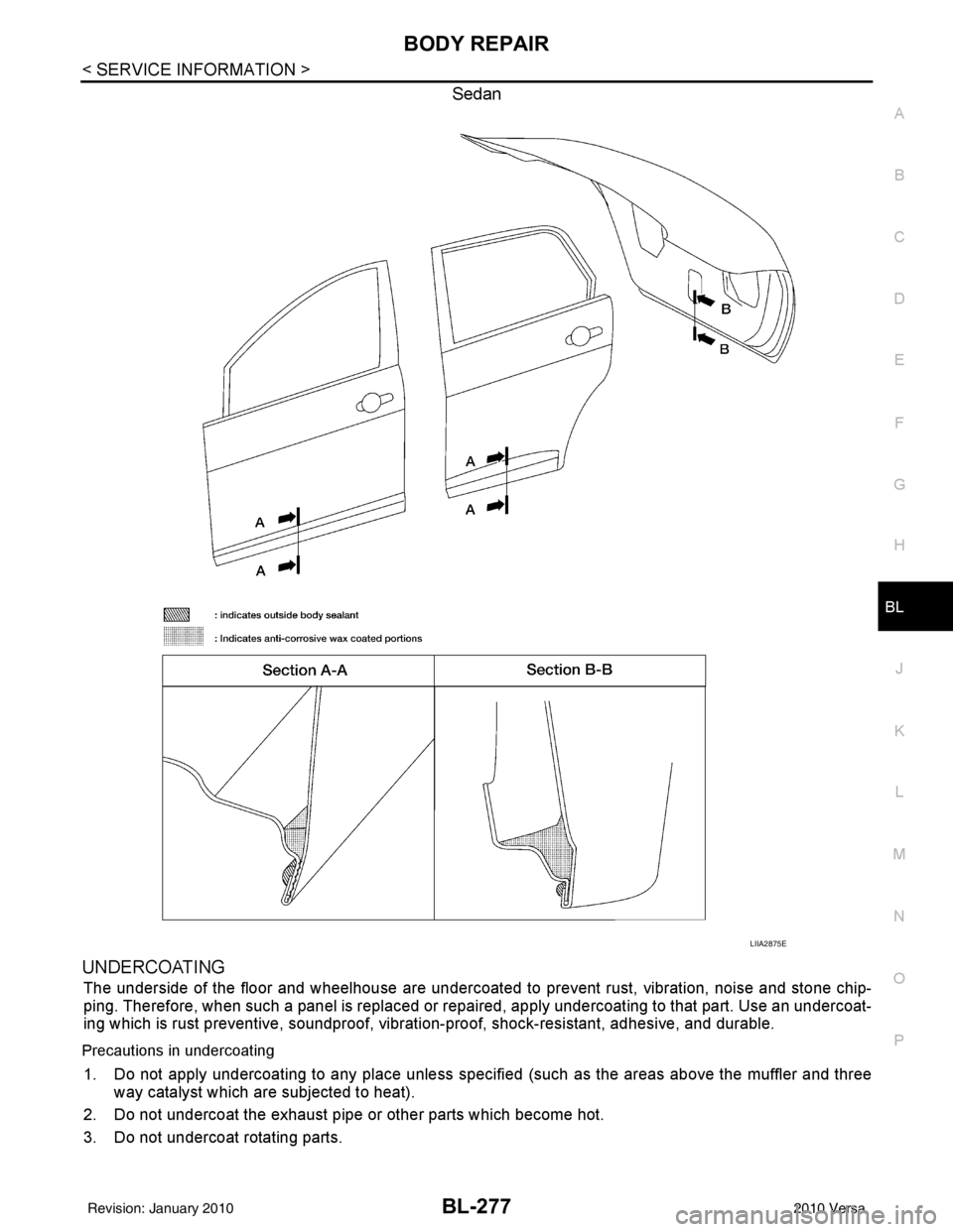
Sedan
UNDERCOATING
The underside of the floor and wheelhouse are undercoated to prevent rust, vibration, noise and stone chip-
ping. Therefore, when such a panel is replaced or re paired, apply undercoating to that part. Use an undercoat-
ing which is rust preventive, soundproof, vibr ation-proof, shock-resistant, adhesive, and durable.
Precautions in undercoating
1. Do not apply undercoating to any place unless specif ied (such as the areas above the muffler and three
way catalyst which are subjected to heat).
2. Do not undercoat the exhaust pipe or other parts which become hot.
3. Do not undercoat rotating parts.
LIIA2875E
Revision: January 20102010 Versa
Page 816 of 3745
BODY REPAIRBL-307
< SERVICE INFORMATION >
C
DE
F
G H
J
K L
M A
B
BL
N
O P
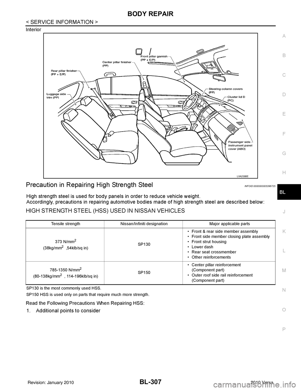
Interior
Precaution in Repairing High Strength SteelINFOID:0000000005396725
High strength steel is used for body panels in order to reduce vehicle weight.
Accordingly, precautions in repairing automotive bodies made of high strength steel are described below:
HIGH STRENGTH STEEL (HSS) USED IN NISSAN VEHICLES
SP130 is the most commonly used HSS.
SP150 HSS is used only on parts that require much more strength.
Read the Following Precautions When Repairing HSS:
1. Additional points to consider
LIIA2588E
Tensile strength
Nissan/Infiniti designation Major applicable parts
373 N/mm
2
(38kg/mm2 ,54klb/sq in) SP130• Front & rear side member assembly
• Front side member closing plate assembly
• Front strut housing
• Lower dash
• Rear seat crossmember
• Other reinforcements
785-1350 N/mm
2
(80-138kg/mm2 , 114-196klb/sq in) SP150• Center pillar reinforcement
(Component part)
• Outer roof side rail reinforcement (Component part)
Revision: January 20102010 Versa
Page 821 of 3745
BL-312
< SERVICE INFORMATION >
BODY REPAIR
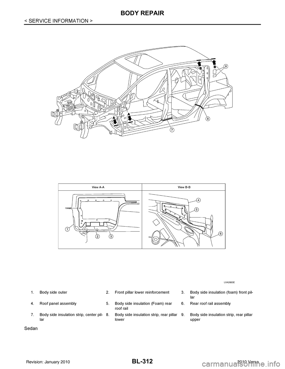
Sedan
1. Body side outer2. Front pillar lower reinforcement 3. Body side insulation (foam) front pil-
lar
4. Roof panel assembly 5. Body side insulation (Foam) rear
roof rail 6. Rear roof rail assembly
7. Body side insulation strip, center pil- lar 8. Body side insulation strip, rear pillar
lower 9. Body side insulation strip, rear pillar
upper
LIIA2665E
Revision: January 20102010 Versa
Page 822 of 3745
BODY REPAIRBL-313
< SERVICE INFORMATION >
C
DE
F
G H
J
K L
M A
B
BL
N
O P
Replacement OperationINFOID:0000000005396727
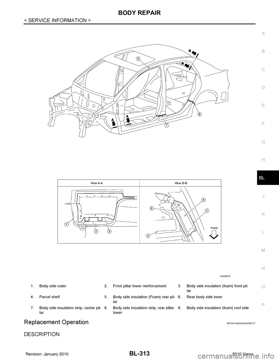
DESCRIPTION
1. Body side outer 2. Front pillar lower reinforcement 3. Body side insulation (foam) front pil-
lar
4. Parcel shelf 5. Body side insulation (Foam) rear pil-
lar 6. Rear body side inner
7. Body side insulation strip, center pil- lar 8. Body side insulation strip, rear pillar
lower 9. Body side insulation (foam) roof side
LIIA2891E
Revision: January 20102010 Versa
Page 1708 of 3745
ON BOARD REFUELING VAPOR RECOVERY (ORVR)EC-443
< COMPONENT DIAGNOSIS > [HR16DE]
C
D
E
F
G H
I
J
K L
M A
EC
NP
O
ON BOARD REFUELING VAPOR RECOVERY (ORVR)
DescriptionINFOID:0000000005398624
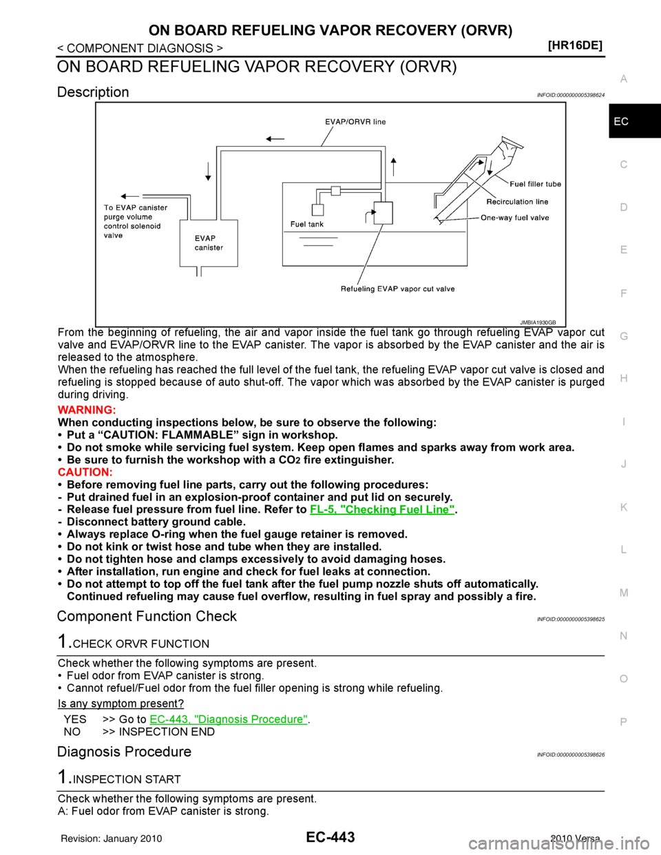
From the beginning of refueling, the air and vapor insi
de the fuel tank go through refueling EVAP vapor cut
valve and EVAP/ORVR line to the EVAP canister. The v apor is absorbed by the EVAP canister and the air is
released to the atmosphere.
When the refueling has reached the full level of the fuel tank, the refueling EVAP vapor cut valve is closed and
refueling is stopped because of auto shut-off. The vapor which was absorbed by the EVAP canister is purged
during driving.
WARNING:
When conducting inspectio ns below, be sure to observe the following:
• Put a “CAUTION: FLAMMABL E” sign in workshop.
• Do not smoke while servicing fuel system. Keep open flames and sparks away from work area.
• Be sure to furnish the workshop with a CO
2 fire extinguisher.
CAUTION:
• Before removing fuel line parts, carry out the following procedures:
- Put drained fuel in an explosion-proof containe r and put lid on securely.
- Release fuel pressure from fuel line. Refer to FL-5, "
Checking Fuel Line".
- Disconnect battery ground cable.
• Always replace O-ring when the fu el gauge retainer is removed.
• Do not kink or twist hose and tube when they are installed.
• Do not tighten hose and clamps excessively to avoid damaging hoses.
• After installation, run engine and check for fuel leaks at connection.
• Do not attempt to top off the fuel tank after the fuel pump nozzle shuts off automatically.
Continued refueling may cause fuel overflow, resulting in fuel spray and possibly a fire.
Component Function CheckINFOID:0000000005398625
1.CHECK ORVR FUNCTION
Check whether the following symptoms are present.
• Fuel odor from EVAP canister is strong.
• Cannot refuel/Fuel odor from the fuel filler opening is strong while refueling.
Is any symptom present?
YES >> Go to EC-443, "Diagnosis Procedure".
NO >> INSPECTION END
Diagnosis ProcedureINFOID:0000000005398626
1.INSPECTION START
Check whether the following symptoms are present.
A: Fuel odor from EVAP canister is strong.
JMBIA1930GB
Revision: January 20102010 Versa