2010 NISSAN LATIO manual transmission
[x] Cancel search: manual transmissionPage 619 of 3745
BL-110
< SERVICE INFORMATION >
INTELLIGENT KEY SYSTEM
*1: With continuously variable transmission (CVT) or automatic transmission (A/T).
*2: With manual transmission (M/T).
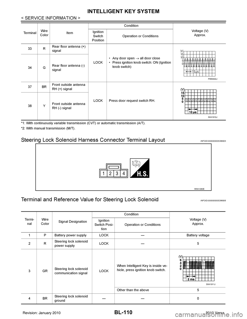
Steering Lock Solenoid Harn ess Connector Terminal LayoutINFOID:0000000005396605
Terminal and Reference Valu e for Steering Lock SolenoidINFOID:0000000005396606
33 RRear floor antenna (+)
signal
LOCK• Any door open
→ all door close
• Press ignition knob switch: ON (Ignition knob switch)
34 G Rear floor antenna (-)
signal
37 BR Front outside antenna
RH (+) signal
LOCK Press door request switch RH.
38 Y Front outside antenna
RH (-) signal
Te r m i n a l
Wire
Color Item Condition
Voltage (V)Approx.
Ignition
Switch
Position Operation or Conditions
PIIB5502J
SIIA1910J
WIIA1283E
Te r m i -
nal Wire
Color Signal Designation Condition
Voltage (V)Approx.
Ignition
Switch Posi- tion Operation or Conditions
1 P Battery power supply LOCK —Battery voltage
2R Steering lock solenoid
power supply LOCK
— 5
3GR Steering lock solenoid
communication signal
LOCKWhen Intelligent Key is inside ve-
hicle, press ignition knob switch.
Other than the above
5
4BR Steering lock solenoid
ground ——
0
SIIA1911J
Revision: January 20102010 Versa
Page 690 of 3745
BACK DOOR LOCKBL-181
< SERVICE INFORMATION >
C
DE
F
G H
J
K L
M A
B
BL
N
O P
*1: With continuously variable transmission (CVT) or automatic transmission (A/T).
*2: With manual transmission (M/T).
CONSULT-III Function (BCM)INFOID:0000000005396655
CONSULT-III can display each diagnostic item using the diagnostic test modes shown following.
CONSULT-III APPLICATION ITEMS
29 V Back door request
switch (hatchback)
—Press back door request switch.
0
Other than above 5
Trunk opener request
switch (sedan) —Press trunk opener request switch.
0
Other than above 5
31 BR Steering lock solenoid
ground ——
0
32 GR Steering lock solenoid
communication signal LOCKWhen Intelligent Key is inside vehicle,
press ignition knob switch.
Other than above
5
33 R Rear floor antenna (+)
signal
LOCK• Any door open
→ all door close
• Press ignition knob switch: ON (Ignition
knob switch)
34 G Rear floor antenna (-)
signal
37 BR Front outside antenna
RH (+) signal
LOCK Press door request switch RH.
38 Y Front outside antenna
RH (-) signal
Terminal
Wire
Color Item Condition
Voltage (V)Approx.
Ignition
Switch
Position Operation or Conditions
SIIA1911J
PIIB5502J
SIIA1910J
Diagnostic mode
Description
WORK SUPPORT Supports inspections and adjustments. Commands are transmitted to the BCM for setting the status
suitable for required operation, input/output signals are received from the BCM and received date
is displayed.
DATA MONITOR Displays BCM input/output data in real time. ACTIVE TEST Operation of electrical loads can be checked by sending drive signal to them.
SELF DIAGNOSTIC RESULT Displays BCM self-diagnosis results.
CAN DIAG SUPPORT MNTR The result of transmit/receive diagnosis of CAN communication can be read. ECU IDENTIFICATION BCM part number can be read.CONFIGURATION Performs BCM configuration read/write functions.
Revision: January 20102010 Versa
Page 714 of 3745
TRUNK LID OPENERBL-205
< SERVICE INFORMATION >
C
DE
F
G H
J
K L
M A
B
BL
N
O P
*1: With continuously variable transmission (CVT) or automatic transmission (A/T).
*2: With manual transmission (M/T).
CONSULT-III Function (BCM)INFOID:0000000005396673
CONSULT-III can display each diagnostic item using the diagnostic test modes shown following.
CONSULT-III APPLICATION ITEMS
29 V Back door request
switch (hatchback)
—Press back door request switch.
0
Other than above 5
Trunk opener request
switch (sedan) —Press trunk opener request switch.
0
Other than above 5
31 BR Steering lock solenoid
ground ——
0
32 GR Steering lock solenoid
communication signal LOCKWhen Intelligent Key is inside vehicle,
press ignition knob switch.
Other than above
5
33 R Rear floor antenna (+)
signal
LOCK• Any door open
→ all door close
• Press ignition knob switch: ON (Ignition
knob switch)
34 G Rear floor antenna (-)
signal
37 BR Front outside antenna
RH (+) signal
LOCK Press door request switch RH.
38 Y Front outside antenna
RH (-) signal
Terminal
Wire
Color Item Condition
Voltage (V)Approx.
Ignition
Switch
Position Operation or Conditions
SIIA1911J
PIIB5502J
SIIA1910J
Diagnostic mode
Description
WORK SUPPORT Supports inspections and adjustments. Commands are transmitted to the BCM for setting the sta-
tus suitable for required operation, input/output signals are received from the BCM and received
date is displayed.
DATA MONITOR Displays BCM input/output data in real time. ACTIVE TEST Operation of electrical loads can be checked by sending drive signal to them.
SELF DIAGNOSTIC RESULT Displays BCM self-diagnosis results.
CAN DIAG SUPPORT MNTR The result of transmit/receive diagnosis of CAN communication can be read. ECU IDENTIFICATION BCM part number can be read.CONFIGURATION Performs BCM configuration read/write functions.
Revision: January 20102010 Versa
Page 742 of 3745
VEHICLE SECURITY (THEFT WARNING) SYSTEMBL-233
< SERVICE INFORMATION >
C
DE
F
G H
J
K L
M A
B
BL
N
O P
*1: With continuously variable transmission (CVT) or automatic transmission (A/T).
*2: With manual transmission (M/T).
CONSULT-III Function (BCM)INFOID:0000000005396689
CONSULT-III can display each diagnostic item using the diagnostic test modes shown following.
CONSULT-III APPLICATION ITEM
29 V Back door request
switch (hatchback)
—Press back door request switch.
0
Other than above 5
Trunk opener request
switch (sedan) —Press trunk opener request switch.
0
Other than above 5
31 BR Steering lock solenoid
ground ——
0
32 GR Steering lock solenoid
communication signal LOCKWhen Intelligent Key is inside vehicle,
press ignition knob switch.
Other than above
5
33 R Rear floor antenna (+)
signal
LOCK• Any door open
→ all door close
• Press ignition knob switch: ON (Ignition
knob switch)
34 G Rear floor antenna (-)
signal
37 BR Front outside antenna
RH (+) signal
LOCK Press door request switch RH.
38 Y Front outside antenna
RH (-) signal
Terminal
Wire
Color Item Condition
Voltage (V)Approx.
Ignition
Switch
Position Operation or Conditions
SIIA1911J
PIIB5502J
SIIA1910J
Diagnostic mode
Description
WORK SUPPORT Supports inspections and adjustments. Commands are transmitted to the BCM for setting the sta-
tus suitable for required operation, input/output signals are received from the BCM and received
date is displayed.
DATA MONITOR Displays BCM input/output data in real time. ACTIVE TEST Operation of electrical loads can be checked by sending drive signal to them.
SELF DIAGNOSTIC RESULT Displays BCM self-diagnosis results.
CAN DIAG SUPPORT MNTR The result of transmit/receive diagnosis of CAN communication can be read. ECU IDENTIFICATION BCM part number can be read.CONFIGURATION Performs BCM configuration read/write functions.
Revision: January 20102010 Versa
Page 2552 of 3745
![NISSAN LATIO 2010 Service Repair Manual ENGINE ASSEMBLYEM-193
< SERVICE INFORMATION > [MR18DE]
C
D
E
F
G H
I
J
K L
M A
EM
NP
O
27. Remove A/C compressor with piping connected from t
he engine. Temporarily secure it on the vehicle side
with NISSAN LATIO 2010 Service Repair Manual ENGINE ASSEMBLYEM-193
< SERVICE INFORMATION > [MR18DE]
C
D
E
F
G H
I
J
K L
M A
EM
NP
O
27. Remove A/C compressor with piping connected from t
he engine. Temporarily secure it on the vehicle side
with](/manual-img/5/57358/w960_57358-2551.png)
ENGINE ASSEMBLYEM-193
< SERVICE INFORMATION > [MR18DE]
C
D
E
F
G H
I
J
K L
M A
EM
NP
O
27. Remove A/C compressor with piping connected from t
he engine. Temporarily secure it on the vehicle side
with a rope to avoid putting load on it. Refer to MTC-81, "
Removal and Installation of Compressor -
MR18DE".
28. Remove the intake manifold to prevent the hanging chain from interfering. Refer to EM-137, "
Compo-
nent".
29. Install engine slinger to cylinder head front left side (A) and rear right side (B) and support the engine position with a hoist.
30. Support engine and transaxle assembly with a hoist and secure the engine in appropriate position.
31. Use a manual lift table caddy (A) or equivalently rigid tool such as a transmission jack. Securely support bottom of the engine
and the transaxle, and simultaneously adjust hoist tension.
CAUTION:
Put a piece of wood or someth ing similar as the supporting
surface, secure a completely stable condition.
32. Remove torque rod (RH) (1), engine insulator (RH) (2) and engine bracket (RH) (3).
33. Remove engine through bolt-securing nut (C).
34. Remove the engine and the transaxle assembly from the vehicle downward by carefully operating sup- porting tools.
CAUTION:
• During the operation, make sure that no part interferes with the vehicle side.
• Before and during this lifting, alw ays check if any harnesses are left connected.
• During the removal operation, alw ays be careful to prevent the vehicle from falling off the lift due
to changes in the center of gravity.
• If necessary, support the vehicle by setting jack or suitable tool at the rear.
• During operation, securely suppor t the engine by placing a piece of wood under the engine oil
pan and transaxle oil pan. Securely sup port the engine slingers with a hoist.
35. Remove starter motor. Refer to SC-9
.
36. Separate the engine and the transaxle and mount the engine on a suitable engine stand. Refer to AT-233
(A/T models), CVT-173, "Removal and Installation" (CVT models) or MT-61, "Removal and Installation"
(M/T models).
INSTALLATION
Note the following, and install in the reverse order of removal.
: Engine front
Slinger bolts : 25.5 N·m (2.6 kg-m, 19 ft-lb)
LBIA0461E
PBIC3223J
4 : Engine insulator (LH)
A : Engine front side
B : Transaxle side
WBIA0784E
Revision: January 20102010 Versa
Page 2670 of 3745
GI-4
< SERVICE INFORMATION >
PRECAUTIONS
• Replace oil seals, gaskets, packings, O-rings, locking washers, cotter pins, self-locking nuts, etc. with new
ones.
• Replace inner and outer races of tapered roller bearings and needle bearings as a set.
• Arrange the disassembled parts in accordance with their assembled locations and sequence.
• Do not touch the terminals of electrical com ponents which use microcomputers (such as ECM).
Static electricity may damage internal electronic components.
• After disconnecting vacuum or air hoses, atta ch a tag to indicate the proper connection.
• Use only the fluids and lubricants specified in this manual.
• Use approved bonding agent, sealants or their equivalents when required.
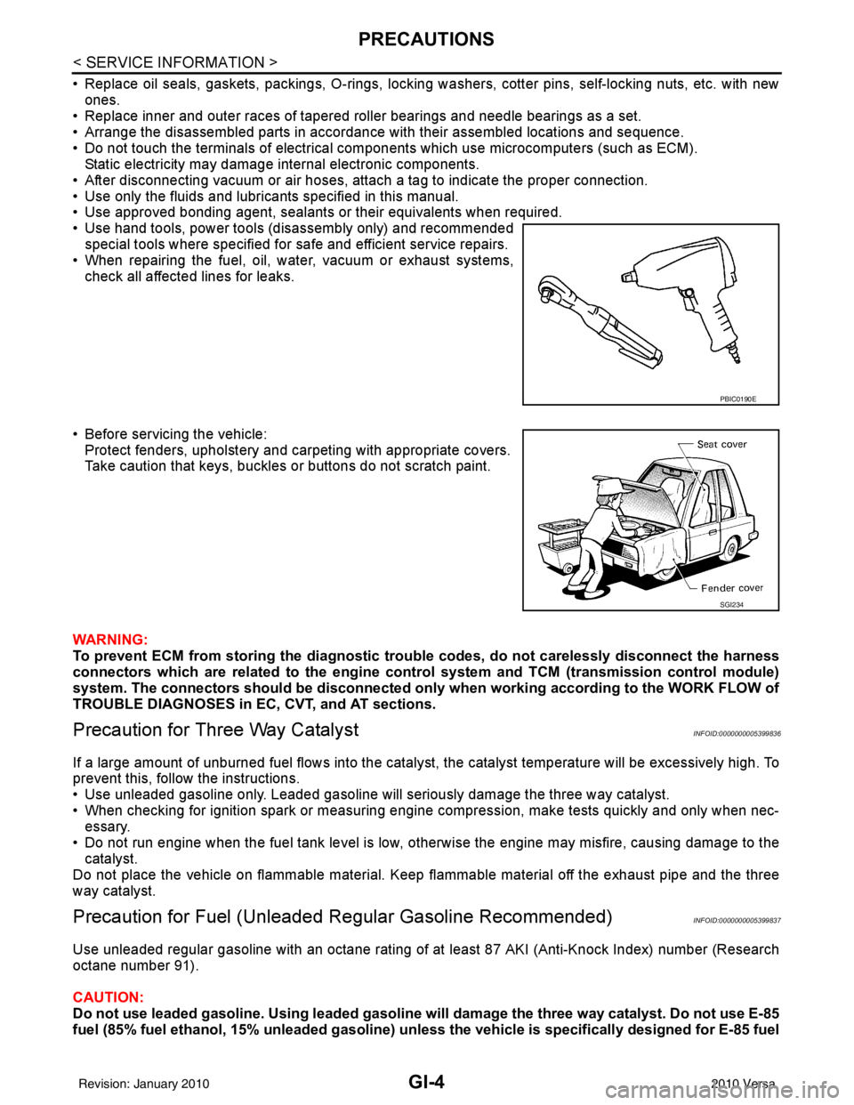
• Use hand tools, power tools (disassembly only) and recommended special tools where specified for safe and efficient service repairs.
• When repairing the fuel, oil, water, vacuum or exhaust systems, check all affected lines for leaks.
• Before servicing the vehicle: Protect fenders, upholstery and carpeting with appropriate covers.
Take caution that keys, buckles or buttons do not scratch paint.
WARNING:
To prevent ECM from storing the diagnostic tro uble codes, do not carelessly disconnect the harness
connectors which are related to the engine control system and TCM (transmission control module)
system. The connectors should be disconnected only when working according to the WORK FLOW of
TROUBLE DIAGNOSES in EC, CVT, and AT sections.
Precaution for Three Way CatalystINFOID:0000000005399836
If a large amount of unburned fuel flows into the catalyst , the catalyst temperature will be excessively high. To
prevent this, follow the instructions.
• Use unleaded gasoline only. Leaded gasoline will seriously damage the three way catalyst.
• When checking for ignition spark or measuring engine compression, make tests quickly and only when nec- essary.
• Do not run engine when the fuel tank level is low, otherwise the engine may misfire, causing damage to the
catalyst.
Do not place the vehicle on flammable material. Keep flammable material off the exhaust pipe and the three
way catalyst.
Precaution for Fuel (Unleade d Regular Gasoline Recommended)INFOID:0000000005399837
Use unleaded regular gasoline with an octane rating of at least 87 AKI (Anti-Knock Index) number (Research
octane number 91).
CAUTION:
Do not use leaded gasoline. Using leaded gasoline will damage the three way catalyst. Do not use E-85
fuel (85% fuel ethanol, 15% unleaded gasoline) unless the vehicle is specifically designed for E-85 fuel
PBIC0190E
SGI234
Revision: January 20102010 Versa
Page 2673 of 3745
HOW TO USE THIS MANUALGI-7
< SERVICE INFORMATION >
C
DE
F
G H
I
J
K L
M B
GI
N
O PHOW TO USE THIS MANUAL
DescriptionINFOID:0000000005399842
This volume explains “Removal, Disassembly, Inst allation, Inspection and Adjustment” and “Trouble Diag-
noses”.
Te r m sINFOID:0000000005399843
• The captions WARNING and CAUTION warn you of steps that must be followed to prevent personal injury
and/or damage to some part of the vehicle.
WARNING indicates the possibility of personal injury if instructions are not followed.
CAUTION indicates the possibility of component damage if instructions are not followed.
BOLD TYPED STATEMENTS except WARNING and CAUTION give you helpful information.
Standard value:Tolerance at inspection and adjustment.
Limit value:The maximum or minimum limit value t hat should not be exceeded at inspection and adjustment.
UnitsINFOID:0000000005399844
• The UNITS given in this manual are primarily expressed as the SI UNIT (International System of Unit), and
alternatively expressed in the metric system and in the yard/pound system.
Also with regard to tightening torque of bolts and nuts, there are descriptions both about range and about the
standard tightening torque.
“Example”
Range
Standard
ContentsINFOID:0000000005399845
• A QUICK REFERENCE INDEX , a black tab (e.g. ) is provided on the first page. You can quickly find the
first page of each section by matching it to the section's black tab.
• THE CONTENTS are listed on the first page of each section.
• THE TITLE is indicated on the upper portion of each page and shows the part or system.
• THE PAGE NUMBER of each section consists of two or three letters which designate the particular section
and a number (e.g. “BR-5”).
• THE SMALL ILLUSTRATIONS show the important steps such as ins pection, use of special tools, knacks of
work and hidden or tricky steps which are not shown in the previous large illustrations.
Assembly, inspection and adjustment procedures for the complicated units such as the automatic transaxle
or transmission, etc. are presented in a step-by-step format where necessary. Outer Socket Lock Nut : 59 - 78 N·m (6.0 - 8.0 kg-m, 43 - 58 ft-lb)
Drive Shaft Installation Bolt : 44.3 N·m (4.5 kg-m, 33 ft-lb)
Revision: January 20102010 Versa
Page 2686 of 3745
GI-20
< SERVICE INFORMATION >
HOW TO USE THIS MANUAL
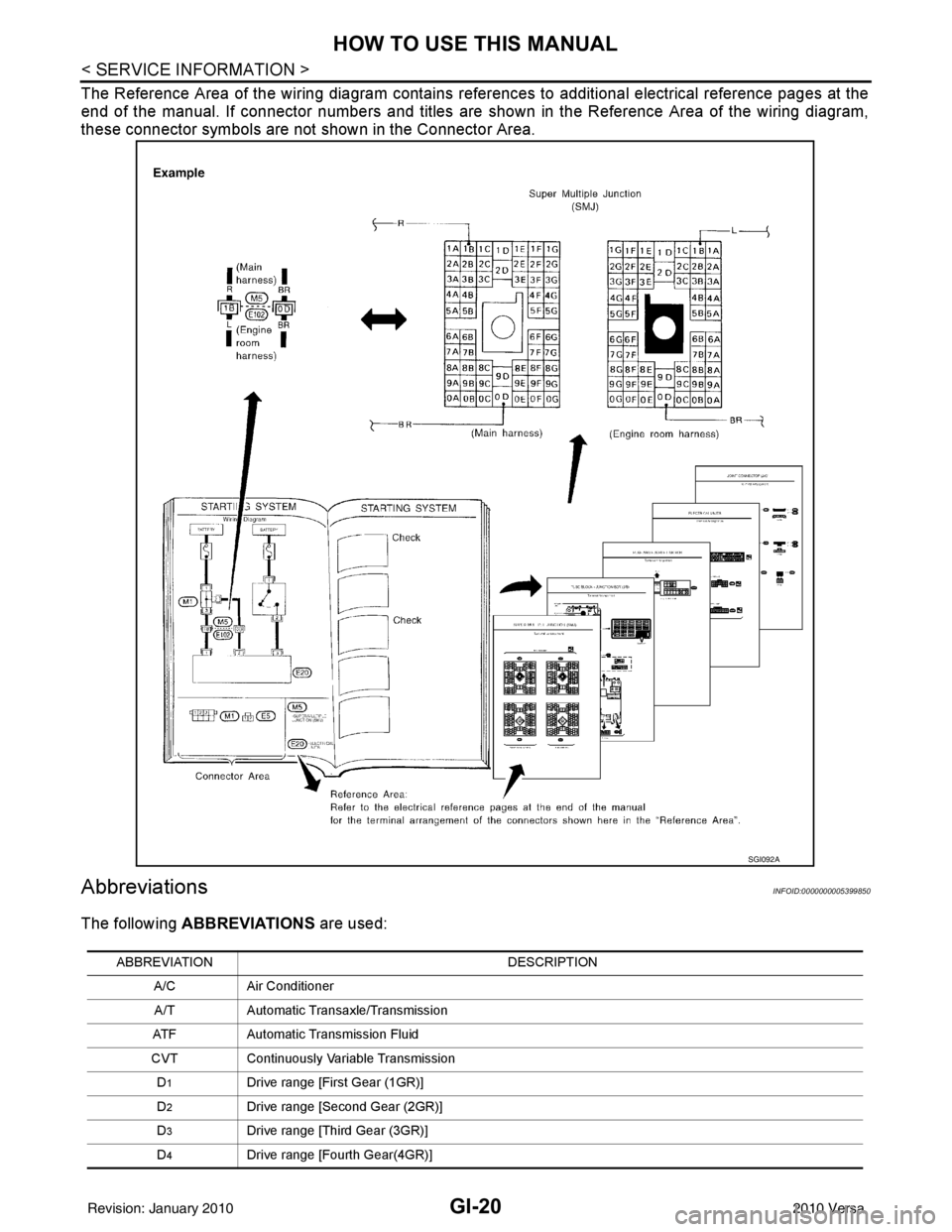
The Reference Area of the wiring diagram contains references to additional electrical reference pages at the
end of the manual. If connector numbers and titles are shown in the Reference Area of the wiring diagram,
these connector symbols are not shown in the Connector Area.
AbbreviationsINFOID:0000000005399850
The following ABBREVIATIONS are used:
SGI092A
ABBREVIATION DESCRIPTION
A/C Air Conditioner
A/T Automatic Transaxle/Transmission
ATF Automatic Transmission Fluid
CVT Continuously Variable Transmission
D
1Drive range [First Gear (1GR)]
D
2Drive range [Second Gear (2GR)]
D
3Drive range [Third Gear (3GR)]
D
4Drive range [Fourth Gear(4GR)]
Revision: January 20102010 Versa