2010 NISSAN LATIO height
[x] Cancel search: heightPage 1469 of 3745
EC-204
< COMPONENT DIAGNOSIS >[HR16DE]
P0137 HO2S2
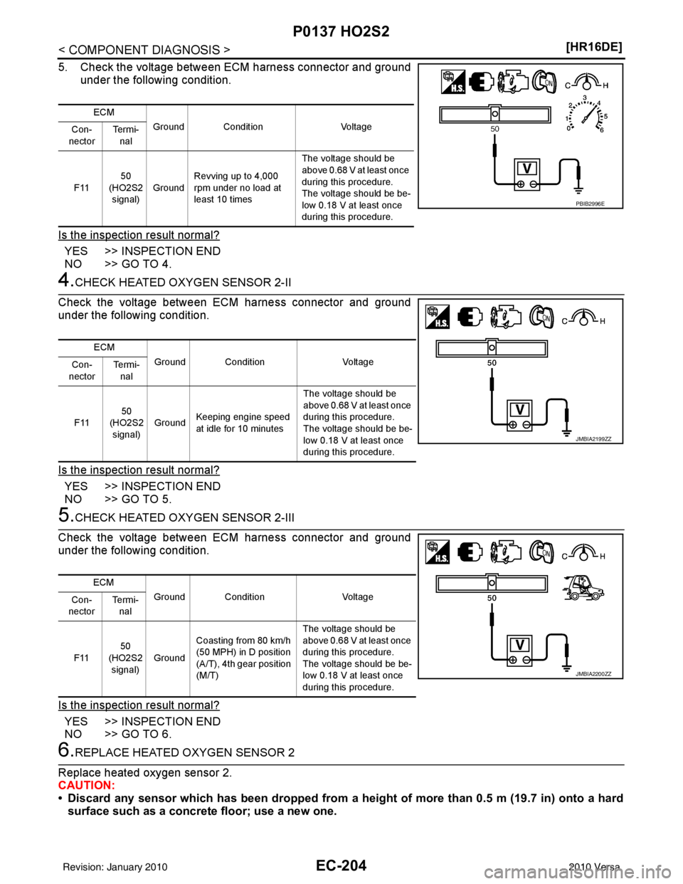
5. Check the voltage between ECM harness connector and ground
under the following condition.
Is the inspection result normal?
YES >> INSPECTION END
NO >> GO TO 4.
4.CHECK HEATED OXYGEN SENSOR 2-II
Check the voltage between ECM harness connector and ground
under the following condition.
Is the inspection result normal?
YES >> INSPECTION END
NO >> GO TO 5.
5.CHECK HEATED OXYGEN SENSOR 2-III
Check the voltage between ECM harness connector and ground
under the following condition.
Is the inspection result normal?
YES >> INSPECTION END
NO >> GO TO 6.
6.REPLACE HEATED OXYGEN SENSOR 2
Replace heated oxygen sensor 2.
CAUTION:
• Discard any sensor which has been dropped from a height of more than 0.5 m (19.7 in) onto a hard surface such as a concrete floor; use a new one.
ECM
Ground Condition Voltage
Con-
nector Te r m i -
nal
F11 50
(HO2S2 signal) Ground Revving up to 4,000
rpm under no load at
least 10 times The voltage should be
above 0.68 V at least once
during this procedure.
The voltage should be be-
low 0.18 V at least once
during this procedure.
PBIB2996E
ECM
Ground Condition Voltage
Con-
nector Te r m i -
nal
F11 50
(HO2S2 signal) Ground
Keeping engine speed
at idle for 10 minutes The voltage should be
above 0.68 V at least once
during this procedure.
The voltage should be be-
low 0.18 V at least once
during this procedure.
JMBIA2199ZZ
ECM
Ground Condition Voltage
Con-
nector Te r m i -
nal
F11 50
(HO2S2 signal) Ground Coasting from 80 km/h
(50 MPH) in D position
(A/T), 4th gear position
(M/T) The voltage should be
above 0.68 V at least once
during this procedure.
The voltage should be be-
low 0.18 V at least once
during this procedure.
JMBIA2200ZZ
Revision: January 20102010 Versa
Page 1477 of 3745
EC-212
< COMPONENT DIAGNOSIS >[HR16DE]
P0138 HO2S2
2. Check the continuity between HO2S2 harne
ss connector or ECM harness connector and ground.
3. Also check harness for short to power.
Is the inspection result normal?
YES >> GO TO 13.
NO >> Repair open circuit or short to ground or short to power in harness or connectors.
13.CHECK HEATED OXYGEN SENSOR 2
Refer to EC-212, "
Component Inspection".
Is the inspection result normal?
YES >> GO TO 15.
NO >> GO TO 14.
14.REPLACE HEATED OXYGEN SENSOR 2
Replace heated oxygen sensor 2.
CAUTION:
• Discard any sensor which has been dropped from a height of more than 0.5 m (19.7 in) onto a hard surface such as a concrete floor; use a new one.
• Before installing new sensor, clean exhaust system threads usi ng Oxygen Sensor Thread Cleaner
[commercial service tool (J-43897-18 or J43897-12)] and approved Anti-seize Lubricant (commercial
service tool).
>> INSPECTION END
15.CHECK INTERMITTENT INCIDENT
Refer to EC-114, "
Diagnosis Procedure".
>> INSPECTION END
Component InspectionINFOID:0000000005398388
1.INSPECTION START
Do you have CONSULT-III?
Do you have CONSULT-III?
YES >> GO TO 2.
NO >> GO TO 3.
2.CHECK HEATED OXYGEN SENSOR 2
With CONSULT-III
1. Turn ignition switch ON and select “DATA MONITOR” mode with CONSULT-III.
2. Start engine and warm it up to normal operating temperature.
3. Turn ignition switch OFF and wait at least 10 seconds.
4. Start engine and keep the engine speed between 3,500 and 4,000 rpm for at least 1 minute under no load.
HO2S2ECM
Continuity
Connector Terminal Connector Terminal
F13 4 F11 50 Existed
HO2S2 Ground Continuity
Connector Terminal
F13 4 Ground Not existed
ECM Ground Continuity
Connector Terminal
F11 50 Ground Not existed
Revision: January 20102010 Versa
Page 1479 of 3745
EC-214
< COMPONENT DIAGNOSIS >[HR16DE]
P0138 HO2S2
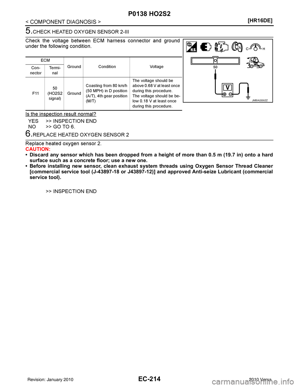
5.CHECK HEATED OXYGEN SENSOR 2-III
Check the voltage between ECM harness connector and ground
under the following condition.
Is the inspection result normal?
YES >> INSPECTION END
NO >> GO TO 6.
6.REPLACE HEATED OXYGEN SENSOR 2
Replace heated oxygen sensor 2.
CAUTION:
• Discard any sensor which has been dropped from a height of more than 0.5 m (19.7 in) onto a hard surface such as a concrete floor; use a new one.
• Before installing new sensor, clean exhaust system threads usi ng Oxygen Sensor Thread Cleaner
[commercial service tool (J-43897-18 or J43897-12)] and approved Anti-seize Lubricant (commercial
service tool).
>> INSPECTION END
ECM Ground Condition Voltage
Con-
nector Te r m i -
nal
F11 50
(HO2S2
signal) Ground Coasting from 80 km/h
(50 MPH) in D position
(A/T), 4th gear position
(M/T) The voltage should be
above 0.68 V at least once
during this procedure.
The voltage should be be-
low 0.18 V at least once
during this procedure.
JMBIA2200ZZ
Revision: January 20102010 Versa
Page 1485 of 3745
EC-220
< COMPONENT DIAGNOSIS >[HR16DE]
P0139 HO2S2
6.REPLACE HEATED OXYGEN SENSOR 2
Replace heated oxygen sensor 2.
CAUTION:
• Discard any sensor which has been dropped from a height of more than 0.5 m (19.7 in) onto a hard surface such as a concrete floor; use a new one.
• Before installing new sensor, clean exhaust system threads usi ng Oxygen Sensor Thread Cleaner
[commercial service tool (J-43897-18 or J43897-12)] and approved Anti-seize Lubricant (commercial
service tool).
>> INSPECTION END
7.CHECK INTERMITTENT INCIDENT
Refer to EC-114, "
Diagnosis Procedure".
>> INSPECTION END
Component InspectionINFOID:0000000005398394
1.INSPECTION START
Do you have CONSULT-III?
Do you have CONSULT-III?
YES >> GO TO 2.
NO >> GO TO 3.
2.CHECK HEATED OXYGEN SENSOR 2
With CONSULT-III
1. Turn ignition switch ON and select “DATA MONITOR” mode with CONSULT-III.
2. Start engine and warm it up to normal operating temperature.
3. Turn ignition switch OFF and wait at least 10 seconds.
4. Start engine and keep the engine speed between 3,500 and 4,000 rpm for at least 1 minute under no load.
5. Let engine idle for 1 minute.
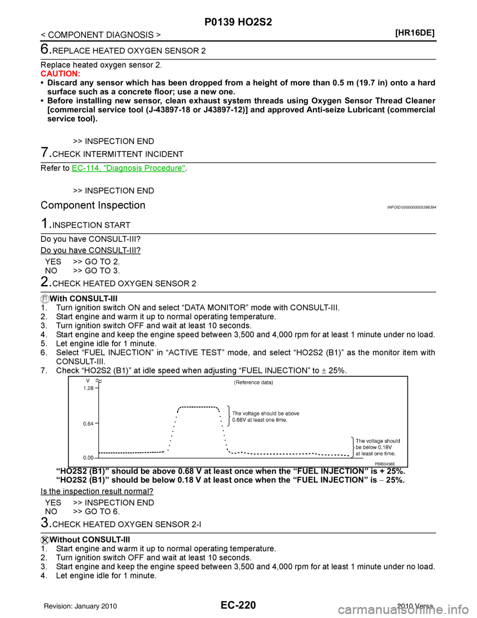
6. Select “FUEL INJECTION” in “ACT IVE TEST” mode, and select “HO2S2 (B1)” as the monitor item with
CONSULT-III.
7. Check “HO2S2 (B1)” at idle speed when adjusting “FUEL INJECTION” to ± 25%.
“HO2S2 (B1)” should be above 0.68 V at l east once when the “FUEL INJECTION” is + 25%.
“HO2S2 (B1)” should be below 0.18 V at least once when the “FUEL INJECTION” is − 25%.
Is the inspection result normal?
YES >> INSPECTION END
NO >> GO TO 6.
3.CHECK HEATED OXYGEN SENSOR 2-I
Without CONSULT-III
1. Start engine and warm it up to normal operating temperature.
2. Turn ignition switch OFF and wait at least 10 seconds.
3. Start engine and keep the engine speed between 3,500 and 4,000 rpm for at least 1 minute under no load.
4. Let engine idle for 1 minute.
PBIB3458E
Revision: January 20102010 Versa
Page 1918 of 3745
DTC P0031, P0032 A/F SENSOR 1 HEATEREC-653
< SERVICE INFORMATION > [MR18DE]
C
D
E
F
G H
I
J
K L
M A
EC
NP
O
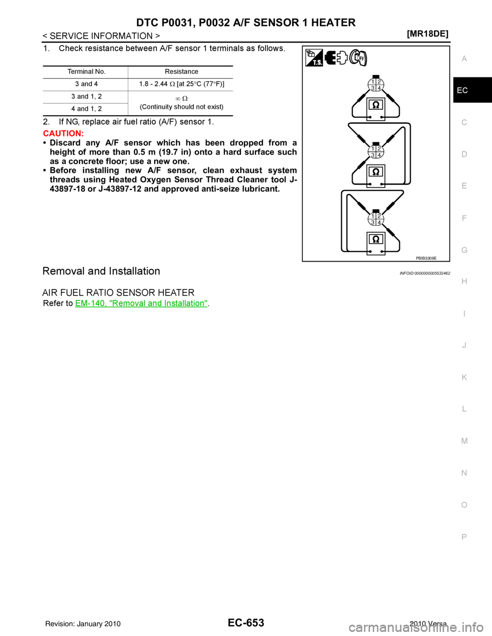
1. Check resistance between A/F sensor 1 terminals as follows.
2. If NG, replace air fuel ratio (A/F) sensor 1.
CAUTION:
• Discard any A/F sensor which has been dropped from a
height of more than 0.5 m ( 19.7 in) onto a hard surface such
as a concrete floor; use a new one.
• Before installing new A/F sensor, clean exhaust system
threads using Heated Oxygen Sensor Thread Cleaner tool J-
43897-18 or J-43897-12 and approved anti-seize lubricant.
Removal and InstallationINFOID:0000000005532462
AIR FUEL RATIO SENSOR HEATER
Refer to EM-140, "Removal and Installation".
Terminal No. Resistance
3 and 4 1.8 - 2.44 Ω [at 25 °C (77 °F)]
3 and 1, 2 ∞ Ω
(Continuity should not exist)
4 and 1, 2
PBIB3309E
Revision: January 20102010 Versa
Page 1923 of 3745
EC-658
< SERVICE INFORMATION >[MR18DE]
DTC P0037, P0038 HO2S2 HEATER
Component Inspection
INFOID:0000000005532469
HEATED OXYGEN SENSOR 2 HEATER
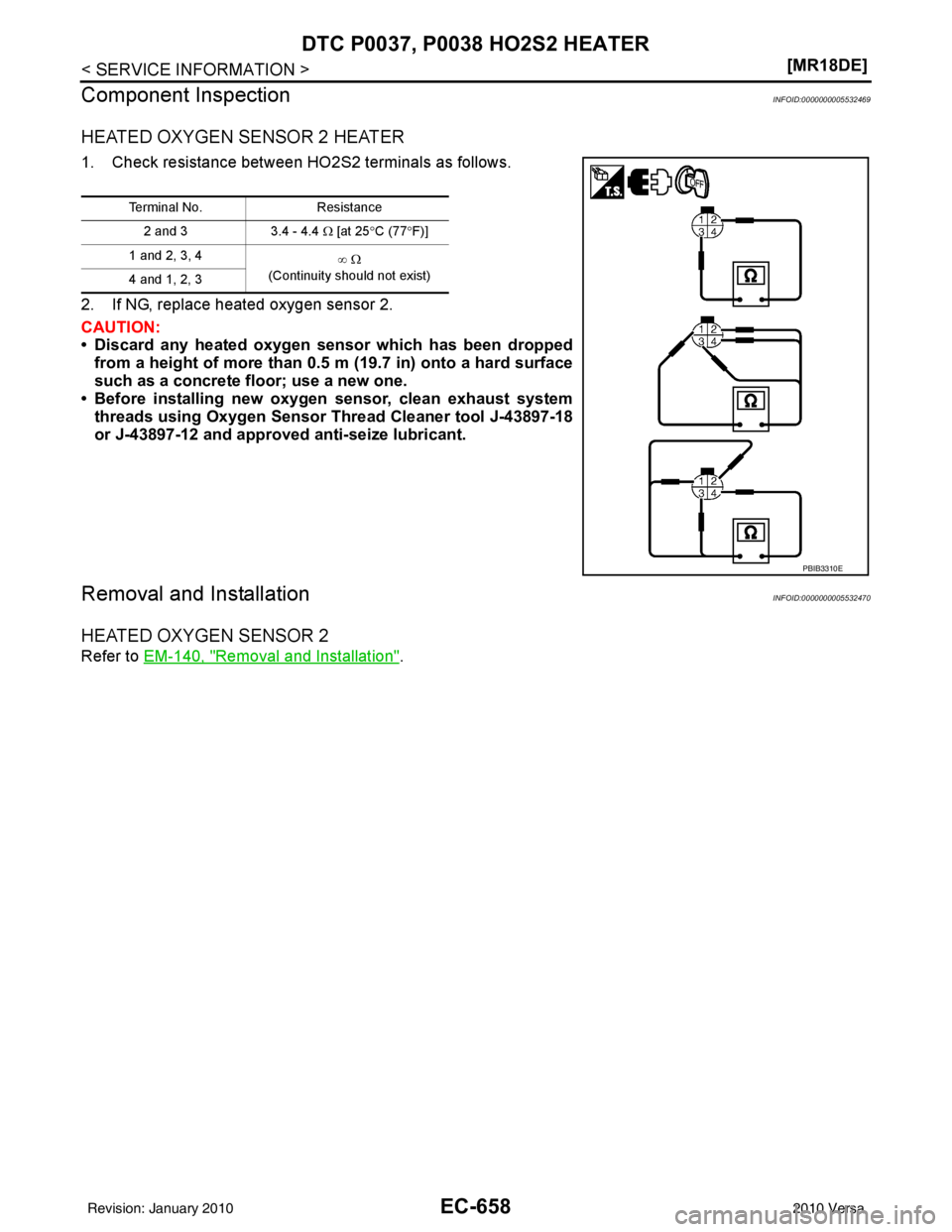
1. Check resistance between HO2S2 terminals as follows.
2. If NG, replace heated oxygen sensor 2.
CAUTION:
• Discard any heated oxygen sensor which has been dropped from a height of more than 0.5 m (19.7 in) onto a hard surface
such as a concrete floor; use a new one.
• Before installing new oxygen sensor, clean exhaust system threads using Oxygen Sensor Thread Cleaner tool J-43897-18
or J-43897-12 and approved anti-seize lubricant.
Removal and InstallationINFOID:0000000005532470
HEATED OXYGEN SENSOR 2
Refer to EM-140, "Removal and Installation".
Terminal No. Resistance
2 and 3 3.4 - 4.4 Ω [at 25°C (77 °F)]
1 and 2, 3, 4 ∞ Ω
(Continuity should not exist)
4 and 1, 2, 3
PBIB3310E
Revision: January 20102010 Versa
Page 1973 of 3745
EC-708
< SERVICE INFORMATION >[MR18DE]
DTC P0130 A/F SENSOR 1
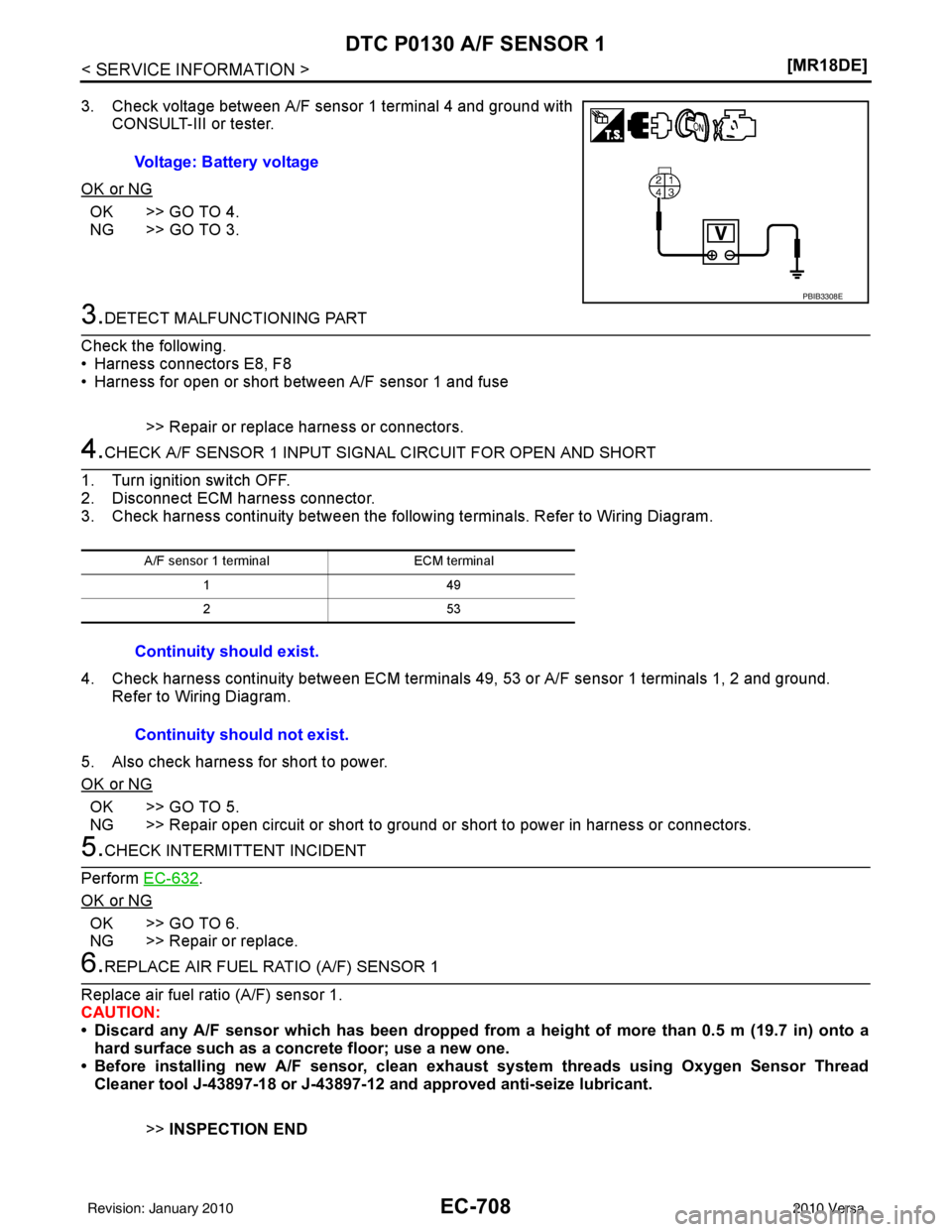
3. Check voltage between A/F sensor 1 terminal 4 and ground with
CONSULT-III or tester.
OK or NG
OK >> GO TO 4.
NG >> GO TO 3.
3.DETECT MALFUNCTIONING PART
Check the following.
• Harness connectors E8, F8
• Harness for open or short between A/F sensor 1 and fuse
>> Repair or replace harness or connectors.
4.CHECK A/F SENSOR 1 INPUT SIGN AL CIRCUIT FOR OPEN AND SHORT
1. Turn ignition switch OFF.
2. Disconnect ECM harness connector.
3. Check harness continuity between the following terminals. Refer to Wiring Diagram.
4. Check harness continuity between ECM terminals 49, 53 or A/F sensor 1 terminals 1, 2 and ground. Refer to Wiring Diagram.
5. Also check harness for short to power.
OK or NG
OK >> GO TO 5.
NG >> Repair open circuit or short to ground or short to power in harness or connectors.
5.CHECK INTERMITTENT INCIDENT
Perform EC-632
.
OK or NG
OK >> GO TO 6.
NG >> Repair or replace.
6.REPLACE AIR FUEL RATIO (A/F) SENSOR 1
Replace air fuel ratio (A/F) sensor 1.
CAUTION:
• Discard any A/F sensor which has b een dropped from a height of more than 0.5 m (19.7 in) onto a
hard surface such as a concrete floor; use a new one.
• Before installing new A/F sensor, clean exhaust system threads using Oxygen Sensor Thread Cleaner tool J-43897-18 or J-43897-12 and approved anti-seize lubricant.
>>INSPECTION END
Voltage: Battery voltage
PBIB3308E
A/F sensor 1 terminal
ECM terminal
14 9
25 3
Continuity should exist.
Continuity should not exist.
Revision: January 20102010 Versa
Page 1979 of 3745
EC-714
< SERVICE INFORMATION >[MR18DE]
DTC P0131 A/F SENSOR 1
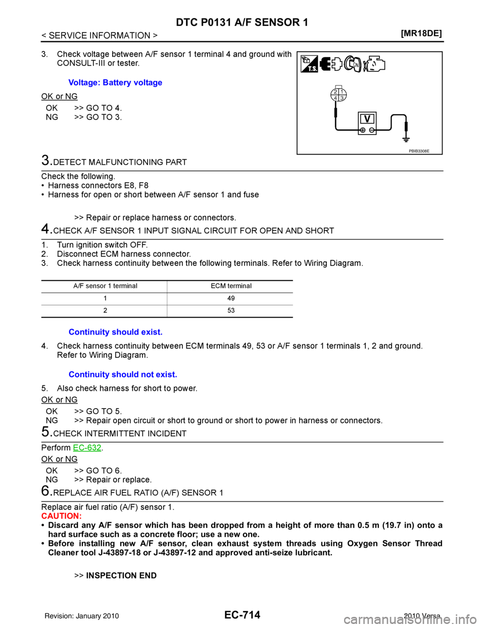
3. Check voltage between A/F sensor 1 terminal 4 and ground with
CONSULT-III or tester.
OK or NG
OK >> GO TO 4.
NG >> GO TO 3.
3.DETECT MALFUNCTIONING PART
Check the following.
• Harness connectors E8, F8
• Harness for open or short between A/F sensor 1 and fuse
>> Repair or replace harness or connectors.
4.CHECK A/F SENSOR 1 INPUT SIGN AL CIRCUIT FOR OPEN AND SHORT
1. Turn ignition switch OFF.
2. Disconnect ECM harness connector.
3. Check harness continuity between the following terminals. Refer to Wiring Diagram.
4. Check harness continuity between ECM terminals 49, 53 or A/F sensor 1 terminals 1, 2 and ground. Refer to Wiring Diagram.
5. Also check harness for short to power.
OK or NG
OK >> GO TO 5.
NG >> Repair open circuit or short to ground or short to power in harness or connectors.
5.CHECK INTERMITTENT INCIDENT
Perform EC-632
.
OK or NG
OK >> GO TO 6.
NG >> Repair or replace.
6.REPLACE AIR FUEL RATIO (A/F) SENSOR 1
Replace air fuel ratio (A/F) sensor 1.
CAUTION:
• Discard any A/F sensor which has b een dropped from a height of more than 0.5 m (19.7 in) onto a
hard surface such as a concrete floor; use a new one.
• Before installing new A/F sensor, clean exhaust system threads using Oxygen Sensor Thread Cleaner tool J-43897-18 or J-43897-12 and approved anti-seize lubricant.
>>INSPECTION END
Voltage: Battery voltage
PBIB3308E
A/F sensor 1 terminal
ECM terminal
14 9
25 3
Continuity should exist.
Continuity should not exist.
Revision: January 20102010 Versa