2010 NISSAN LATIO TRansmission
[x] Cancel search: TRansmissionPage 41 of 3745

AT-24
< SERVICE INFORMATION >
A/T CONTROL SYSTEM
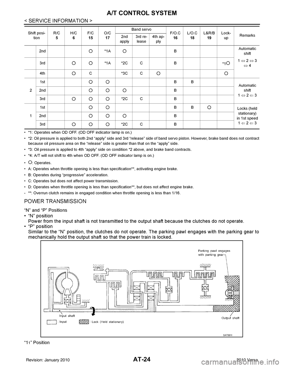
• *1: Operates when OD OFF. (OD OFF indicator lamp is on.)
• *2: Oil pressure is applied to both 2nd “apply” side and 3rd “release” side of band servo piston. However, brake band does not contract
because oil pressure area on the “release” side is greater than that on the “apply” side.
• *3: Oil pressure is applied to 4th “apply” side on condition *2 above, and brake band contracts.
• *4: A/T will not shift to 4th when OD OFF. (OD OFF indicator lamp is on.)
• : Operates.
• A: Operates when throttle opening is less than specification**, activating engine brake.
• B: Operates during “pro gressive” acceleration.
• C: Operates but does not affect power transmission.
• D: Operates when throttle opening is less than specification**, but does not affect engine brake.
- **: Overrun clutch remains in engaged condition when throttle opening is less than 1/16.
POWER TRANSMISSION
“N” and “P” Positions
• “N” position Power from the input shaft is not transmitted to the output shaft because the clutches do not operate.
• “P” position
Similar to the “N” position, the clutches do not operate. The parking pawl engages with the parking gear to
mechanically hold the output shaft so that the power train is locked.
“11” Position
2nd *1A BAutomatic
shift
3rd *1A *2C C B
*11
⇔ 2 ⇔ 3
⇔ 4
4th C*3C C
2 1st
BB
Automatic
shift
1 ⇔ 2 ⇐ 3
2nd
B
3rd *2C CB
1 1st
BB
Locks (held
stationary)
in 1st speed 1 ⇐ 2 ⇐ 3
2nd
B
3rd *2C CB
Shift posi-
tion R/C
5 H/C
6 F/C
15 O/C
17 Band servo
F/O.C
16 L/O.C
18 L&R/B
19 Lock-
up Remarks
2nd
apply 3rd re-
lease 4th ap-
ply
SAT991I
Revision: January 20102010 Versa
Page 45 of 3745

AT-28
< SERVICE INFORMATION >
A/T CONTROL SYSTEM
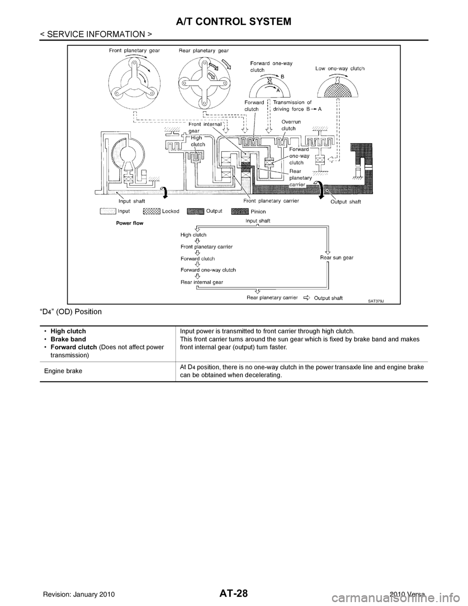
“D4” (OD) Position
SAT379J
•High clutch
• Brake band
• Forward clutch (Does not affect power
transmission) Input power is transmitted to front carrier through high clutch.
This front carrier turns around the sun gear which is fixed by brake band and makes
front internal gear (output) turn faster.
Engine brake At D
4 position, there is no one-way clutch in the power transaxle line and engine brake
can be obtained when decelerating.
Revision: January 20102010 Versa
Page 47 of 3745

AT-30
< SERVICE INFORMATION >
A/T CONTROL SYSTEM
TCM Function
INFOID:0000000005397221
The function of the TCM is to:
• Receive input signals sent from various switches and sensors.
• Determine required line pressure, shifting poi nt, lock-up operation, and engine brake operation.
• Send required output signals to the respective solenoids.
CONTROL SYSTEM OUTLINE
The automatic transaxle senses vehicle operating conditions through various sensors or signals. It always
controls the optimum shift position and reduces shifting and lock-up shocks.
SAT381J
SWITCHES & SENSORS
⇒TCM
⇒ACTUATORS
Transmission range switch
Accelerator pedal position signal
Closed throttle position signal
Wide open throttle position signal
Engine speed signal
A/T fluid temperature sensor
Output speed sensor
Input speed sensor
Vehicle speed signal
Overdrive control switch signal
Stop lamp switch signal Shift control
Line pressure control
Lock-up control
Overrun clutch control
Fail-safe control
Self-diagnosis
CONSULT-III communication
line control
Shift solenoid valve A
Shift solenoid valve B
Overrun clutch solenoid valve
Torque converter clutch solenoid
valve
Line pressure solenoid valve
OD OFF indicator lamp
Revision: January 20102010 Versa
Page 48 of 3745

A/T CONTROL SYSTEMAT-31
< SERVICE INFORMATION >
DE
F
G H
I
J
K L
M A
B
AT
N
O P
CONTROL SYSTEM DIAGRAM
CAN CommunicationINFOID:0000000005397222
SYSTEM DESCRIPTION
CAN (Controller Area Network) is a serial communication line for real time application. It is an on-vehicle mul-
tiplex communication line with high data communication speed and excellent error detection ability. Many elec-
tronic control units are equipped onto a vehicle, and each control unit shares information and links with other
control units during operation (not independent). In CAN communication, control units are connected with 2
communication lines (CAN H line, CAN L line) allowing a high rate of information transmission with less wiring.
Each control unit transmits/receives data but selectively reads required data only. For details, refer to LAN-7,
"System Description".
Input/Output Signal of TCMINFOID:0000000005397223
JSDIA1518GB
Control itemLine
pressure control Veh icl e
speed
control Shift
control Lock-up
control Engine
brake
control Fail-safe
function Self-diag-
nostics
function
Input Accelerator pedal position signal
(*5)XXXXX(*3) XX
Output speed sensor X X X X X (*3) X X
Vehicle speed signal (*1) X (*1) X (*1) X (*1) X X
Closed throttle position signal
(*5)(*2) X (*2) X X X(*4) X
Wide open throttle position signal
(*5)(*2) X (*2) X (*4) X
Input speed sensor X XXX X
Engine speed signal XXX X
Transmission range sw itch XXXXX(*3) X(*4) X
Stop lamp switch signal
(*5)XX ( *4 ) X
A/T fluid temperature sensors
(*5)XXXX XX
Overdrive control switch signal
(*5)XXXX (*4) X
TCM power supply voltage signal X XX X
Revision: January 20102010 Versa
Page 51 of 3745

AT-34
< SERVICE INFORMATION >
A/T CONTROL SYSTEM
CONTROL OF SHIFT VALVES A AND B
Pilot pressure generated by the operation of shift solenoid valves A and B is applied to the end face of shift
valves A and B.
The figure above shows the operation of shift valve B. When the shift solenoid valve is “ON”, pilot pressure
applied to the end face of the shift valve overcomes spring force, moving the valve upward.
Lock-up ControlINFOID:0000000005397226
The torque converter clutch piston in the torque conver ter is locked to eliminate torque converter slip and to
increase power transmission efficiency. The solenoid va lve is controlled by an ON-OFF duty signal sent from
the TCM. The signal is converted to an oil pressure si gnal which controls the torque converter clutch piston.
CONDITIONS FOR LOCK-UP OPERATION
When vehicle is driven in 3GR and 4GR positions, v ehicle speed and throttle opening are detected. If the
detected values fall within the lock-up zone me morized in the TCM, lock-up is performed.
TORQUE CONVERTER CLUTCH SOLENOID VALVE CONTROL
Gear position123 4
Shift solenoid valve A ON (Closed)OFF (Open)OFF (Open) ON (Closed)
Shift solenoid valve B ON (Closed)ON (Closed) OFF (Open) OFF (Open)
SAT009J
OD ONOFF
Selector lever “D” position
Gear position D
4D3
Vehicle speed signal More than set value
Accelerator pedal position signal Less than set opening
Closed throttle position signal OFF
A/T fluid temperature sensor More than 40°C (104 °F)
Revision: January 20102010 Versa
Page 56 of 3745

ON BOARD DIAGNOSTIC (OBD) SYSTEMAT-39
< SERVICE INFORMATION >
DE
F
G H
I
J
K L
M A
B
AT
N
O P
ON BOARD DIAGNOSTIC (OBD) SYSTEM
IntroductionINFOID:0000000005397230
A/T system has two self-diagnostic systems.
The first is emission-related on board diagnostic system (OBD-II) performed by the TCM in combination with
the ECM. The malfunction is indicated by the MIL (malf unction indicator lamp) and is stored as a DTC in the
ECM memory but not the TCM memory.
The second is the TCM original self-diagnosis indicated by the OD OFF indicator lamp. The malfunction is
stored in the TCM memory. The detected items are ov erlapped with OBD-II self-diagnostic items. For detail,
refer to AT-77, "
CONSULT-III Function (TRANSMISSION)" .
OBD-II Function for A/T SystemINFOID:0000000005397231
The ECM provides emission-related on board diagnostic (O BD-II) functions for the A/T system. One function
is to receive a signal from the TCM used with OBD-rela ted parts of the A/T system. The signal is sent to the
ECM when a malfunction occurs in the corresponding OBD-re lated part. The other function is to indicate a
diagnostic result by means of the MIL (malfunction indica tor lamp) on the instrument panel. Sensors, switches
and solenoid valves are used as sensing elements.
The MIL automatically illuminates in One or Two Trip Detection Logic when a malfunction is sensed in relation
to A/T system parts.
One or Two Trip Detection Logic of OBD-IIINFOID:0000000005397232
ONE TRIP DETECTION LOGIC
If a malfunction is sensed during the first test drive, the MIL will illuminate and the malfunction will be stored in
the ECM memory as a DTC. The TCM is not provided with such a memory function.
TWO TRIP DETECTION LOGIC
When a malfunction is sensed during the first test drive, it is stored in the ECM memory as a 1st trip DTC
(diagnostic trouble code) or 1st trip freeze frame data. At this point, the MIL will not illuminate. — 1st trip
If the same malfunction as that experienced during the fi rst test drive is sensed during the second test drive,
the MIL will illuminate. — 2nd trip
The “trip” in the “One or Two Trip Detection Logic” m eans a driving mode in which self-diagnosis is performed
during vehicle operation.
OBD-II Diagnostic Trouble Code (DTC)INFOID:0000000005397233
HOW TO READ DTC AND 1ST TRIP DTC
DTC and 1st trip DTC can be read by the following methods.
( with CONSULT-III or GST) CONSULT-III or GST (Generic Scan Tool) Examples: P0705, P0720 etc.
These DTC are prescribed by SAE J2012.
(CONSULT-III also displays the malfunctioning component or system.)
• 1st trip DTC No. is the same as DTC No.
• Output of the diagnostic trouble code indicates that the indicated circuit has a malfunction. How-
ever, in case of the Mode II and GST, they do not indicate whether the malfunction is still occurring or
occurred in the past and returned to normal.
CONSULT-III can identify them as shown below, therefore, CONS ULT-III (if available) is recom-
mended.
DTC or 1st trip DTC of a malfunction is displayed in SELF-DIAGNOSTIC RESULTS mode for “ENGINE” with
CONSULT-III. Time data indicates how many times the vehicle was driven after the last detection of a DTC.
If the DTC is being detected curr ently, the time data will be “0”.
If a 1st trip DTC is stored in the ECM, the time data will be “1t”.
Freeze Frame Data and 1st Trip Freeze Frame Data
The ECM has a memory function, which stores the driv ing condition such as fuel system status, calculated
load value, engine coolant temperature, short term f uel trim, long term fuel trim, engine speed and vehicle
speed at the moment the ECM detects a malfunction.
Revision: January 20102010 Versa
Page 57 of 3745

AT-40
< SERVICE INFORMATION >
ON BOARD DIAGNOSTIC (OBD) SYSTEM
Data which are stored in the ECM memory, along with the 1st trip DTC, are called 1st trip freeze frame data,
and the data, stored together with the DTC data, are called freeze frame data and displayed on CONSULT-III
or GST. The 1st trip freeze frame data can only be disp layed on the CONSULT-III screen, not on the GST. For
detail, refer to EC-98, "
CONSULT-III Function" (HR16DE), EC-612, "CONSULT-III Function (ENGINE)"
(MR18DE).
Only one set of freeze frame data (either 1st trip freeze frame data of freeze frame data) can be stored in the
ECM. 1st trip freeze frame data is stored in the ECM memory along with the 1st trip DTC. There is no priority
for 1st trip freeze frame data and it is updated each time a different 1st trip DTC is detected. However, once
freeze frame data (2nd trip detection/MIL on) is stored in the ECM memory, 1st trip freeze frame data is no
longer stored. Remember, only one set of freeze frame data can be stored in the ECM. The ECM has the fol-
lowing priorities to update the data.
Both 1st trip freeze frame data and freeze frame dat a (along with the DTC) are cleared when the ECM mem-
ory is erased.
HOW TO ERASE DTC
The diagnostic trouble code can be erased by CONSULT- III, GST or ECM DIAGNOSTIC TEST MODE as
described following.
• If the battery cable is disconnected, the diagnosti c trouble code will be cleared within 24 hours.
• When you erase the DTC, using CONSULT-III or GS T is easier and quicker than switching the mode
selector on the ECM.
The following emission-related diagnostic information is cleared from the ECM memory when erasing DTC
related to OBD-II. For details, refer to EC-84, "
Diagnosis Description" (HR16DE), EC-542, "Emission-related
Diagnostic Information" (MR18DE).
• Diagnostic trouble codes (DTC)
• 1st trip diagnostic trou ble codes (1st trip DTC)
• Freeze frame data
• 1st trip freeze frame data
• System readiness test (SRT) codes
• Test values
HOW TO ERASE DTC (WITH CONSULT-III)
•If a DTC is displayed for both ECM and TCM, it is necessary to be erased for both ECM and TCM.
1. If the ignition switch stays ON after repair work, be sure to turn ignition switch OFF once. Wait at least 10 seconds and then turn it ON (engine stopped) again.
2. Turn CONSULT-III “ON” and touch “TRANSMISSION”.
3. Touch “SELF-DIAG RESULTS”.
4. Touch “ERASE”. (The DTC in the TCM will be erased.) Then touch “BACK” twice.
5. Touch “ENGINE”.
6. Touch “SELF-DIAG RESULTS”.
7. Touch “ERASE”. (The DTC in the ECM will be erased.)
HOW TO ERASE DTC (WITH GST)
1. If the ignition switch stays ON after repair work, be sure to turn ignition switch OFF once. Wait at least 10 seconds and then turn it ON (engine stopped) again.
2. Perform “TCM SELF-DIAGNOSTIC PROCEDURE (No Tools)”. Refer to AT-82, "
Diagnosis Procedure
without CONSULT-III". (The engine warm-up step can be skipped when performing the diagnosis only\
to
erase the DTC.)
3. Select Mode 4 with Generic Scan Tool (GST). For details, refer to EC-104, "
DiagnosisToolFunction"
(HR16DE), EC-618, "Generic Scan Tool (GST) Function" (MR18DE).
HOW TO ERASE DTC (NO TOOLS)
Priority Items
1 Freeze frame data Misfire — DTC: P0300 - P0306
Fuel Injection System Function — DTC: P0171, P0172, P0174, P0175
2 Except the above items (Includes A/T related items)
3 1st trip freeze frame data
Revision: January 20102010 Versa
Page 59 of 3745

AT-42
< SERVICE INFORMATION >
TROUBLE DIAGNOSIS
TROUBLE DIAGNOSIS
DTC Inspection Priority ChartINFOID:0000000005397235
If some DTCs are displayed at the same time, perform inspections one by one based on the following priority
chart.
NOTE:
If DTC “CAN COMM CIRCUIT” is displayed with other DTCs, first perform the trouble diagnosis for
DTC “CAN COMM CIRCUIT”. Refer to AT- 8 7
.
Fail-SafeINFOID:0000000005397236
The TCM has an electronic Fail-safe mode. This allows t he vehicle to be driven even if a major electrical input/
output device circuit is damaged.
Under Fail-Safe, the vehicle always runs in 3GR, even wit h a shift lever position of “1”, “2” or “D”. The cus-
tomer may complain of sluggish or poor acceleration.
Always follow the “ AT-43, "
How to Perform Trouble Diagnosis for Quick and Accurate Repair" ”.
The SELF-DIAGNOSIS results will be as follows:
• The first SELF-DIAGNOSIS will indicate damage to the vehicle speed signal or the output speed sensor.
• During the next SELF-DIAGNOSIS, performed after checking the sensor, no damages will be indicated.
FAIL-SAFE FUNCTION
The following fail-safe functions allow vehicles to be driven even when sensor, switch or solenoid malfunction
occurs.
Output Speed Sensor
Vehicle speed signal is input from combination meter.
Accelerator Pedal Position Signal and Throttle Position Signal
TCM controls the throttle opening angle to a predetermined fixed position to enable driving if a malfunctioning
signal is input to TCM.
Transmission Range Switch
When the multiple transmission range switch signals are input to TCM, the priority of selector lever position
becomes “D”, “N”, “R”, “2” and “1” in order by internal TCM determination.
The use of 4GR is inhibited until normal operation resumes. Because the hydraulic circuit of the control valve
is switched by manual valve according to the selector lever position, however, actual operating condition of
vehicle becomes as follows.
Shift Solenoid Valve A and B
If non-standard solenoid signal is sent to TCM, use of certain gears is limited. Refer to chart shown below.
Priority Detected items
1 CAN communication line
2 Except above
Actual lever positionTransmission range switch input signal Running status
“P” “P” position and other position signals P
“R” “R” position and other position signals R
“N” “N” position and other position signals N
“D” “D” position and other position signals D
1 ⇔ D2 ⇔ D3 ⇔ D4
“2” “2” position and other position signals (Except “1” position)
21 ⇔ 22 ⇔ 23
“2” position and “1” position signals 21 ⇔ 22
“1” “1” position and other position signals (Except “2” position)
11 ⇔ 12 ⇔ 13
“1” position and “2” position signals 11 ⇔ 12
Revision: January 20102010 Versa