2010 NISSAN LATIO relay
[x] Cancel search: relayPage 3548 of 3745

STARTING SYSTEMSC-9
< SERVICE INFORMATION >
C
DE
F
G H
I
J
L
M A
B
SC
N
O P
STARTING SYSTEM
System DescriptionINFOID:0000000005394861
M/T Models
Power is supplied at all times
• to starter motor terminal B, and
• through 40A fusible link (letter h, located in the fuse and fusible link box)
• to ignition switch terminal B.
With the ignition switch in the START position, power is supplied
• from ignition switch terminal ST
• to IPDM E/R terminal 21.
With the ignition switch in the ON or START position, power is supplied
• through 10A fuse (No. 49, located in the IPDM E/R)
• to the clutch interlock switch terminal 1.
With the clutch pedal depressed, power is supplied
• through the clutch interlock switch terminal 2
• to IPDM E/R terminal 35.
Ground is supplied at all times
• to IPDM E/R terminals 39 and 59
• through body grounds E15 and E24.
If the IPDM E/R receives a starter relay request ON signal from the BCM over the CAN communication lines,
the IPDM E/R grounds the starter relay and power is supplied
• through terminal 19 of the IPDM E/R
• to terminal S of the starter motor.
The starter motor magnetic switch energizes closing the circuit between the battery and the starter motor. The
starter motor is case ground through the cylinder block. With power and ground supplied, the starter motor
operates.
A/T Models
Power is supplied at all times
• to starter motor terminal B, and
• through 40A fusible link (letter h, located in the fuse and fusible link box)
• to ignition switch terminal B.
With the ignition switch in the START position, power is supplied
• from ignition switch terminal ST
• to IPDM E/R terminal 21.
With the ignition switch in the ON or START position, power is supplied
• through 10A fuse (No. 54, located in the IPDM E/R)
• to transmission range switch terminal 1.
With the selector lever in the P or N position, power is supplied
• through transmission range switch terminal 2
• to IPDM E/R terminal 35.
Ground is supplied at all times
• to IPDM E/R terminals 39 and 59
• through body grounds E15 and E24.
If the IPDM E/R receives a starter relay request ON signal from the BCM over the CAN communication lines,
the IPDM E/R grounds the starter relay and power is supplied
• through terminal 19 of the IPDM E/R
• to terminal S of the starter motor.
The starter motor magnetic switch energizes closing the circuit between the battery and the starter motor. The
starter motor is case ground through the cylinder block. With power and ground supplied, the starter motor
operates.
CVT Models
Power is supplied at all times
• to starter motor terminal B, and
• through 40A fusible link (letter h, located in the fuse and fusible link box)
• to ignition switch terminal B.
With the ignition switch in the START position, power is supplied
• from ignition switch terminal ST
Revision: January 20102010 Versa
Page 3549 of 3745

SC-10
< SERVICE INFORMATION >
STARTING SYSTEM
• to IPDM E/R terminal 21.
With the selector lever in the P or N position, power is supplied
• from the transmission control module (TCM) terminal 24
• to IPDM E/R terminal 35.
Ground is supplied at all times
• to IPDM E/R terminals 39 and 59
• through body grounds E15 and E24.
If the IPDM E/R receives a starter relay request ON signal from the BCM over the CAN network, the IPDM E/
R grounds the starter relay and power is supplied
• through terminal 19 of the IPDM E/R
• to terminal S of the starter motor.
The starter motor magnetic switch energizes closing the circuit between the battery and the starter motor. The
starter motor is case ground through the cylinder block. With power and ground supplied, the starter motor
operates.
Revision: January 20102010 Versa
Page 3558 of 3745

STARTING SYSTEMSC-19
< SERVICE INFORMATION >
C
DE
F
G H
I
J
L
M A
B
SC
N
O P
• 10A fuse (No. 49, M/T model s, located in the IPDM E/R)
• 15A fuse (No. 52, located in the IPDM E/R)
• 20A fuse (No. 53, located in the IPDM E/R)
• Transmission range switch, clutch interlock switch or TCM depending on equipment
• Ignition switch
• Ignition relay IPDM E/R
• Starter relay IPDM E/R
• Starter relay request ON signal from BCM
• Harness for open or short circuit
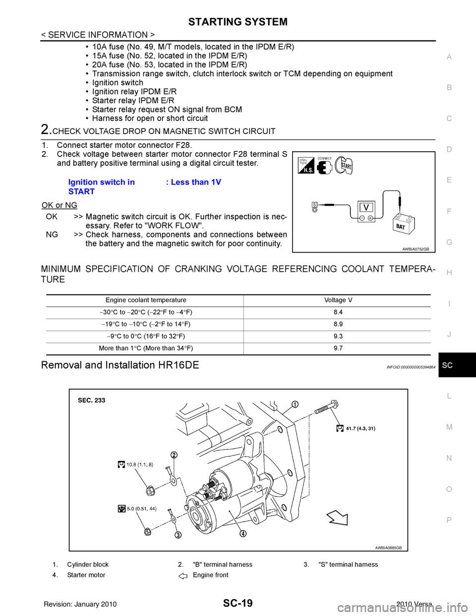
2.CHECK VOLTAGE DROP ON MAGNETIC SWITCH CIRCUIT
1. Connect starter motor connector F28.
2. Check voltage between starter motor connector F28 terminal S and battery positive terminal using a digital circuit tester.
OK or NG
OK >> Magnetic switch circuit is OK. Further inspection is nec-
essary. Refer to "WORK FLOW".
NG >> Check harness, components and connections between the battery and the magnetic switch for poor continuity.
MINIMUM SPECIFICATION OF CRANKING VO LTAGE REFERENCING COOLANT TEMPERA-
TURE
Removal and Installation HR16DEINFOID:0000000005394864
Ignition switch in
START : Less than 1V
AWBIA0752GB
Engine coolant temperature
Voltage V
− 30 °C to − 20°C ( −22 °F to −4 °F) 8.4
− 19 °C to − 10°C ( −2°F to 14 °F) 8.9
− 9 °C to 0 °C (16 °F to 32 °F) 9.3
More than 1 °C (More than 34 °F) 9.7
1. Cylinder block2. "B" terminal harness3. "S" terminal harness
4. Starter motor Engine front
AWBIA0885GB
Revision: January 20102010 Versa
Page 3710 of 3745

FRONT WIPER AND WASHER SYSTEMWW-5
< SERVICE INFORMATION >
C
DE
F
G H
I
J
L
M A
B
WW
N
O P
FRONT WIPER AND WASHER SYSTEM
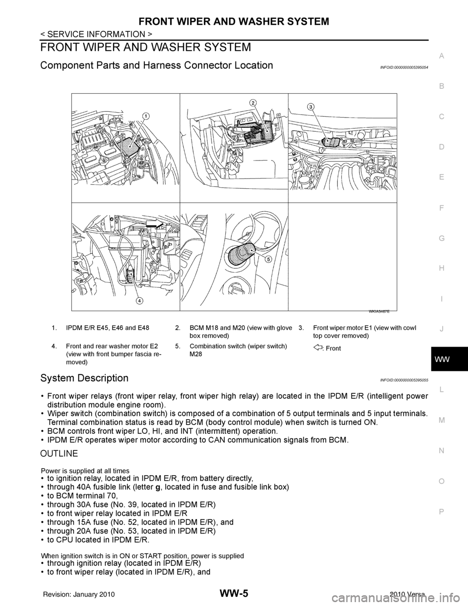
Component Parts and Har ness Connector LocationINFOID:0000000005395054
System DescriptionINFOID:0000000005395055
• Front wiper relays (front wiper relay, front wiper high relay) are located in the IPDM E/R (intelligent power
distribution module engine room).
• Wiper switch (combination switch) is composed of a combination of 5 output terminals and 5 input terminals.
Terminal combination status is read by BCM (body control module) when switch is turned ON.
• BCM controls front wiper LO, HI, and INT (intermittent) operation.
• IPDM E/R operates wiper motor accordi ng to CAN communication signals from BCM.
OUTLINE
Power is supplied at all times• to ignition relay, located in IPDM E/R, from battery directly,
• through 40A fusible link (letter g, located in fuse and fusible link box)
• to BCM terminal 70,
• through 30A fuse (No. 39, located in IPDM E/R)
• to front wiper relay located in IPDM E/R
• through 15A fuse (No. 52, located in IPDM E/R), and
• through 20A fuse (No. 53, located in IPDM E/R)
• to CPU located in IPDM E/R.
When ignition switch is in ON or START position, power is supplied • through ignition relay (located in IPDM E/R)
• to front wiper relay (located in IPDM E/R), and
1. IPDM E/R E45, E46 and E48 2. BCM M18 and M20 (view with glove
box removed)3. Front wiper motor E1
(view with cowl
top cover removed)
4. Front and rear washer motor E2 (view with front bumper fascia re-
moved) 5. Combination switch (wiper switch)
M28 : Front
WKIA5467E
Revision: January 20102010 Versa
Page 3711 of 3745

WW-6
< SERVICE INFORMATION >
FRONT WIPER AND WASHER SYSTEM
• to front wiper high relay (located in IPDM E/R), and
• to CPU (located in IPDM E/R),
• through 10A fuse [No. 6, located in fuse block (J/B)]
• to BCM terminal 38,
• through 15A fuse [No. 4, located in fuse block (J/B)]
• to combination switch terminal 14.
Ground is supplied
• to IPDM E/R terminals 39 and 59, and
• to front wiper motor terminal 2
• through grounds E15 and E24
• to BCM terminal 67, and
• to combination switch terminal 12
• through grounds M57 and M61.
LOW SPEED WIPER OPERATION
When the front wiper switch is in LO position, the BCM detects the low speed wiper ON signal by means of the
BCM wiper switch reading function.
The BCM sends a front wiper request signal (LO) through the CAN communication line
• from BCM terminals 39 and 40
• to IPDM E/R terminals 40 and 41.
When the IPDM E/R receives front wiper request signal (LO) , it turns ON front wiper relay, located in IPDM E/
R, power is supplied
• through IPDM E/R terminal 33 and front wiper high relay and front wiper relay
• to front wiper motor terminal 3.
Ground is supplied
• to front wiper motor terminal 2
• through grounds E15 and E24.
With power and ground is supplied, front wiper motor operates at low speed.
HIGH SPEED WIPER OPERATION
When the front wiper switch is in HI position, the BCM detects a high speed wiper ON signal by means of the
BCM wiper switch reading function.
The BCM sends a front wiper request signal (HI) through the CAN communication line
• from BCM terminals 39 and 40
• to IPDM E/R terminals 40 and 41.
When the IPDM E/R receives front wiper request signal (HI), it turns ON front wiper relay and front wiper high
relay, located in IPDM E/R, power is supplied
• through IPDM E/R terminal 32
• to front wiper motor terminal 5.
Ground is supplied
• to front wiper motor terminal 2
• through grounds E15 and E24.
With power and ground is supplied, front wiper motor operates at high speed.
INTERMITTENT OPERATION
Wiper intermittent operation delay interval is determined from the intermittent wiper dial position inputs. During
each intermittent operation delay interval, the BCM s ends a front wiper request signal to the IPDM E/R to
operate the wipers.
When the ignition switch is in the ON or START position, and the front wiper switch is turned to the intermittent
position, the BCM detects a front wiper (intermittent) ON signal by means of the BCM wiper switch reading
function.
BCM then sends front wiper (intermittent) request signal through the CAN communication lines
• from BCM terminals 39 and 40
• to IPDM E/R terminals 40 and 41.
When BCM determines that combination switch status is front wiper intermittent ON, it performs the following
operations.
• BCM detects ON/OFF status of intermittent wiper dial position
• BCM calculates operation interval from wiper dial position.
• BCM sends a front wiper request signal (INT) to IPDM E/R at calculated operation interval.
When IPDM E/R receives the front wiper request signal (INT), it supplies ground to energize the front wiper
relay. It then sends auto-stop signal to the BCM and conducts intermittent front wiper motor operation.
Revision: January 20102010 Versa
Page 3719 of 3745

WW-14
< SERVICE INFORMATION >
FRONT WIPER AND WASHER SYSTEM
Front Wiper Does Not Operate
INFOID:0000000005395065
CAUTION:
• During IPDM E/R fail-safe control, fr ont wipers may not operate. Refer to PG-17, "
System Descrip-
tion" in “PG IPDM E/R” to make sure that it is not in fail-safe status.
1.ACTIVE TEST
With CONSULT-lIl
1. Select “IPDM E/R” on CONSULT-III, and sele ct “ACTIVE TEST” on “SELECT DIAG MODE” screen.
2. Select “FRONT WIPER” on “SELECT TEST ITEM” screen.
3. Touch “LO” or “HI” screen.
Without CONSULT-lIl
Start up auto active test. Refer to PG-20, "
Auto Active Test" .
Does front wiper operate normally?
YES >> GO TO 2.
NO >> GO TO 4.
2.CHECK CIRCUIT BETWEEN COMB INATION SWITCH AND BCM
With CONSULT-llI
1. Select “BCM” on CONSULT-III, and sele ct “WIPER” on “SELECT TEST ITEM” screen.
2. Select “DATA MONITOR” on “SELECT DIAG MODE ” screen. Make sure that “FR WIPER INT”, “FR
WIPER LOW”, and “FR WIPER HI” turn ON-OFF according to wiper switch operation.
Without CONSULT-lIl
Refer to LT-66, "
Combination Switch Inspection" .
OK or NG
OK >> GO TO 3.
NG >> Check combination switch (wiper switch). Refer to LT-66, "
Combination Switch Inspection" .
3.CHECK CIRCUIT BETWEEN IPDM E/R AND BCM
Select “BCM” on CONSULT-III, and perform self-diagnosis for “BCM”.
Displayed self
-diagnosis results
NO DTC>>Replace BCM. Refer to BCS-19, "Removal and Installation of BCM" .
CAN COMM CIRCUIT>>Check CAN communi cation line of BCM. Refer to BCS-18, "
CAN Communication
Inspection Using CONSULT-III (Self-Diagnosis)" .
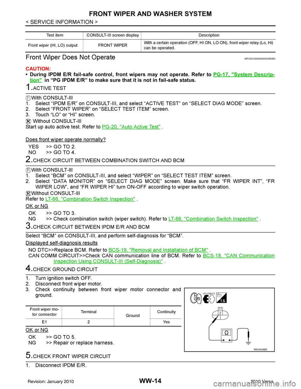
4.CHECK GROUND CIRCUIT
1. Turn ignition switch OFF.
2. Disconnect front wiper motor.
3. Check continuity between front wiper motor connector and ground.
OK or NG
OK >> GO TO 5.
NG >> Repair or replace harness.
5.CHECK FRONT WIPER CIRCUIT
1. Disconnect IPDM E/R.
Test item CONSULT-III screen display Description
Front wiper (HI, LO) output FRONT WIPER With a certain operation (OFF, HI ON,
LO ON), front wiper relay (Lo, Hi)
can be operated.
Front wiper mo- tor connector Te r m i n a l
GroundContinuity
E1 2 Yes
WKIA5488E
Revision: January 20102010 Versa