2010 NISSAN LATIO steering wheel
[x] Cancel search: steering wheelPage 1720 of 3745
ECM
EC-455
< ECU DIAGNOSIS > [HR16DE]
C
D
E
F
G H
I
J
K L
M A
EC
NP
O
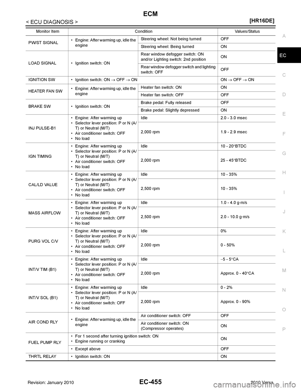
PW/ST SIGNAL
• Engine: After warming up, idle the
engine Steering wheel: Not being turned OFF
Steering wheel: Being turned
ON
LOAD SIGNAL • Ignition switch: ON Rear window defogger switch: ON
and/or Lighting switch: 2nd position
ON
Rear window defogger switch and lighting
switch: OFF OFF
IGNITION SW • Ignition switch: ON → OFF → ON ON → OFF → ON
HEATER FAN SW • Engine: After warming up, idle the
engine Heater fan switch: ON
ON
Heater fan switch: OFF OFF
BRAKE SW • Ignition switch: ON Brake pedal: Fully released
OFF
Brake pedal: Slightly depressed ON
INJ PULSE-B1 • Engine: After warming up
• Selector lever position: P or N (A/
T) or Neutral (M/T)
• Air conditioner switch: OFF
•No load Idle
2.0 - 3.0 msec
2,000 rpm 1.9 - 2.9 msec
IGN TIMING • Engine: After warming up
• Selector lever position: P or N (A/
T) or Neutral (M/T)
• Air conditioner switch: OFF
•No load Idle
10 - 20°BTDC
2,000 rpm 25 - 45°BTDC
CAL/LD VALUE • Engine: After warming up
• Selector lever position: P or N (A/
T) or Neutral (M/T)
• Air conditioner switch: OFF
•No load Idle
10 - 35%
2,500 rpm 10 - 35%
MASS AIRFLOW • Engine: After warming up
• Selector lever position: P or N (A/
T) or Neutral (M/T)
• Air conditioner switch: OFF
•No load Idle
1.0 - 4.0 g·m/s
2,500 rpm 2.0 - 10.0 g·m/s
PURG VOL C/V • Engine: After warming up
• Selector lever position: P or N (A/
T) or Neutral (M/T)
• Air conditioner switch: OFF
•No load Idle
0%
2,000 rpm 0 - 50%
INT/V TIM (B1) • Engine: After warming up
• Selector lever position: P or N (A/
T) or Neutral (M/T)
• Air conditioner switch: OFF
•No load Idle
−5 - 5 °CA
2,000 rpm Approx. 0 - 40°CA
INT/V SOL (B1) • Engine: After warming up
• Selector lever position: P or N (A/
T) or Neutral (M/T)
• Air conditioner switch: OFF
•No load Idle
0 - 2%
2,000 rpm Approx. 0 - 90%
AIR COND RLY • Engine: After warming up, idle the
engine Air conditioner switch: OFF
OFF
Air conditioner switch: ON
(Compressor operates) ON
FUEL PUMP RLY • For 1 second after turning ignition switch: ON
• Engine running or cranking
ON
• E
xcept above OFF
THRTL RELAY • Ignition switch: ON ON
Monitor Item
Condition Values/Status
Revision: January 20102010 Versa
Page 1754 of 3745
PRECAUTIONSEC-489
< PRECAUTION > [HR16DE]
C
D
E
F
G H
I
J
K L
M A
EC
NP
O
PRECAUTION
PRECAUTIONS
Precaution for Supplemental
Restraint System (SRS) "AIR BAG" and "SEAT BELT
PRE-TENSIONER"
INFOID:0000000006046361
The Supplemental Restraint System such as “AIR BAG” and “SEAT BELT PRE-TENSIONER”, used along
with a front seat belt, helps to reduce the risk or severi ty of injury to the driver and front passenger for certain
types of collision. This system includes seat belt switch inputs and dual stage front air bag modules. The SRS
system uses the seat belt switches to determine the front air bag deployment, and may only deploy one front
air bag, depending on the severity of a collision and w hether the front occupants are belted or unbelted.
Information necessary to service the system safely is included in the SRS and SB section of this Service Man-
ual.
WARNING:
• To avoid rendering the SRS inoper ative, which could increase the risk of personal injury or death in
the event of a collision which would result in air bag inflation, all maintenance must be performed by
an authorized NISSAN/INFINITI dealer.
• Improper maintenance, including in correct removal and installation of the SRS can lead to personal
injury caused by unintentional act ivation of the system. For removal of Spiral Cable and Air Bag
Module, see the SRS section.
• Do not use electrical test equipm ent on any circuit related to the SRS unless instructed to in this
Service Manual. SRS wiring harnesses can be identi fied by yellow and/or orange harnesses or har-
ness connectors.
PRECAUTIONS WHEN USING POWER TOOLS (AIR OR ELECTRIC) AND HAMMERS
WARNING:
• When working near the Airbag Diagnosis Sensor Un it or other Airbag System sensors with the Igni-
tion ON or engine running, DO NOT use air or el ectric power tools or strike near the sensor(s) with a
hammer. Heavy vibration could activate the sensor( s) and deploy the air bag(s), possibly causing
serious injury.
• When using air or electric power tools or hammers, always switch the Ignition OFF, disconnect the battery, and wait at least 3 minutes before performing any service.
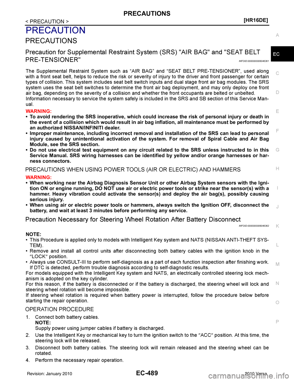
Precaution Necessary for Steering Wheel Rotation After Battery Disconnect
INFOID:0000000006046362
NOTE:
• This Procedure is applied only to models with Intelligent Key system and NATS (NISSAN ANTI-THEFT SYS-
TEM).
• Remove and install all control units after disconnecti ng both battery cables with the ignition knob in the
″ LOCK ″ position.
• Always use CONSULT-III to perform self-diagnosis as a part of each function inspection after finishing work.
If DTC is detected, perform trouble diagnosis according to self-diagnostic results.
For models equipped with the Intelligent Key system and NATS , an electrically controlled steering lock mech-
anism is adopted on the key cylinder.
For this reason, if the battery is disconnected or if the battery is discharged, the steering wheel will lock and
steering wheel rotation will become impossible.
If steering wheel rotation is required when battery power is interrupted, follow the procedure below before
starting the repair operation.
OPERATION PROCEDURE
1. Connect both battery cables. NOTE:
Supply power using jumper cables if battery is discharged.
2. Use the Intelligent Key or mechanical key to turn the ignition switch to the ″ACC ″ position. At this time, the
steering lock will be released.
3. Disconnect both battery cables. The steering lock will remain released and the steering wheel can be
rotated.
4. Perform the necessary repair operation.
Revision: January 20102010 Versa
Page 1767 of 3745
EC-502
< SERVICE DATA AND SPECIFICATIONS (SDS) [HR16DE]
SERVICE DATA AND SPECIFICATIONS (SDS)
SERVICE DATA AND SPECIFICATIONS (SDS)
SERVICE DATA AND SPECIFICATIONS (SDS)
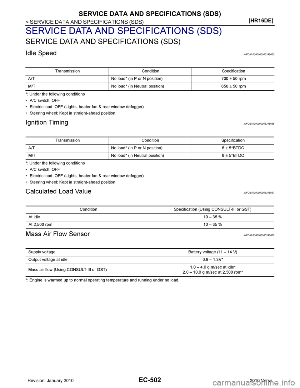
Idle SpeedINFOID:0000000005398655
*: Under the following conditions
• A/C switch: OFF
• Electric load: OFF (Lights, heater fan & rear window defogger)
• Steering wheel: Kept in straight-ahead position
Ignition TimingINFOID:0000000005398656
*: Under the following conditions
• A/C switch: OFF
• Electric load: OFF (Lights, heater fan & rear window defogger)
• Steering wheel: Kept in straight-ahead position
Calculated Load ValueINFOID:0000000005398657
Mass Air Flow SensorINFOID:0000000005398658
*: Engine is warmed up to normal operating temperature and running under no load.Transmission
ConditionSpecification
A/T No load* (in P or N position) 700 ± 50 rpm
M/T No load* (in Neutral position) 650 ± 50 rpm
Transmission ConditionSpecification
A/T No load* (in P or N position) 6 ± 5 °BTDC
M/T No load* (in Neutral position) 6 ± 5 °BTDC
Condition Specification (Using CONSULT-III or GST)
At idle 10 – 35 %
At 2,500 rpm 10 – 35 %
Supply voltageBattery voltage (11 – 14 V)
Output voltage at idle 0.9 – 1.3V*
Mass air flow (Using CONSULT-III or GST) 1.0 – 4.0 g·m/sec at idle*
2.0 – 10.0 g·m/sec at 2,500 rpm*
Revision: January 20102010 Versa
Page 1774 of 3745
PRECAUTIONSEC-509
< SERVICE INFORMATION > [MR18DE]
C
D
E
F
G H
I
J
K L
M A
EC
NP
O
PRECAUTIONS
Precaution for Supplemental
Restraint System (SRS) "AIR BAG" and "SEAT BELT
PRE-TENSIONER"
INFOID:0000000006046363
The Supplemental Restraint System such as “AIR BAG” and “SEAT BELT PRE-TENSIONER”, used along
with a front seat belt, helps to reduce the risk or severi ty of injury to the driver and front passenger for certain
types of collision. This system includes seat belt switch inputs and dual stage front air bag modules. The SRS
system uses the seat belt switches to determine the front air bag deployment, and may only deploy one front
air bag, depending on the severity of a collision and w hether the front occupants are belted or unbelted.
Information necessary to service the system safely is included in the SRS and SB section of this Service Man-
ual.
WARNING:
• To avoid rendering the SRS inoper ative, which could increase the risk of personal injury or death in
the event of a collision which would result in air bag inflation, all maintenance must be performed by
an authorized NISSAN/INFINITI dealer.
• Improper maintenance, including in correct removal and installation of the SRS can lead to personal
injury caused by unintentional act ivation of the system. For removal of Spiral Cable and Air Bag
Module, see the SRS section.
• Do not use electrical test equipm ent on any circuit related to the SRS unless instructed to in this
Service Manual. SRS wiring harnesses can be identi fied by yellow and/or orange harnesses or har-
ness connectors.
PRECAUTIONS WHEN USING POWER TOOLS (AIR OR ELECTRIC) AND HAMMERS
WARNING:
• When working near the Airbag Diagnosis Sensor Un it or other Airbag System sensors with the Igni-
tion ON or engine running, DO NOT use air or el ectric power tools or strike near the sensor(s) with a
hammer. Heavy vibration could activate the sensor( s) and deploy the air bag(s), possibly causing
serious injury.
• When using air or electric power tools or hammers, always switch the Ignition OFF, disconnect the battery, and wait at least 3 minutes before performing any service.
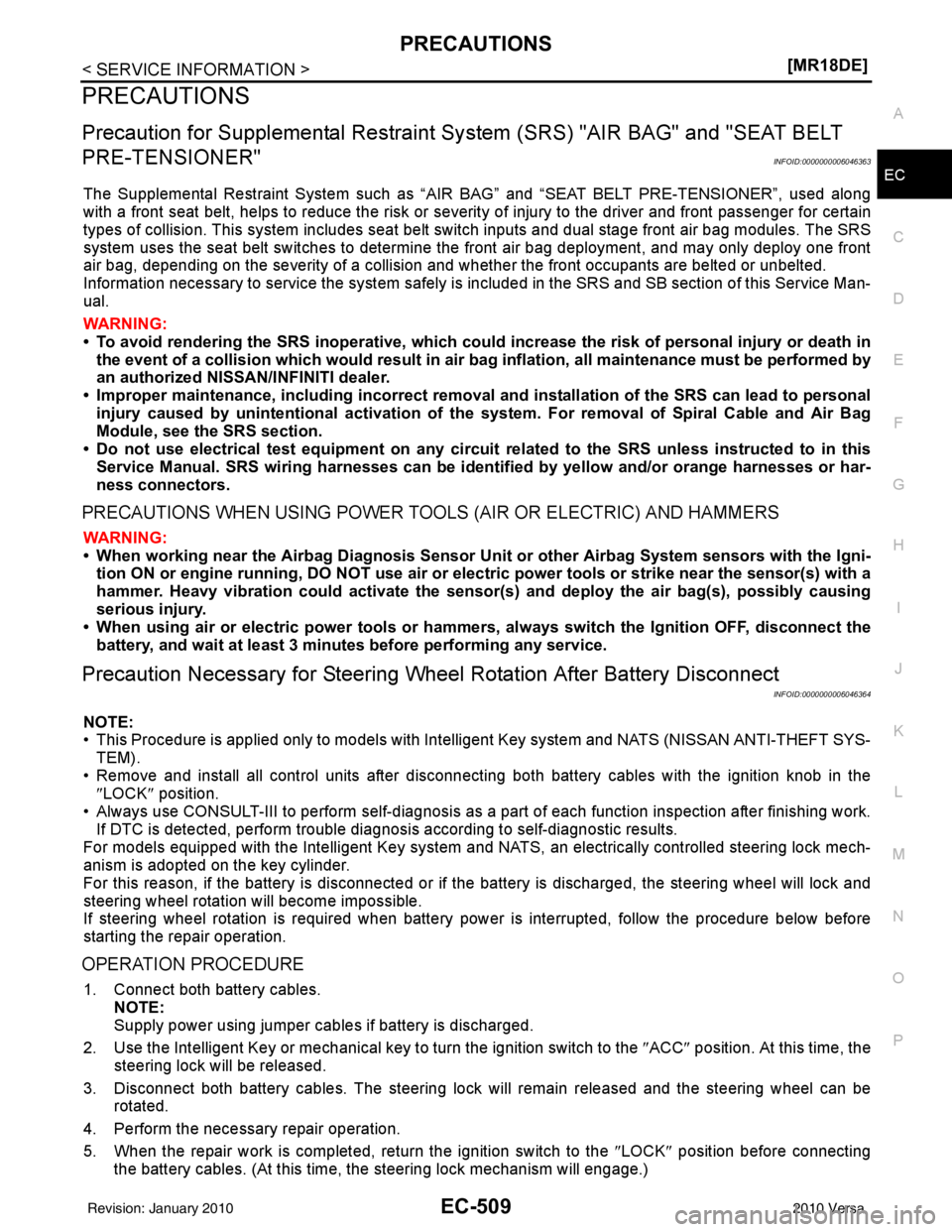
Precaution Necessary for Steering Wheel Rotation After Battery Disconnect
INFOID:0000000006046364
NOTE:
• This Procedure is applied only to models with Intelligent Key system and NATS (NISSAN ANTI-THEFT SYS-
TEM).
• Remove and install all control units after disconnecti ng both battery cables with the ignition knob in the
″ LOCK ″ position.
• Always use CONSULT-III to perform self-diagnosis as a part of each function inspection after finishing work.
If DTC is detected, perform trouble diagnosis according to self-diagnostic results.
For models equipped with the Intelligent Key system and NATS , an electrically controlled steering lock mech-
anism is adopted on the key cylinder.
For this reason, if the battery is disconnected or if the battery is discharged, the steering wheel will lock and
steering wheel rotation will become impossible.
If steering wheel rotation is required when battery power is interrupted, follow the procedure below before
starting the repair operation.
OPERATION PROCEDURE
1. Connect both battery cables.
NOTE:
Supply power using jumper cables if battery is discharged.
2. Use the Intelligent Key or mechanical key to turn the ignition switch to the ″ACC ″ position. At this time, the
steering lock will be released.
3. Disconnect both battery cables. The steering lock will remain released and the steering wheel can be
rotated.
4. Perform the necessary repair operation.
5. When the repair work is completed, return the ignition switch to the ″LOCK ″ position before connecting
the battery cables. (At this time, the steering lock mechanism will engage.)
Revision: January 20102010 Versa
Page 1839 of 3745
EC-574
< SERVICE INFORMATION >[MR18DE]
BASIC SERVICE PROCEDURE
BASIC SERVICE PROCEDURE
Basic InspectionINFOID:0000000005532404
1.INSPECTION START
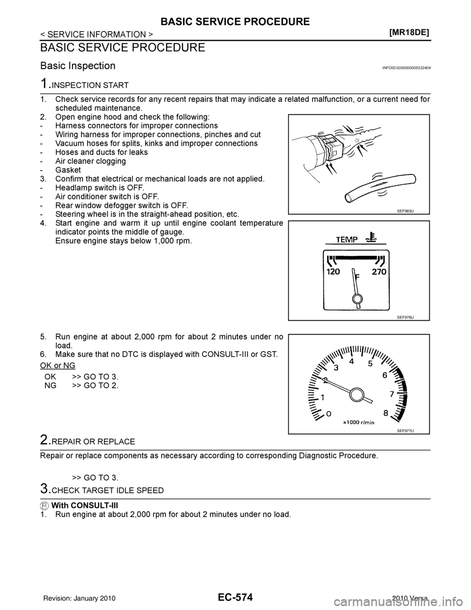
1. Check service records for any recent repairs that ma y indicate a related malfunction, or a current need for
scheduled maintenance.
2. Open engine hood and check the following:
- Harness connectors for improper connections
- Wiring harness for improper connections, pinches and cut
- Vacuum hoses for splits, kinks and improper connections
- Hoses and ducts for leaks
- Air cleaner clogging
- Gasket
3. Confirm that electrical or mechanical loads are not applied.
- Headlamp switch is OFF.
- Air conditioner switch is OFF.
- Rear window defogger switch is OFF.
- Steering wheel is in the straight-ahead position, etc.
4. Start engine and warm it up until engine coolant temperature indicator points the middle of gauge.
Ensure engine stays below 1,000 rpm.
5. Run engine at about 2,000 rpm for about 2 minutes under no load.
6. Make sure that no DTC is displayed with CONSULT-III or GST.
OK or NG
OK >> GO TO 3.
NG >> GO TO 2.
2.REPAIR OR REPLACE
Repair or replace components as necessary according to corresponding Diagnostic Procedure.
>> GO TO 3.
3.CHECK TARGET IDLE SPEED
With CONSULT-III
1. Run engine at about 2,000 rpm for about 2 minutes under no load.
SEF983U
SEF976U
SEF977U
Revision: January 20102010 Versa
Page 1846 of 3745
BASIC SERVICE PROCEDUREEC-581
< SERVICE INFORMATION > [MR18DE]
C
D
E
F
G H
I
J
K L
M A
EC
NP
O
• Electric load switch: OFF
[Air conditioner, headlamp, rear window defogger]
On vehicles equipped with daytime light systems, if the parking brake is applied before the engine is
started the headlamp will not be illuminated.
• Steering wheel: Neutral (Straight-ahead position)
• Vehicle speed: Stopped
• Transmission: Warmed-up
- Models with CONSULT-III (A/T and CVT models)
• Drive vehicle until “FLUID TEMP SE” in “DATA MONI TOR” mode of “A/T” or “CVT” system indicates less
than 0.9 V.
- Models without CONSULT-III (A/T and CVT models) and M/T models
• Drive vehicle for 10 minutes.
OPERATION PROCEDURE
With CONSULT-III
1. Perform EC-580, "Accelerator Pedal Released Position Learning".
2. Perform EC-580, "
Throttle Valve Closed Position Learning".
3. Start engine and warm it up to normal operating temperature.
4. Check that all items listed under the topic PREP ARATION (previously mentioned) are in good order.
5. Select “IDLE AIR VOL LEA RN” in “WORK SUPPORT” mode.
6. Touch “START” and wait 20 seconds.
7. Make sure that “CMPLT” is displayed on CONSULT-III screen. If “CMPLT” is not displayed, Idle Air Vol-
ume Learning will not be carried out successfully. In this case, find the cause of the incident by referring to
the DIAGNOSTIC PROCEDURE below.
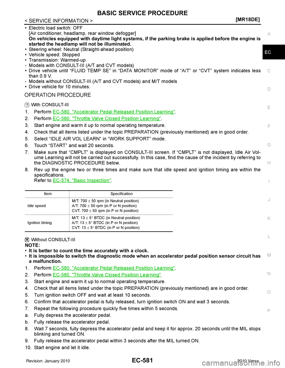
8. Rev up the engine two or three times and make sure that idle speed and ignition timing are within the specifications.
Refer to EC-574, "
Basic Inspection".
Without CONSULT-III
NOTE:
•It is better to count the time accurately with a clock.
• It is impossible to switch the di agnostic mode when an accelerator pedal position sensor circuit has
a malfunction.
1. Perform EC-580, "
Accelerator Pedal Released Position Learning".
2. Perform EC-580, "
Throttle Valve Closed Position Learning".
3. Start engine and warm it up to normal operating temperature.
4. Check that all items listed under the topic PREP ARATION (previously mentioned) are in good order.
5. Turn ignition switch OFF and wait at least 10 seconds.
6. Confirm that accelerator pedal is fully releas ed, turn ignition switch ON and wait 3 seconds.
7. Repeat the following procedure quick ly five times within 5 seconds.
a. Fully depress the accelerator pedal.
b. Fully release the accelerator pedal.
8. Wait 7 seconds, fully depress the accelerator pedal and keep it for approx. 20 seconds until the MIL stops blinking and turned ON.
9. Fully release the accelerator pedal within 3 seconds after the MIL turned ON.
10. Start engine and let it idle.
Item Specification
Idle speed M/T: 700
± 50 rpm (in Neutral position)
A/T: 700 ± 50 rpm (in P or N position)
CVT: 700 ± 50 rpm (in P or N position)
Ignition timing M/T: 13
± 5 ° BTDC (in Neutral position)
A/T: 13 ± 5° BTDC (in P or N position)
CVT: 13 ± 5 ° BTDC (in P or N position)
Revision: January 20102010 Versa
Page 1886 of 3745
TROUBLE DIAGNOSISEC-621
< SERVICE INFORMATION > [MR18DE]
C
D
E
F
G H
I
J
K L
M A
EC
NP
O
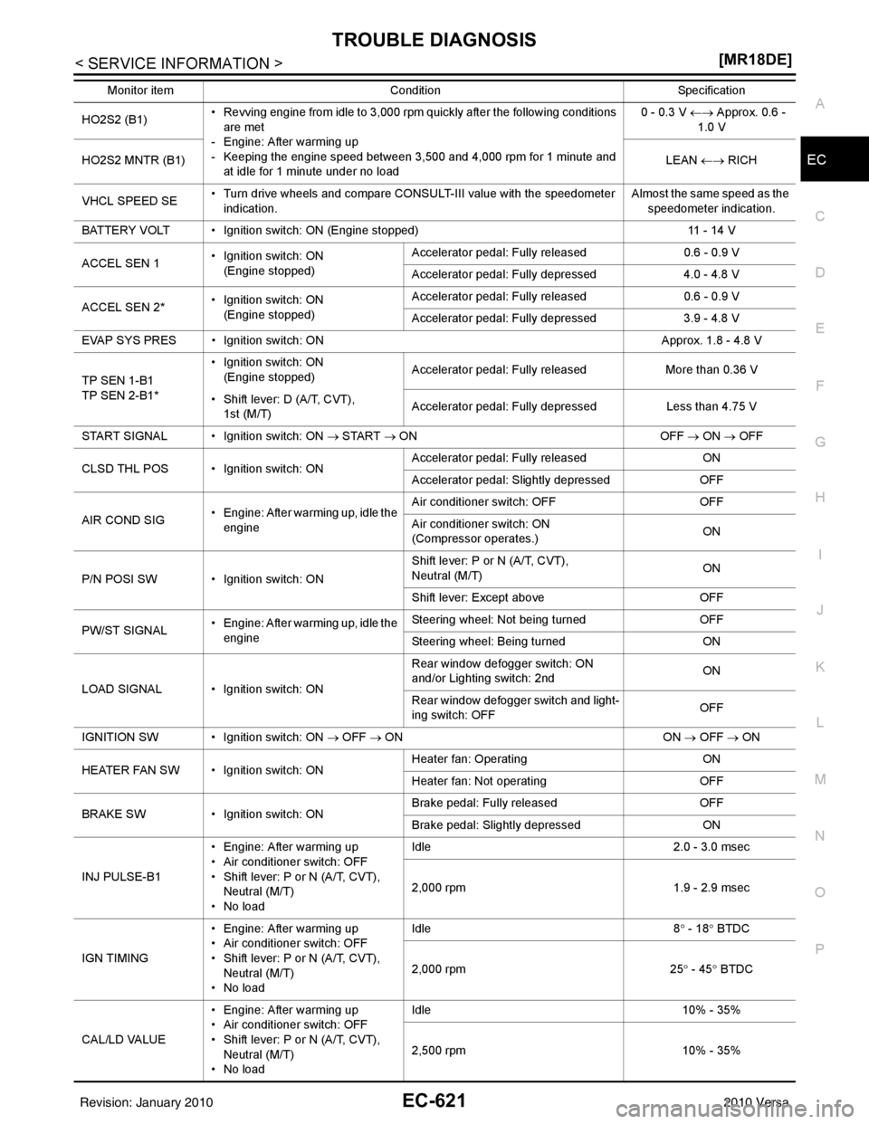
HO2S2 (B1)
• Revving engine from idle to 3,000 rpm quickly after the following conditions
are met
- Engine: After warming up
- Keeping the engine speed between 3,500 and 4,000 rpm for 1 minute and at idle for 1 minute under no load 0 - 0.3 V
←→ Approx. 0.6 -
1.0 V
HO2S2 MNTR (B1) LEAN ←→ RICH
VHCL SPEED SE • Turn drive wheels and compare CONSULT-III value with the speedometer
indication. Almost the same speed as the
speedometer indication.
BATTERY VOLT • Ignition switch: ON (Engine stopped) 11 - 14 V
ACCEL SEN 1 • Ignition switch: ON
(Engine stopped) Accelerator pedal: Fully released
0.6 - 0.9 V
Accelerator pedal: Fully depressed 4.0 - 4.8 V
ACCEL SEN 2* • Ignition switch: ON
(Engine stopped) Accelerator pedal: Fully released
0.6 - 0.9 V
Accelerator pedal: Fully depressed 3.9 - 4.8 V
EVAP SYS PRES • Ignition switch: ON Approx. 1.8 - 4.8 V
TP SEN 1-B1
TP SEN 2-B1* • Ignition switch: ON
(Engine stopped) Accelerator pedal: Fully released
More than 0.36 V
• Shift lever: D (A/T, CVT), 1st (M/T) Accelerator pedal: Fully depressed
Less than 4.75 V
START SIGNAL • Ignition switch: ON → START → ON OFF → ON → OFF
CLSD THL POS • Ignition switch: ON Accelerator pedal: Fully released
ON
Accelerator pedal: Slightly depressed OFF
AIR COND SIG • Engine: After warming up, idle the
engine Air conditioner switch: OFF
OFF
Air conditioner switch: ON
(Compressor operates.) ON
P/N POSI SW • Ignition switch: ON Shift lever: P or N (A/T, CVT),
Neutral (M/T)
ON
Shift lever: Except above OFF
PW/ST SIGNAL • Engine: After warming up, idle the
engine Steering wheel: Not being turned
OFF
Steering wheel: Being turned ON
LOAD SIGNAL • Ignition switch: ON Rear window defogger switch: ON
and/or Lighting switch: 2nd
ON
Rear window defogger switch and light-
ing switch: OFF OFF
IGNITION SW • Ignition switch: ON → OFF → ON ON → OFF → ON
HEATER FAN SW • Ignition switch: ON Heater fan: Operating
ON
Heater fan: Not operating OFF
BRAKE SW • Ignition switch: ON Brake pedal: Fully released
OFF
Brake pedal: Slightly depressed ON
INJ PULSE-B1 • Engine: After warming up
• Air conditioner switch: OFF
• Shift lever: P or N (A/T, CVT),
Neutral (M/T)
•No load Idle
2.0 - 3.0 msec
2,000 rpm 1.9 - 2.9 msec
IGN TIMING • Engine: After warming up
• Air conditioner switch: OFF
• Shift lever: P or N (A/T, CVT),
Neutral (M/T)
•No load Idl
e
8° -
18
° BTDC
2,000 rpm 25° - 45 ° BTDC
CAL/LD VALUE • Engine: After warming up
• Air conditioner switch: OFF
• Shift lever: P or N (A/T, CVT),
Neutral (M/T)
•No load Idle
10% - 35%
2,500 rpm 10% - 35%
Monitor item
Condition Specification
Revision: January 20102010 Versa
Page 1889 of 3745
EC-624
< SERVICE INFORMATION >[MR18DE]
TROUBLE DIAGNOSIS - SPECIFICATION VALUE
TROUBLE DIAGNOSIS - SPECIFICATION VALUE
DescriptionINFOID:0000000005532424
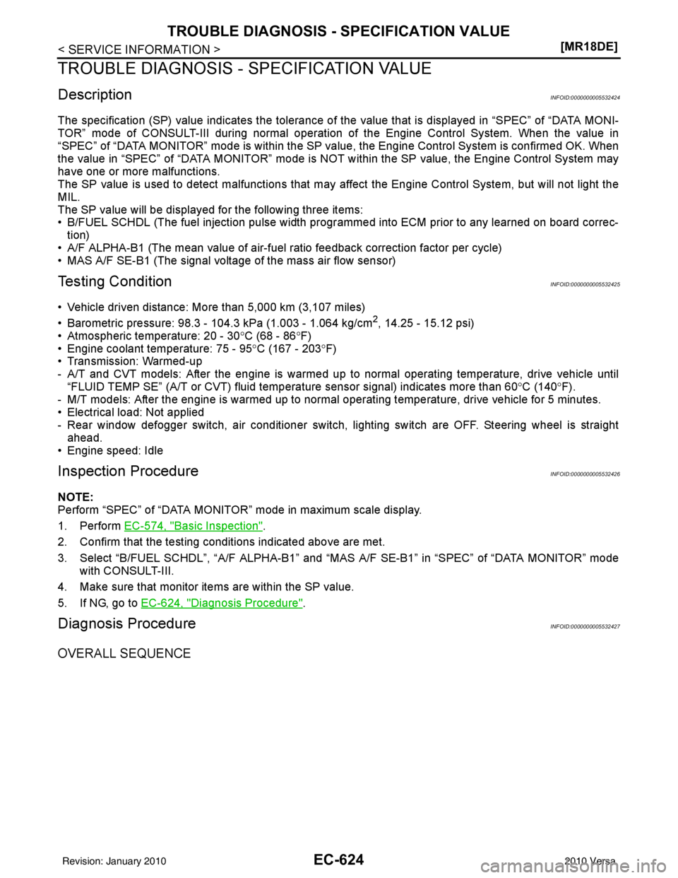
The specification (SP) value indicates the tolerance of
the value that is displayed in “SPEC” of “DATA MONI-
TOR” mode of CONSULT-III during normal operation of the Engine Control System. When the value in
“SPEC” of “DATA MONITOR” mode is within the SP value, the Engine Control System is confirmed OK. When
the value in “SPEC” of “DATA MONITOR” mode is NOT within the SP value, the Engine Control System may
have one or more malfunctions.
The SP value is used to detect malfunctions that may af fect the Engine Control System, but will not light the
MIL.
The SP value will be displayed for the following three items:
• B/FUEL SCHDL (The fuel injection pulse width progr ammed into ECM prior to any learned on board correc-
tion)
• A/F ALPHA-B1 (The mean value of air-fuel ratio feedback correction factor per cycle)
• MAS A/F SE-B1 (The signal voltage of the mass air flow sensor)
Testing ConditionINFOID:0000000005532425
• Vehicle driven distance: More than 5,000 km (3,107 miles)
• Barometric pressure: 98.3 - 104.3 kPa (1.003 - 1.064 kg/cm
2, 14.25 - 15.12 psi)
• Atmospheric temperature: 20 - 30 °C (68 - 86° F)
• Engine coolant temperature: 75 - 95 °C (167 - 203° F)
• Transmission: Warmed-up
- A/T and CVT models: After the engine is warmed up to normal operating temperature, drive vehicle until
“FLUID TEMP SE” (A/T or CVT) fluid temperature sensor signal) indicates more than 60 °C (140° F).
- M/T models: After the engine is warmed up to normal operating temperature, drive vehicle for 5 minutes.
• Electrical load: Not applied
- Rear window defogger switch, air conditioner switch, lighting switch are OFF. Steering wheel is straight ahead.
• Engine speed: Idle
Inspection ProcedureINFOID:0000000005532426
NOTE:
Perform “SPEC” of “DATA MONITOR” mode in maximum scale display.
1. Perform EC-574, "
Basic Inspection".
2. Confirm that the testing conditions indicated above are met.
3. Select “B/FUEL SCHDL”, “A/F ALPHA-B1” and “MAS A/F SE-B1” in “SPEC” of “DATA MONITOR” mode
with CONSULT-III.
4. Make sure that monitor items are within the SP value.
5. If NG, go to EC-624, "
Diagnosis Procedure".
Diagnosis ProcedureINFOID:0000000005532427
OVERALL SEQUENCE
Revision: January 20102010 Versa