Page 304 of 422

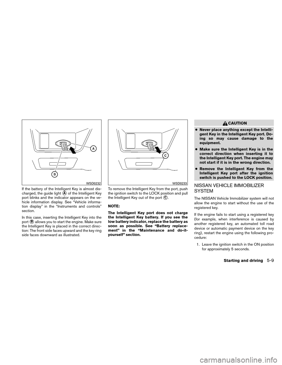
If the battery of the Intelligent Key is almost dis-
charged, the guide light
�Aof the Intelligent Key
port blinks and the indicator appears on the ve-
hicle information display. See “Vehicle informa-
tion display” in the “Instruments and controls”
section.
In this case, inserting the Intelligent Key into the
port
�Ballows you to start the engine. Make sure
the Intelligent Key is placed in the correct direc-
tion: The front side faces upward and the key ring
side faces downward as illustrated. To remove the Intelligent Key from the port, push
the ignition switch to the LOCK position and pull
the Intelligent Key out of the port
�C.
NOTE:
The Intelligent Key port does not charge
the Intelligent Key battery. If you see the
low battery indicator, replace the battery as
soon as possible. See “Battery replace-
ment” in the “Maintenance and do-it-
yourself” section.
CAUTION
● Never place anything except the Intelli-
gent Key in the Intelligent Key port. Do-
ing so may cause damage to the
equipment.
● Make sure the Intelligent Key is in the
correct direction when inserting it to
the Intelligent Key port. The engine may
not start if it is in the wrong direction.
● Remove the Intelligent Key from the
Intelligent Key port after the ignition
switch is pushed to the LOCK position.
NISSAN VEHICLE IMMOBILIZER
SYSTEM
The NISSAN Vehicle Immobilizer system will not
allow the engine to start without the use of the
registered key.
If the engine fails to start using a registered key
(for example, when interference is caused by
another registered key, an automated toll road
device or automatic payment device on the key
ring) , restart the engine using the following pro-
cedure:
1. Leave the ignition switch in the ON position for approximately 5 seconds.
WSD0232WSD0233
Starting and driving5-9
Page 330 of 422

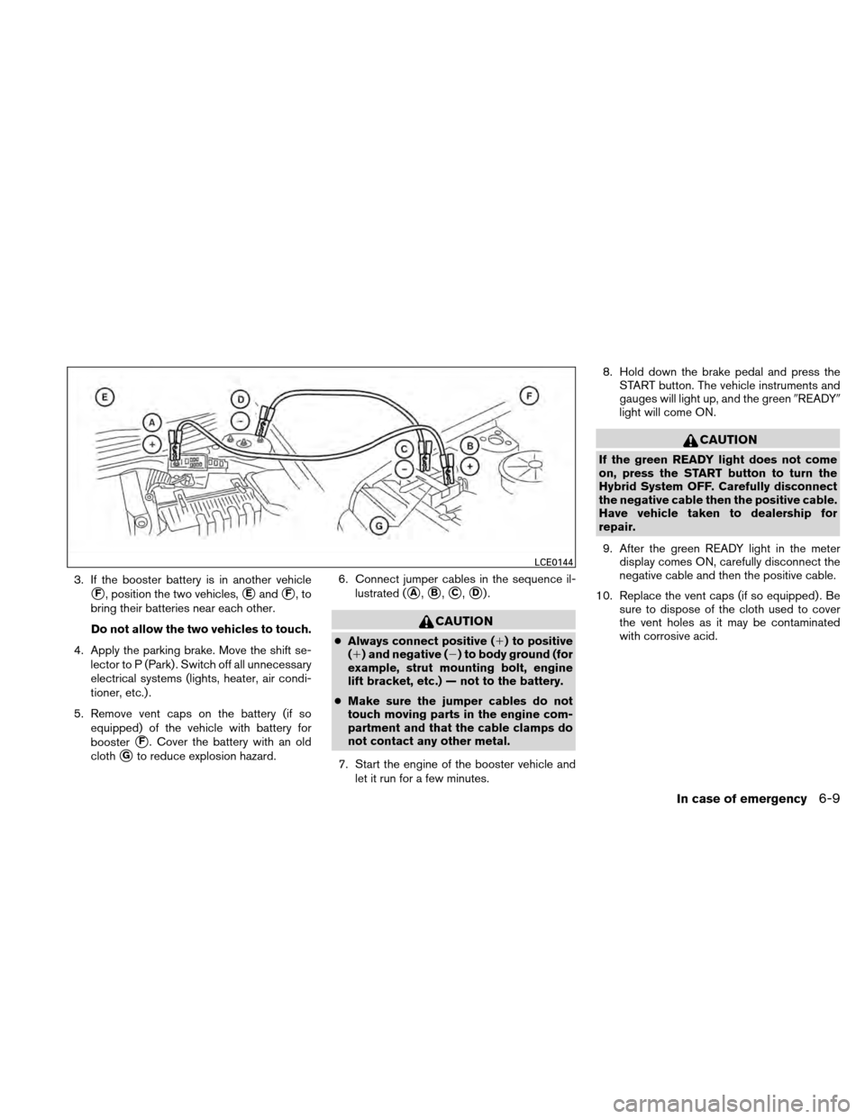
3. If the booster battery is in another vehicle
�F, position the two vehicles,�Eand�F,to
bring their batteries near each other.
Do not allow the two vehicles to touch.
4. Apply the parking brake. Move the shift se- lector to P (Park) . Switch off all unnecessary
electrical systems (lights, heater, air condi-
tioner, etc.) .
5. Remove vent caps on the battery (if so equipped) of the vehicle with battery for
booster
�F. Cover the battery with an old
cloth
�Gto reduce explosion hazard. 6. Connect jumper cables in the sequence il-
lustrated (
�A,�B,�C,�D).
CAUTION
●Always connect positive (�) to positive
(�) and negative (�) to body ground (for
example, strut mounting bolt, engine
lift bracket, etc.) — not to the battery.
● Make sure the jumper cables do not
touch moving parts in the engine com-
partment and that the cable clamps do
not contact any other metal.
7. Start the engine of the booster vehicle and let it run for a few minutes. 8. Hold down the brake pedal and press the
START button. The vehicle instruments and
gauges will light up, and the green �READY�
light will come ON.
CAUTION
If the green READY light does not come
on, press the START button to turn the
Hybrid System OFF. Carefully disconnect
the negative cable then the positive cable.
Have vehicle taken to dealership for
repair.
9. After the green READY light in the meter display comes ON, carefully disconnect the
negative cable and then the positive cable.
10. Replace the vent caps (if so equipped) . Be sure to dispose of the cloth used to cover
the vent holes as it may be contaminated
with corrosive acid.
LCE0144
In case of emergency6-9
Page 415 of 422

Precautions on child
restraints.........1-17, 1-23, 1-28, 1-31
Top tether strap anchor point locations . .1-21
Child safety rear door lock ............3-6
Chimes, audible reminders ...........2-17
Cleaning exterior and interior ...........7-2
Clock ...................4-39, 4-44
(models with navigation system) .......4-8
(models without navigation system) . . . .4-39
Clock set ..................4-8, 4-39
C.M.V.S.S. certification label ..........9-10
Cold weather driving ..............5-24
Compact disc (CD)
player ............4-40, 4-46, 4-52, 4-58
Compass display .................2-6
Console box ...................2-38
Console light ...................2-45
Continuously Variable Transmission (CVT) Transmission selector lever lock release . .5-13
Control panel buttons ...............4-2
Brightness/contrast button .........4-12
Enter button ..................4-2
Setting button .................4-6
Controls Heater and air conditioner controls .....4-20
Coolant Capacities and recommended
fuel/lubricants .................9-2
Changing engine coolant ...........8-9
Checking engine coolant level ........8-8
Checking inverter coolant level .......8-10
Corrosion protection ...............7-6
Cruise control ..................5-15
Cup holders ...................2-37 D
Daytime running light system (Canada only) . .2-31
Defroster switch Rear window and outside mirror defroster
switch .....................2-29
Digital Versatile Disc (DVD) player .......4-57
Dimensions and weights .............9-8
Dimmer switch for instrument panel ......2-32
Display controls (see control panel buttons) . .4-2
Door locks .....................3-4
Drive belt .....................8-15
Driving Cold
weather driving ............5-24
Driving with Electronically controlled
Continuously Variable Transmission
(eCVT) ....................5-11
Precautions when starting and driving . . . .5-2
E
Economy - fuel ..................5-17
Electronically controlled Continuously Variable
Transmission (eCVT) Driving with Electronically controlled
Continuously Variable Transmission
(eCVT) ....................5-11
Electronically controlled Continuously
Variable Transmission (eCVT) fluid .....8-13
Emission control information label .......9-10
Emission control system warranty .......9-24
Energy flow ...................HEV-4
Energy/fuel history ...............HEV-5 Engine
Block heater .................5-25
Capacities and recommended
fuel/lubricants .................9-2
Changing engine coolant ...........8-9
Changing engine oil .............8-11
Changing engine oil filter ..........8-12
Checking engine coolant level ........8-8
Checking engine oil level ..........8-10
Engine compartment check locations . . . .8-7
Engine cooling system ............8-8
Engine oil ...................8-10
Engine oil and oil filter recommendation . . .9-5
Engine oil pressure warning light ......2-12
Engine oil viscosity ..............9-5
Engine serial number ............9-10
Engine specifications .............9-7
Enter button ....................4-2
Event data recorders ..............9-25
Exhaust gas (Carbon monoxide) .........5-2
Eyeglass case ..................2-36
F
Flashers
(See hazard warning flasher switch) ......2-33
Flat tire .......................6-2
Floor mat positioning aid .............7-6
Fluid Brake fluid ..................8-13
Capacities
and recommended
fuel/lubricants .................9-2
Electronically controlled Continuously
Variable Transmission (eCVT) fluid .....8-13
Engine coolant .................8-8
10-2