2010 NISSAN 370Z COUPE tire type
[x] Cancel search: tire typePage 168 of 409
Black plate (168,1)
Model "Z34-D" EDITED: 2009/ 9/ 10
SAA2492
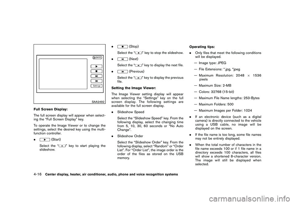
Full Screen Display:
The full screen display will appear when select-
ing the “Full Screen Display” key.
To operate the Image Viewer or to change the
settings, select the desired key using the multi-
function controller.
.
(Start)
Select the “
” key to start playing the
slideshow. .
(Stop)
Select the “
” key to stop the slideshow.
.
(Next)
Select the “
” key to display the next file.
.
(Previous)
Select the “
” key to display the previous
file.
Setting the Image Viewer:
The Image Viewer setting display will appear
when selecting the “Settings” key on the full
screen display. The following settings are
available for the full screen display.
. Slideshow Speed
Select the “Slideshow Speed” key. From the
following display, select the changing time
from 5, 10, 30, 60 seconds or “No Auto
Change”.
. Slideshow Order
Select the “Slideshow Order” key. From the
following display, select “Random” or “Order
List”. For “Order List”, the image order is the
order of the files as stored on the USB
memory. Operating tips:
.
Only files that meet the following conditions
will be displayed.
— Image type: JPEG
— File Extensions: *.jpg, *jpeg
— Maximum Resolution: 2048 61536
pixels
— Maximum Size: 2-MB
— Colors: 32768 (15-bit)
— Maximum File Name lengths: 253-Bytes
— Maximum Folders: 500
— Maximum Images per Folder: 1024
. If an electronic device (such as a digital
camera) is directly connected to the vehicle
using a USB cable, no image will be
displayed on the screen.
. If the file name is too long, some file names
may not be entirely displayed.
. When the total number of characters in the
file name exceeds 100 or if 1 file name in a
directory exceeds 100 characters, all files
will show a shortened 8-character version.
The image will still be displayed when
selected.
4-16
Center display, heater, air conditioner, audio, phone and voice recognition systems
Page 300 of 409

Black plate (300,1)
Model "Z34-D" EDITED: 2009/ 9/ 10
BRAKE ASSISTWhen the force applied to the brake pedal
exceeds a certain level, the Brake Assist is
activated generating greater braking force than a
conventional brake booster even with light pedal
force.
WARNING
The Brake Assist is only an aid to assist
braking operation and is not a collision
warning or avoidance device. It is the
driver’s responsibility to stay alert, drive
safely and be in control of the vehicle at
all times.ANTI-LOCK BRAKING SYSTEM (ABS)
WARNING
.The Anti-lock Braking System (ABS)
is a sophisticated device, but it
cannot prevent accidents resulting
from careless or dangerous driving
techniques. It can help maintain
vehicle control during braking on
slippery surfaces. Remember that
stopping distances on slippery sur-
faces will be longer than on normal
surfaces even with ABS. Stopping distances may also be longer on
rough, gravel or snow covered
roads, or if you are using tire chains.
Alwaysmaintainasafedistance
from the vehicle in front of you.
Ultimately, the driver is responsible
for safety.
. Tire type and condition may also
affect braking effectiveness.
— When replacing tires, install the
specified size of tires on all four
wheels.
— When installing a spare tire, make sure that it is the proper
size and type as specified on the
Tire and Loading Information
label. See “TIRE AND LOADING
INFORMATION LABEL” in the “9.
Technical and consumer infor-
mation” section of this manual.
— For detailed information, see “WHEELS AND TIRES” in the
“8. Maintenance and do-it-your-
self” section of this manual.
The Anti-lock Braking System (ABS) controls
the brakes so the wheels do not lock during hard
braking or when braking on slippery surfaces.
The system detects the rotation speed at each wheel and varies the brake fluid pressure to
prevent each wheel from locking and sliding. By
preventing each wheel from locking, the system
helps the driver maintain steering control and
helps to minimize swerving and spinning on
slippery surfaces.
Using the systemDepress the brake pedal and hold it down.
Depress the brake pedal with firm steady
pressure, but do not pump the brakes. The
ABS will operate to prevent the wheels from
locking up. Steer the vehicle to avoid obstacles.
WARNING
Do not pump the brake pedal. Doing so
may result in increased stopping dis-
tances.Self-test featureThe ABS includes electronic sensors, electric
pumps, hydraulic solenoids and a computer. The
computer has a built-in diagnostic feature that
tests the system each time you start the engine
and move the vehicle at a low speed in forward
or reverse. When the self-test occurs, you may
hear a “clunk” noise and/or feel a pulsation in the
brake pedal. This is normal and does not
indicate a malfunction. If the computer senses
a malfunction, it switches the ABS off and
illuminates the ABS warning light on the
BRAKE ASSIST5-26
Starting and driving
Page 302 of 409
Black plate (302,1)
Model "Z34-D" EDITED: 2009/ 9/ 10
that tests the system each time you start the
engine and move the vehicle forward or in
reverse at a slow speed. When the self-test
occurs, you may hear a “clunk” noise and/or feel
a pulsation in the brake pedal. This is normal and
is not an indication of a malfunction.
WARNING
.The VDC system is designed to help
the driver maintain stability but
does not prevent accidents due to
abrupt steering operation at high
speeds or by careless or dangerous
driving techniques. Reduce vehicle
speed and be especially careful
when driving and cornering on slip-
pery surfaces and always drive care-
fully.
. Do not modify the vehicle’s suspen-
sion. If suspension parts such as
shock absorbers, struts, springs,
stabilizer bars, bushings and
wheels are not NISSAN recom-
mended for your vehicle or are
extremely deteriorated the VDC sys-
tem may not operate properly. This
could adversely affect vehicle hand-
ling performance, and the
in-
dicator may flash or bothand
indicator lights may illuminate.
. If brake related parts such as brake
pads, rotors and calipers are not
NISSAN recommended or are extre-
mely deteriorated, the VDC system
may not operate properly and bothand
indicator lights may
illuminate.
. If engine control related parts are
not NISSAN recommended or are
extremely deteriorated, both the
and
indicator lights may
illuminate.
. When driving on extremely inclined
surfaces such as higher banked
corners, the VDC system may not
operate properly and the
in-
dicator may flash or bothand
indicator lights may illuminate.
Do not drive on these types of
roads.
. When driving on an unstable sur-
face such as a turntable, ferry,
elevator or ramp, the
indicator
may flash or bothand
indicator lights may illuminate. This
is not a malfunction. Restart the
engine after driving onto a stable surface.
. If wheels or tires other than the
NISSAN recommended ones are
used, the VDC system may not
operate properly and the
in-
dicator may flash or bothand
indicator lights may illuminate.
. The VDC system is not a substitute
for winter tires or tire chains on a
snow covered road.
5-28
Starting and driving
Page 304 of 409

Black plate (304,1)
Model "Z34-D" EDITED: 2009/ 9/ 10
FREEING A FROZEN DOOR LOCKTo prevent a door lock from freezing, apply
deicer through the key hole. If the lock becomes
frozen, heat the key before inserting it into the
key hole or use the Intelligent Key system.ANTIFREEZEIn the winter when it is anticipated that the
outside temperature will drop below 328F(0 8C) ,
check antifreeze to assure proper winter protec-
tion. For additional information, see “ENGINE
COOLING SYSTEM” in the “8. Maintenance
and do-it-yourself” section.BATTERYIf the battery is not fully charged during
extremely cold weather conditions, the battery
fluid may freeze and damage the battery. To
maintain maximum efficiency, the battery should
be checked regularly. For additional information,
see “BATTERY” in the “8. Maintenance and do-
it-yourself” section.DRAINING OF COOLANT WATERIf the vehicle is to be left outside without
antifreeze, drain the cooling system, including
the engine block. Refill before operating the
vehicle. For details, see “ENGINE COOLING
SYSTEM” in the “8. Maintenance and do-it-
yourself” section.
TIRE EQUIPMENTSUMMER tires have a tread designed to provide
superior performance on dry pavement. How-
ever, the performance of these tires will be
substantially reduced in snowy and icy condi-
tions. If you operate your vehicle on snowy or icy
roads, NISSAN recommends the use of MUD &
SNOW or ALL SEASON tires on all four wheels.
Consult a NISSAN dealer for the tire type, size,
speed rating and availability information.
For additional traction on icy roads, studded
tires may be used. However, some U.S. states
and Canadian provinces prohibit their use.
Check local, state and provincial laws before
installing studded tires.
Skid and traction capabilities of studded
snow tires, on wet or dry surfaces, may be
poorer than that of non-studded snow
tires.
Tire chains may be used. For details, see “TIRE
CHAINS” in the “8. Maintenance and do-it-
yourself” section of this manual.SPECIAL WINTER EQUIPMENTIt is recommended that the following items be
carried in the vehicle during winter:
. A scraper and stiff-bristled brush to remove
ice and snow from the windows and wiper
blades. .
A sturdy, flat board to be placed under the
jack to give it firm support.
. A shovel to dig the vehicle out of snowdrifts.
. Extra window washer fluid to refill the
reservoir tank.
DRIVING ON SNOW OR ICE
WARNING
.Wet ice (32 8F, 0 8C and freezing rain) ,
very cold snow or ice can be slick
and very hard to drive on. The
vehicle will have much less traction
or “grip” under these conditions. Try
to avoid driving on wet ice until the
road is salted or sanded.
. Whatever the condition, drive with
caution. Accelerate and slow down
with care. If accelerating or down-
shifting too fast, the drive wheels
will lose even more traction.
. Allow more stopping distance under
these conditions. Braking should be
started sooner than on dry pave-
ment.
. Allow greater following distances
on slippery roads.
COLD WEATHER DRIVING5-30
Starting and driving
Page 311 of 409
Black plate (311,1)
Model "Z34-D" EDITED: 2009/ 9/ 10
SCE0504
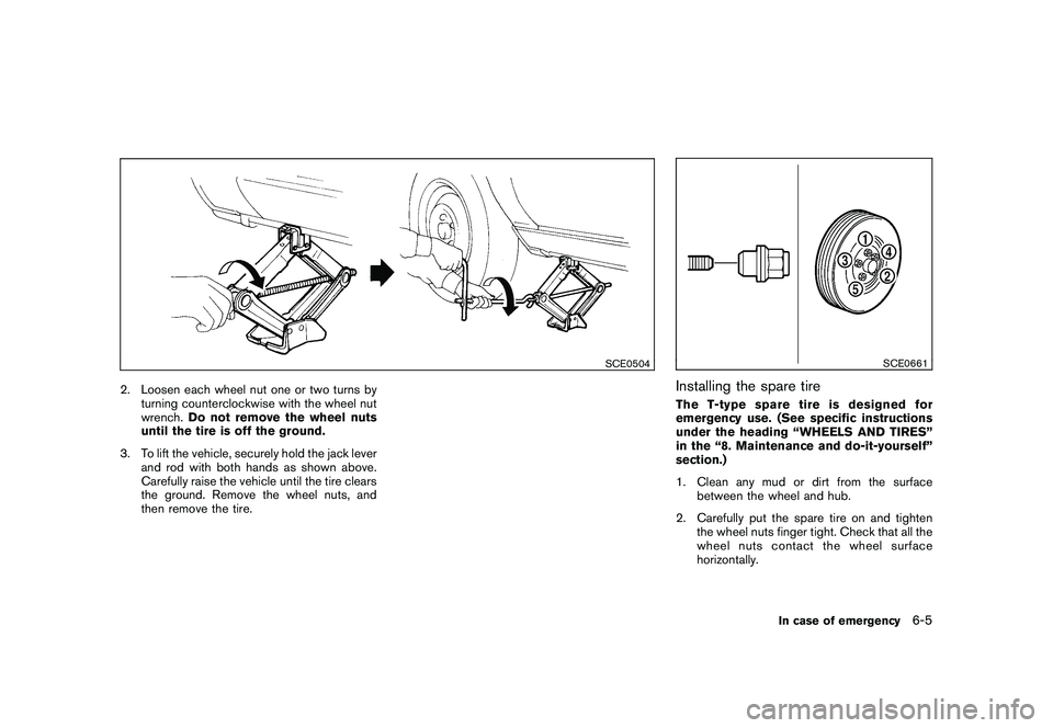
2. Loosen each wheel nut one or two turns byturning counterclockwise with the wheel nut
wrench. Do not remove the wheel nuts
until the tire is off the ground.
3. To lift the vehicle, securely hold the jack lever and rod with both hands as shown above.
Carefully raise the vehicle until the tire clears
the ground. Remove the wheel nuts, and
then remove the tire.
SCE0661
Installing the spare tireThe T-type spare tire is designed for
emergency use. (See specific instructions
under the heading “WHEELS AND TIRES”
in the “8. Maintenance and do-it-yourself”
section.)
1. Clean any mud or dirt from the surfacebetween the wheel and hub.
2. Carefully put the spare tire on and tighten the wheel nuts finger tight. Check that all the
wheel nuts contact the wheel surface
horizontally.
In case of emergency
6-5
Page 314 of 409
Black plate (314,1)
Model "Z34-D" EDITED: 2009/ 9/ 10
— when the sealant has passed itsexpiration date (shown on the
label attached to the bottle)
— when the cut or the puncture is approximately 0.16 in (4 mm)
(Type A)/0.25 in (6 mm) (Type B)
or longer
— when the tire sidewall is da- maged
— when the vehicle has been dri- ven with extremely low tire
pressure
— when the tire has come off the inside or the outside of the
wheel.
— when the tire wheel is damaged
— when two or more tires are flat
Stopping the vehicle1. Safely move the vehicle off the road and away from traffic.
2. Turn on the hazard warning flashers.
3. Park on a level surface and apply the parking brake.
4. Automatic Transmission models:
Move the selector lever to the P (Park)
position. Manual Transmission models:
Move the shift lever to the R (Reverse)
position.
5. Turn off the engine.
6. Raise the hood to warn other traffic and to signal professional road assistance person-
nel that you need assistance.
7. Have all passengers get out of the vehicle and stand in a safe place, away from traffic
and clear of the vehicle.
WARNING
Make sure the parking brake is securely
applied and the manual transmission is
shifted into R (Reverse) or the auto-
matic transmission into P (Park) .
.Never repair tires when the vehicle
is on a slope, ice or slippery areas.
This is hazardous.
. Never repair tires if oncoming traffic
is close to your vehicle. Wait for
professional road assistance.
SCE0846
Type A
6-8
In case of emergency
Page 315 of 409
Black plate (315,1)
Model "Z34-D" EDITED: 2009/ 9/ 10
SCE0866
Type B
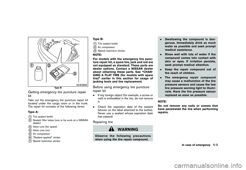
Getting emergency tire puncture repair
kitTake out the emergency tire puncture repair kit
located under the cargo room or in the trunk.
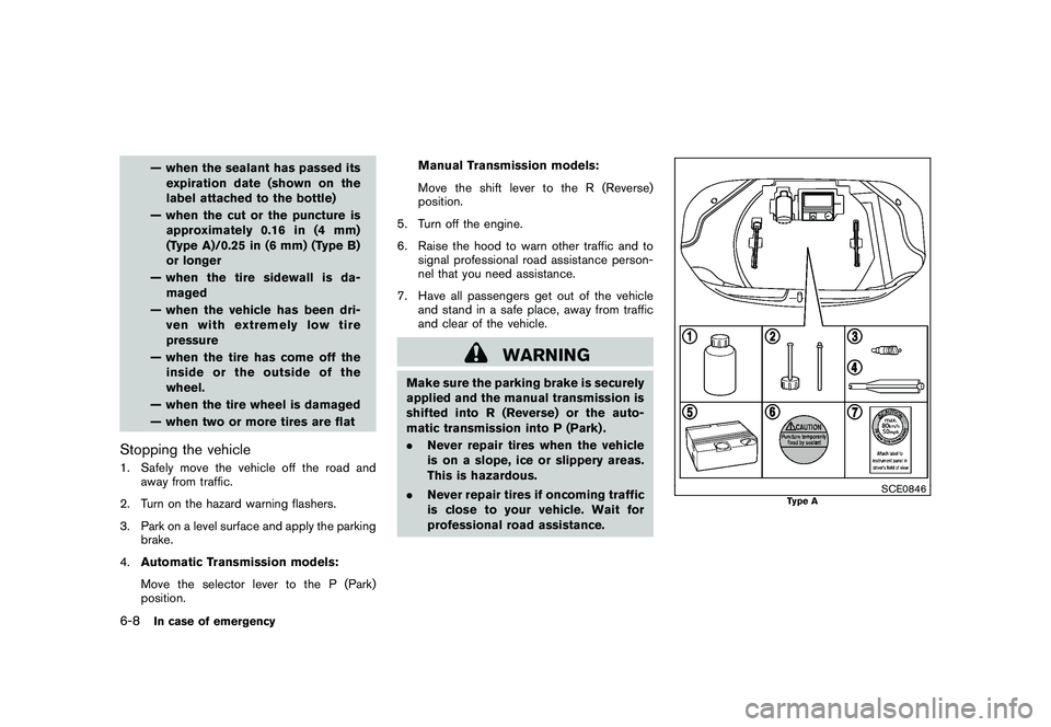
The repair kit consists of the following items:
Type A:*1
Tire sealant bottle
*2
Sealant filler tubes (one is for work at a NISSAN
dealer)
*3
Valve core (for spare)
*4
Valve core tool
*5
Air compressor
*6
“Sealant-applied” sticker
*7
Speed restriction sticker
Type B:*1
Tire sealant bottle
*2
Air compressor
*3
Speed restriction sticker
NOTE:
For models with the emergency tire punc-
ture repair kit, a spare tire, jack and rod are
not equipped as standard. These parts are
dealer options. Contact a NISSAN dealer
about obtaining these parts. See “CHAN-
GING A FLAT TIRE (for models with spare
tire)” earlier in this section for usage of
jacking tools and tire replacement.Before using emergency tire puncture
repair kit.If any foreign object (for example, a screw or
nail) is embedded in the tire, do not remove
it.
. Check the expiration date of the sealant
(shown on the label attached to the bottle) .
Never use a sealant whose expiration date
has passed.Repairing tire
WARNING
Observe the following precautions
when using the tire repair compound. .
Swallowing the compound is dan-
gerous. Immediately drink as much
water as possible and seek prompt
medical assistance.
. Rinse well with lots of water if the
compound comes into contact with
skin or eyes. If irritation persists,
seek prompt medical attention.
. Keep the repair compound out of
the reach of children.
. The emergency re pair compound
may cause a malfunction of the tire
pressure sensors and cause the low
tire pressure warning light to illumi-
nate. Have the tire pressure sensor
replaced as soon as possible.
NOTE:
Do not remove any nails or screws that
have penetrated the tire when performing
repairs.
In case of emergency
6-9
Page 316 of 409
Black plate (316,1)
Model "Z34-D" EDITED: 2009/ 9/ 10
SCE0775
Type A
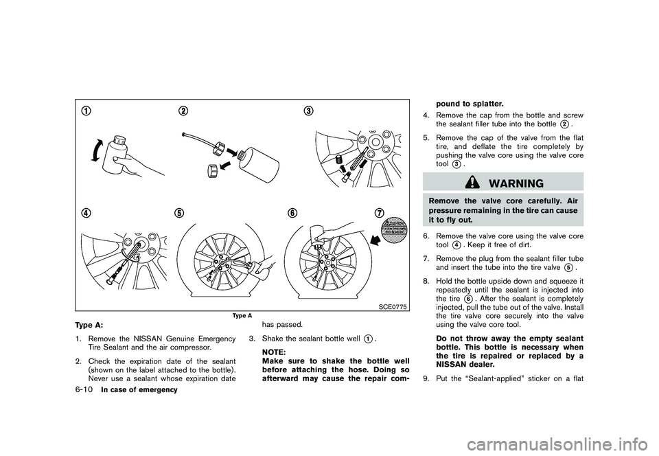
Type A:
1. Remove the NISSAN Genuine EmergencyTire Sealant and the air compressor.
2. Check the expiration date of the sealant (shown on the label attached to the bottle) .
Never use a sealant whose expiration date has passed.
3. Shake the sealant bottle well
*1.
NOTE:
Make sure to shake the bottle well
before attaching the hose. Doing so
afterward may cause the repair com- pound to splatter.
4. Remove the cap from the bottle and screw the sealant filler tube into the bottle
*2.
5. Remove the cap of the valve from the flat tire, and deflate the tire completely by
pushing the valve core using the valve core
tool
*3.
WARNING
Remove the valve core carefully. Air
pressure remaining in the tire can cause
it to fly out.
6. Remove the valve core using the valve core tool
*4. Keep it free of dirt.
7. Remove the plug from the sealant filler tube and insert the tube into the tire valve
*5.
8. Hold the bottle upside down and squeeze it repeatedly until the sealant is injected into
the tire
*6. After the sealant is completely
injected, pull the tube out of the valve. Install
the tire valve core securely into the valve
using the valve core tool.
Do not throw away the empty sealant
bottle. This bottle is necessary when
the tire is repaired or replaced by a
NISSAN dealer.
9. Put the “Sealant-applied” sticker on a flat
6-10
In case of emergency