2010 NISSAN 370Z COUPE power steering
[x] Cancel search: power steeringPage 19 of 409
Black plate (15,1)
Model "Z34-D" EDITED: 2009/ 9/ 10
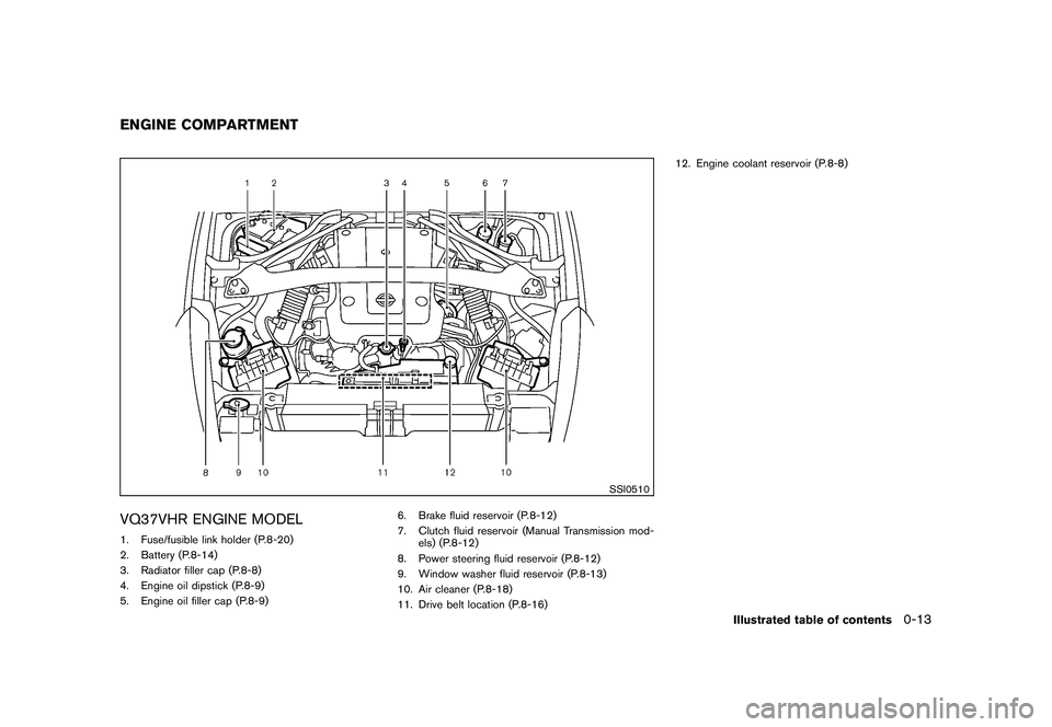
SSI0510
VQ37VHR ENGINE MODEL1. Fuse/fusible link holder (P.8-20)
2. Battery (P.8-14)
3. Radiator filler cap (P.8-8)
4. Engine oil dipstick (P.8-9)
5. Engine oil filler cap (P.8-9)6. Brake fluid reservoir (P.8-12)
7. Clutch fluid reservoir (Manual Transmission mod-
els) (P.8-12)
8. Power steering fluid reservoir (P.8-12)
9. Window washer fluid reservoir (P.8-13)
10. Air cleaner (P.8-18)
11. Drive belt location (P.8-16) 12. Engine coolant reservoir (P.8-8)ENGINE COMPARTMENT
Illustrated table of contents
0-13
Page 79 of 409
Black plate (77,1)
Model "Z34-D" EDITED: 2009/ 9/ 10
If this indicator appears, push the push-button
ignition switch while lightly turning the steering
wheel right and left.3. Key insertion indicatorThis indicator appears when the key needs to be
inserted into the key port. (For example, the
Intelligent Key battery is discharged.)
If this indicator appears, insert the key into the
key port in the correct direction. (See “PUSH-
BUTTON IGNITION SWITCH” in the “5. Start-
ing and driving” section.)4. Intelligent Key removal indicatorThis indicator appears when the driver’s door is
opened with the ignition switch in the OFF or
LOCK position and the Intelligent Key placed in
the key port. A key reminder chime also sounds.
If this indicator appears, remove the Intelligent
Key from the key port and take it with you when
leaving the vehicle.5. NO KEY warningThis warning appears in either of the following
conditions.
No Intelligent Key inside the vehicle:
The warning appears when the door is closed
with the Intelligent Key left outside the vehicle
and the ignition switch in the ACC or ON
position. Make sure that the Intelligent Key isinside the vehicle.
Unregistered Intelligent Key:
The warning appears when the ignition switch is
pushed from the LOCK position and the
Intelligent Key cannot be recognized by the
system. You cannot start the engine with an
unregistered key. Use the registered Intelligent
Key.
See “INTELLIGENT KEY SYSTEM” in the “3.
Pre-driving checks and adjustments” section for
more details.
6. SHIFT “P” warning (Automatic Trans-
mission models)This warning appears when the ignition switch is
pushed to stop the engine with the selector lever
in any position except the P (Park) position.
If this warning appears, move the selector lever
to the P (Park) position or push the ignition
switch to the ON position.
An inside warning chime will also sound. (See
“INTELLIGENT KEY SYSTEM” in the “3. Pre-
driving checks and adjustments” section.)7. “PUSH” warning (Automatic Trans-
mission models)This warning appears when the selector lever is
moved to the P (Park) position with the ignition
switch in the ACC position after the SHIFT “P”
warning appears.
To push the ignition switch to the OFF position,
perform the following procedure:
SHIFT “P” warning
?(Move the selector
lever to “P”) ?PUSH warning ?(Push the
ignition switch ?ignition switch position is
turned to ON) ?PUSH warning ?(Push the
ignition switch ?ignition switch position is
turned to OFF)
8. Intelligent Key battery discharge in-
dicatorThis indicator appears when the Intelligent Key
battery is running out of power.
If this indicator appears, replace the battery with
a new one. (See “INTELLIGENT KEY BATTERY
REPLACEMENT” in the “8. Maintenance and
do-it-yourself” section.)9. Engine start operation indicator
(Manual Transmission models)This indicator means that the engine will start by
pushing the ignition switch with the clutch pedal
depressed.
Instruments and controls
2-17
Page 113 of 409
Black plate (10,1)
3 Pre-driving checks and adjustments
Model "Z34-D" EDITED: 2009/ 9/ 10
Keys ............................................................... 3-2Intelligent Key ................................................ 3-2
Valet hand-off ................................................ 3-3
Doors .............................................................. 3-4
Locking with mechanical key ............................. 3-4
Opening and closing windows with the
mechanical key .............................................. 3-4
Locking with inside lock knob ........................... 3-5
Locking with power door lock switch .................. 3-5
Automatic door locks ...................................... 3-5
Intelligent Key system .......................................... 3-6
Intelligent Key operating range .......................... 3-8
Door locks/unlocks precaution .......................... 3-8
Intelligent Key operation ................................... 3-9
Battery saver system ..................................... 3-11
Warning signals ........................................... 3-11
Troubleshooting guide ................................... 3-12
Remote keyless entry system .............................. 3-13
How to use remote keyless entry system ........... 3-13
Hood ............................................................ 3-16
Rear hatch (Coupe models) ................................ 3-17
Rear hatch opener switch .............................. 3-17
Secondary rear hatch release .......................... 3-18
Trunk lid (Roadster models) ................................ 3-19
Trunk lid opener switch .................................. 3-19 Trunk release power cancel switch
................... 3-19
Interior trunk lid release ................................. 3-20
Secondary trunk lid release ............................ 3-21
Soft top (Roadster models) ................................ 3-21
Before operating the top ................................ 3-21
When operating the top ................................. 3-23
Opening the top .......................................... 3-25
Closing the top ............................................ 3-26
Opening the top using the Intelligent Key ........... 3-26
Troubleshooting guide ................................... 3-27
If the top does not open or close electrically . . .... 3-28
Care of the soft top and the vehicle body .......... 3-32
Front, side and rear unique parts
(NISMO models) .............................................. 3-32
Fuel-filler door ................................................. 3-34
Opening the fuel-filler door ............................. 3-34
Fuel-filler cap .............................................. 3-34
Tilt steering ..................................................... 3-35
Manual operation ......................................... 3-36
Sun visors ...................................................... 3-36
Mirrors ........................................................... 3-36
Inside mirror ................................................ 3-36
Outside mirrors ............................................ 3-38
Vanity mirror ................................................ 3-39
Page 275 of 409

Black plate (16,1)
5 Starting and driving
Model "Z34-D" EDITED: 2009/ 9/ 10
Precautions when starting and driving..................... 5-2
Exhaust gas (carbon monoxide) ......................... 5-2
Three-way catalyst .......................................... 5-2
Tire Pressure Monitoring System (TPMS) ............. 5-3
Avoiding collision and rollover ........................... 5-5
Off-road recovery ........................................... 5-6
Rapid air pressure loss .................................... 5-6
Drinking alcohol/drugs and driving ...................... 5-7
Push-button ignition switch .................................. 5-7
Operating range for engine start function ............. 5-8
Push-button ignition switch operation. ................. 5-8
Push-button ignition switch positions .................. 5-9
Intelligent Key battery discharge ...................... 5-10
Before starting the engine .................................. 5-10
Starting the engine ........................................... 5-11
Driving the vehicle ............................................ 5-12
Automatic transmission .................................. 5-12
Manual Transmission ..................................... 5-16
Parking brake .................................................. 5-20
Cruise control ................................................. 5-20
Precautions on cruise control .......................... 5-20
Cruise control operations ............................... 5-21 Break-in schedule
............................................ 5-22
Increasing fuel economy .................................... 5-23
Parking/parking on hills ...................................... 5-23
Power steering ................................................ 5-24
Brake system .................................................. 5-25
Braking precautions ...................................... 5-25
Parking brake break-in ................................... 5-25
Brake assist .................................................... 5-26
Brake assist ................................................ 5-26
Anti-lock Braking System (ABS) ...................... 5-26
Vehicle Dynamic Control (VDC) system ................. 5-27
Performance dampers (NISMO models) ................ 5-29
Cold weather driving ......................................... 5-30
Freeing a frozen door lock .............................. 5-30
Antifreeze ................................................... 5-30
Battery ...................................................... 5-30
Draining of coolant water ............................... 5-30
Tire equipment ............................................ 5-30
Special winter equipment ............................... 5-30
Driving on snow or ice .................................. 5-30
Engine block heater (if so equipped) ................. 5-31
Page 298 of 409
Black plate (298,1)
Model "Z34-D" EDITED: 2009/ 9/ 10
cannot be moved without depres-
sing the foot brake pedal.
1. Firmly apply the parking brake.
2. Automatic transmission models:
Move the selector lever to the P (Park)
position.
Manual transmission models:
Place the shift lever in the R (Reverse) gear.
When parking on an uphill grade, place the
shift lever in the 1st gear.
3. To help prevent the vehicle from rolling into the street when parked on a sloping drive
way, it is a good practice to turn the wheels
as illustrated.
.HEADED DOWNHILL WITH CURB:
*1
Turn the wheels into the curb and move the
vehicle forward until the curb side wheel
gently touches the curb.
.HEADED UPHILL WITH CURB:
*2
Turn the wheels away from the curb and
move the vehicle back until the curb side
wheel gently touches the curb.
.HEADED UPHILL OR DOWNHILL, NO
CURB:
*3
Turn the wheels toward the side of the road
so the vehicle will move away from the
center of the road if it moves.
4. Push the ignition switch to the OFF position.
WARNING
If the engine is not running or is turned
off while driving, the power assist for
the steering will not work. Steering will
be harder to operate.
The power assisted steering uses a hydraulic
pump, driven by the engine, to assist steering.
If the engine stops or the drive belt breaks, you
will still have control of the vehicle. However,
much greater steering effort is needed, espe-
cially in sharp turns and at low speeds.POWER STEERING
5-24
Starting and driving
Page 301 of 409

Black plate (301,1)
Model "Z34-D" EDITED: 2009/ 9/ 10
instrument panel. The brake system then oper-
ates normally, but without anti-lock assistance.
If the ABS warning light illuminates during the
self-test or while driving, have the vehicle
checked by a NISSAN dealer.Normal operationThe ABS operates at speeds above 3 to 6 MPH
(5 to 10 km/h) .
When the ABS senses that one or more wheels
are close to locking up, the actuator rapidly
applies and releases hydraulic pressure. This
action is similar to pumping the brakes very
quickly. You may feel a pulsation in the brake
pedal and hear a noise from under the hood or
feel a vibration from the actuator when it is
operating. This is normal and indicates that the
ABS is operating properly. However, the pulsa-
tion may indicate that road conditions are
hazardous and extra care is required while
driving.The Vehicle Dynamic Control (VDC) system
uses various sensors to monitor driver inputs
and vehicle motion. Under certain driving con-
ditions, the VDC system helps to perform the
following functions.
.
Controls brake pressure to reduce wheel
slip on one slipping drive wheel so power is
transferred to a non slipping drive wheel on
the same axle.
. Controls brake pressure and engine output
to reduce drive wheel slip based on vehicle
speed (traction control function) .
. Controls brake pressure at individual wheels
and engine output to help the driver maintain
control of the vehicle in the following
conditions:
— understeer (vehicle tends to not follow the steered path despite increased steering
input)
— oversteer (vehicle tends to spin due to certain road or driving conditions) .
The VDC system can help the driver to maintain
control of the vehicle, but it cannot prevent loss
of vehicle control in all driving situations.
When the VDC system operates, the
indicator in the instrument panel flashes so note
the following:
. The road may be slippery or the system may determine some action is required to help
keep the vehicle on the steered path.
. You may feel a pulsation in the brake pedal
and hear a noise or vibration from under the
hood. This is normal and indicates that the
VDC system is working properly.
. Adjust your speed and driving to the road
conditions.
See “Slip indicator light” in the “2. Instruments
and controls” section and “Vehicle Dynamic
Control (VDC) off indicator light” in the “2.
Instruments and controls” section.
If a malfunction occurs in the system, the
and
indicatorlightscomeoninthe
instrument panel. The VDC system automatically
turns off when these indicator lights are on.
The VDC OFF switch is used to turn off the VDC
system. The VDC off indicator illuminates to
indicate the VDC system is off. When the VDC
switch is used to turn off the system, the VDC
system still operates to prevent one drive wheel
from slipping by transferring power to a non
slipping drive wheel. The
indicator flashes
if this occurs. All other VDC functions are off and
the
indicator will not flash. The VDC
System is automatically reset to on when the
ignition switch is placed in the off position then
back to the on position.
The computer has a built-in diagnostic feature
VEHICLE DYNAMIC CONTROL (VDC)
SYSTEM
Starting and driving
5-27
Page 317 of 409
Black plate (317,1)
Model "Z34-D" EDITED: 2009/ 9/ 10
surface of the wheel
*7.
SCE0776
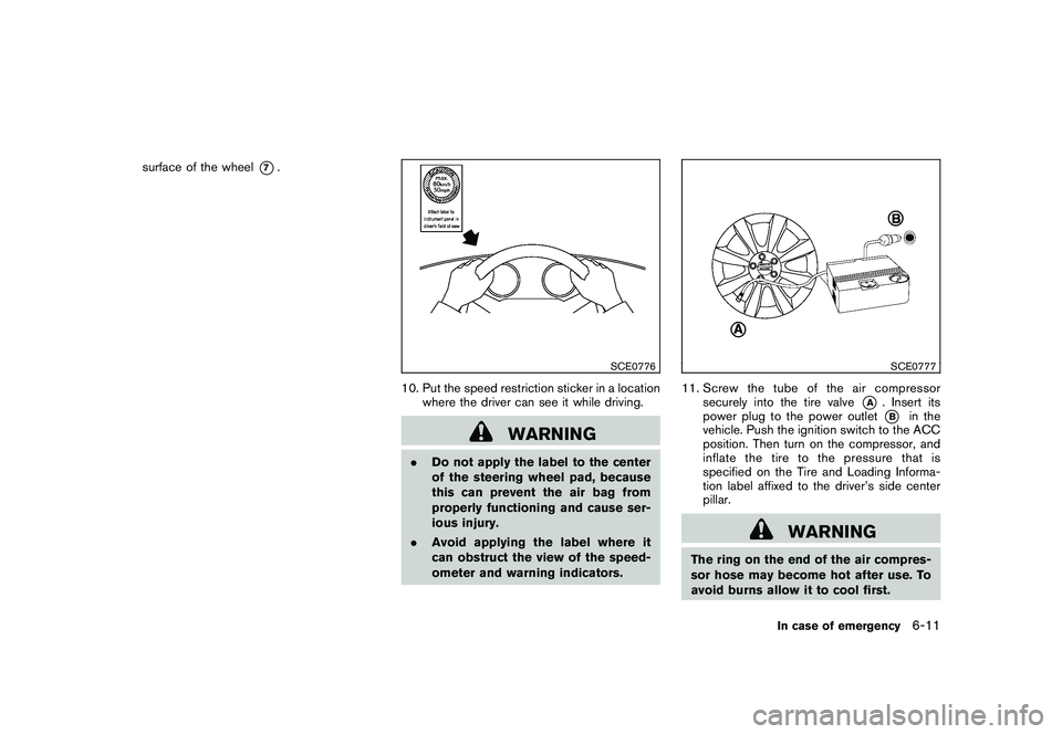
10. Put the speed restriction sticker in a locationwhere the driver can see it while driving.
WARNING
.Do not apply the label to the center
of the steering wheel pad, because
this can prevent the air bag from
properly functioning and cause ser-
ious injury.
. Avoid applying the label where it
can obstruct the view of the speed-
ometer and warning indicators.
SCE0777
11. Screw the tube of the air compressor
securely into the tire valve
*A
. Insert its
power plug to the power outlet*B
in the
vehicle. Push the ignition switch to the ACC
position. Then turn on the compressor, and
inflate the tire to the pressure that is
specified on the Tire and Loading Informa-
tion label affixed to the driver’s side center
pillar.
WARNING
The ring on the end of the air compres-
sor hose may become hot after use. To
avoid burns allow it to cool first.
In case of emergency
6-11
Page 322 of 409
Black plate (322,1)
Model "Z34-D" EDITED: 2009/ 9/ 10
protectors (for example, goggles or
industrial safetyspectacles) and
remove rings, metal bands, or any
other jewelry. Do not lean over the
battery when jump starting.
. Do not attempt to jump start a
frozen battery. It could explode
and cause serious injury.
. Your vehicle has an automatic en-
gine cooling fan. It could come on at
any time. Keep hands and other
objects away from it.
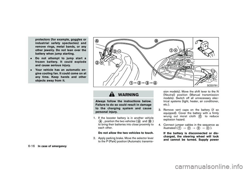
SCE0791
WARNING
Always follow the instructions below.
Failure to do so could result in damage
to the charging system and cause
personal injury.
1. If the booster battery is in another vehicle*A
, position the two vehicles (
*A
and
*B)
to bring their batteries into close proximity to
each other.
Do not allow the two vehicles to touch.
2. Apply parking brake. Move the selector lever to the P (Park) position (Automatic transmis- sion models) . Move the shift lever to the N
(Neutral) position (Manual transmission
models) . Switch off all unnecessary elec-
trical systems (light, heater, air conditioner,
etc.) .
3. Remove vent caps on the battery (if so equipped) . Cover the battery with a firmly
wrung out moist cloth
*C
to reduce
explosion hazard.
4. Connect jumper cables in the sequence as illustrated (
*1
?
*2
?
*3
?
*4).
If the battery is disconnected or dis-
charged, the steering wheel will lock
and cannot be turned. Supply power
6-16
In case of emergency