Page 493 of 658

5-86 Comfort controls
5
You can listen to commercially available audio equipment,
such as a portable audio system, from your vehicle’s speakers,
by connecting the audio equipment to the audio input connec-
tors, which are external input connectors (pin jacks).NOTE�
For information on using the video input connector (C),
refer to the separate owner’s manual for a Mitsubishi
Multi-Communication System.
To activate the external audio input mode1. Use a commercially available audio cable to connect the
audio equipment to the internal audio input connector.
2. Press and hold the CD button (D) for more than 2 seconds.
The display (E) will show “AUX” and then the external
audio input mode will be activated.
3. To deactivate the external audio input mode, press the
RADIO button (F) or the CD button (D) to switch to
another mode.
Auxiliary Audio connector (RCA)
A- Left audio input connector (white)
B- Right audio input connector (red)
Auxiliary Video connector (RCA)
A- Left audio input connector (white)
B- Right audio input connector (red)
C- Video input connector (yellow)
Auxiliary Audio connector
(RCA)
Auxiliary Video connector
(RCA) Ty p e 2
CAUTION
!�
Do not operate the connected audio equipment while
driving.
This could distract you and an accident might occur.
BK0103001US.book 86 ページ 2009年8月20日 木曜日 午前10時45分
Page 494 of 658

Comfort controls
5-87
5
NOTE�
The connected audio equipment cannot be operated with
the vehicle’s audio system.
�
Depending on the connected audio equipment, it may pro-
duce noise from the speakers.
�
Use the connected audio equipment’s own power source,
such as its battery.
Noise may be produced from the speakers if the connected
audio equipment is used while charging it using the 12 V
power outlet of the vehicle.
�
Do not activate the external audio input mode when no
audio equipment is connected.
Otherwise, noise may be produced from the speakers.
�
Connect audio equipment when the external audio input
mode is deactivated or lower the vehicle’s speaker volume
before connecting it.
Noise may be produced from the speakers if audio equip-
ment is connected after the external audio input mode is
activated.
�
For information on how to connect and operate the audio
equipment, refer to the owner’s manual for the equipment.
Steering wheel audio remote control switch
N00714800354
The remote control switch is located on the left side of the
steering wheel.
The switch can be operated when the ignition switch is in
either the “ON” or “ACC” position.Type 1
BK0103001US.book 87 ページ 2009年8月20日 木曜日 午前10時45分
Page 495 of 658
5-88 Comfort controls
5
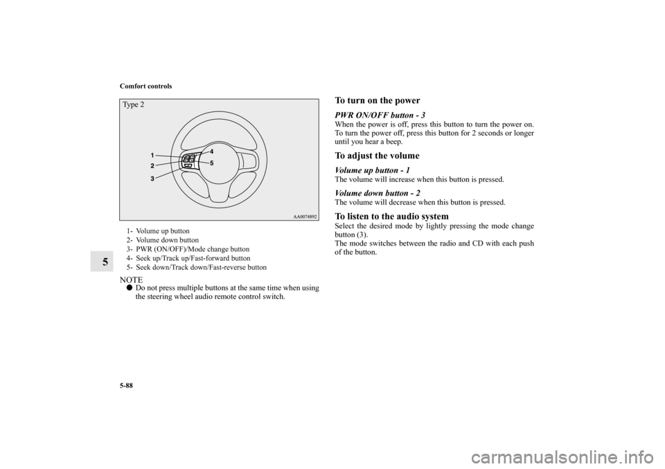
NOTE�
Do not press multiple buttons at the same time when using
the steering wheel audio remote control switch.
To turn on the powerPWR ON/OFF button - 3When the power is off, press this button to turn the power on.
To turn the power off, press this button for 2 seconds or longer
until you hear a beep.To adjust the volumeVolume up button - 1The volume will increase when this button is pressed.Volume down button - 2The volume will decrease when this button is pressed.To listen to the audio systemSelect the desired mode by lightly pressing the mode change
button (3).
The mode switches between the radio and CD with each push
of the button.
1- Volume up button
2- Volume down button
3- PWR (ON/OFF)/Mode change button
4- Seek up/Track up/Fast-forward button
5- Seek down/Track down/Fast-reverse buttonTy p e 2BK0103001US.book 88 ページ 2009年8月20日 木曜日 午前10時45分
Page 498 of 658
Comfort controls
5-91
5
ERROR HOTInside of audio system
is hot.Internal protection against high temperatures.Allow radio to cool by waiting about 30 min-
utes.
ERRORCommunication or
power supply errorCommunication error between external device
and audio equipment.
Power supply error of external device.Consult an authorized Mitsubishi Motors
dealer.Error display
Problem
Item
Repair
BK0103001US.book 91 ページ 2009年8月20日 木曜日 午前10時45分
Page 500 of 658

Comfort controls
5-93
5
NOTE�
Reception may not be possible in a place where the signal is interrupted by a tunnel, by the roof of a garage or other structure,
by woods, or by a tall building. At such times, the audio is muted. This behavior does not indicate a fault.
�
Reception conditions may vary according to the angle of the satellite used for the satellite radio service.
�
Reception may deteriorate if a luggage carrier is attached to the roof or snow collects on the antenna.
�
Satellite radio reception may not be possible in certain regions.
INVALID ↔ CHANNEL Channel is invalidNo program is currently being broadcast
on this channel; or reception is not possi-
ble with this channel.Consult SIRIUS Satellite Radio at
888-539-SIRIUS.
SAT ERRORMechanical fault or bad
connectionThere is a mechanical fault or a bad con-
nection.Take the vehicle to your authorized
Mitsubishi Motors dealer or a repair
facility of your choice.
OFF AIR OFF AIRThis channel is not broadcasting at the
present time; or satellite radio broadcast-
ing is suspended.Check the broadcast times with
SIRIUS Satellite Radio.
NOT ACTIVATED ID not registeredThe ID code in the receiver has not been
registered with SIRIUS Satellite Radio.Contact your authorized Mitsubishi
Motors dealer or a repair facility of
your choice.
READING Data reading in progress Reading of received data is in progress.Received data are being read. Please
wait.
UPDATINGChannel data updating
in progressSIRIUS Satellite Radio is presently updat-
ing the channel data.Wait until updating is complete.
SUB UPDATEDContract status updating
completeThe contract status has been updated. Press any audio key.
Error display
Problem
Description
Repair
BK0103001US.book 93 ページ 2009年8月20日 木曜日 午前10時45分
Page 502 of 658

Comfort controls
5-95
5
�
In the following circumstances, moisture can form on
discs and inside the audio system, preventing normal
operation.
When there is high humidity (for example, when it is
raining).
When the temperature suddenly rises, such as right after
the heater is turned on in cold weather.
In this case, wait until the moisture has had time to dry
out.
�
When the CD player is subjected to violent vibrations,
such as during off-road driving, the tracking may not
work.
�
When storing compact discs, always store them in their
separate cases. Never place compact discs in direct sun-
light, or in any place where the temperature or humidity is
high.
�
Never touch the flat surface of the disc where there isn’t a
label. This will damage the disc surface and could affect
the sound quality. When handling a compact disc, always
hold it by the outer edge and the center hole.
�
To clean a disc, use a soft, clean, dry cloth. Wipe directly
from the center hole toward the outer edge. Do not wipe in
a circle. Never use any chemicals such as benzine, paint
thinner, a disc spray cleaner, or an anti-static agent on the
disc.
�
Do not use a ball point pen, felt pen, pencil, etc. to write
on the label surface of the disc.
BK0103001US.book 95 ページ 2009年8月20日 木曜日 午前10時45分
Page 585 of 658

7-54 Vehicle care and maintenance
7
�
Some fuses may not be installed on your vehicle, depend-
ing on the vehicle model or specifications.
�
The table above shows the main equipment corresponding
to each fuse.
There are no 7.5 A, 25 A or 30 A spare fuses. If a fuse of one of
these capacities blows, replace it temporarily by borrowing one
of the fuses indicated below.
7.5 A: 10 A spare fuse
25 A: 20 A spare fuse
30 A: 30 A audio amplifier fuse
Replace the borrowed fuse with a fuse that has the correct
capacity as soon as possible.
17Headlight
(low/high beam) (right)20 A
*3
18Headlight
(low beam) (left)10 A
*4
19Headlight
(low beam) (right)10 A
*4
20
*1
ENG/POWER
10 A
*2
I/C SPRAY
21 Ignition coil 10 A
22
*1
ENG/POWER 20 A
Fuel line heater 25 A
22
*2
ENG/POWER 20 A
23 Fuel pump15 A
*1
20 A
*2
24 Starter
30 A
*5
25 — — —
26 Anti-lock braking system
40 A
*5
27 Anti-lock braking system
30 A
*5
28Air conditioning condenser fan
motor30 A
*5
29 Radiator fan motor
40 A
*5
No.
Symbol
Electrical system
Capacity
30 IOD IOD 30 A
31 Audio amplifier 30 A
32 Diesel 30 A
33 — Spare fuse 10 A
34 — Spare fuse 15 A
35 — Spare fuse 20 A
*1- Except for vehicles equipped with turbocharger
*2- Vehicles equipped with turbocharger
*3- For vehicles equipped with high intensity discharge head-
lights
*4- For vehicles without high intensity discharge headlights
*5- Fusible linkNo.
Symbol
Electrical system
Capacity
BK0103001US.book 54 ページ 2009年8月20日 木曜日 午前10時45分
Page 650 of 658
 1-8
ACD (Active center differential system) 3-127
Active stability control (ASC) 3-139
Air cleaner filter 7-14
Air conditioning
Automatic air conditioni")
Alphabetical index
1
A
Accessory (installation) 1-8
ACD (Active center differential system) 3-127
Active stability control (ASC) 3-139
Air cleaner filter 7-14
Air conditioning
Automatic air conditioning 5-6
,5-16
Important air conditioning operating tips 5-26
Air purifier 5-27
All-wheel drive system 3-125
Antenna
Roof antenna 5-97
,5-98
Anti-lock braking system 3-135
Warning light / display 3-136
,3-137
Arm rest 2-8
Ashtray 3-275
Assist grip 3-292
Audio
AM/FM electronically tuned radio with CD player 5-27
AM/FM electronically tuned radio with 6 CD autochanger 5-
55
Error codes 5-90
,5-92
Handling of compact discs 5-94
Steering wheel audio remote control switch 5-87
Automatic air conditioning 5-6
,5-16
Auxiliary audio connector (RCA) 5-85
Auxiliary video connector (RCA) 5-85
B
Back-up lights
Bulb capacity 7-58
replacement 7-84
Ball joint, steering linkage seals and drive shaft boots 7-44
Battery 7-23
Charging system warning light 3-216
Disconnection and connection 7-27
During cold weather 7-27
Specification 9-9
Bottle holder 3-289
Brake
Anti-lock braking system 3-135
Braking 4-6
Fluid 7-21
,9-10
Hose 7-44
Parking brake 3-74
Parking brake lever stroke 7-40
Pedal 3-131
Pedal free play 7-39
Power brakes 3-131
Service brake 3-131
Break-in recommendations 3-2
Bulb capacity 7-58
C
California Perchlorate Materials Requirements 1-10
Capacities 9-10
BK0103001US.book 1 ページ 2009年8月20日 木曜日 午前10時45分