Page 234 of 330

ROADSIDE ASSISTANCE
Getting roadside assistance
To fully assist you should you have a vehicle concern, Ford Motor
Company offers a complimentary roadside assistance program. This
program is separate from the New Vehicle Limited Warranty. The service
is available:
•24-hours, seven days a week
•for the coverage period listed on the Roadside Assistance Card
included in your Owner Guide portfolio.
Roadside assistance will cover:
•a flat tire change with a good spare (except vehicles that have been
supplied with a tire inflation kit)
•battery jump start
•lock-out assistance (key replacement cost is the customer’s
responsibility)
•fuel delivery – Independent Service Contractors, if not prohibited by
state, local or municipal law shall deliver up to 2.0 gallons (7.5L) of
gasoline or 5.0 gallons (18.9L) of diesel fuel to a disabled vehicle. Fuel
delivery service is limited to two no-charge occurrences within a
12-month period.
•winch out – available within 100 feet (30.5 meters) of a paved or
county maintained road, no recoveries.
•towing – Ford/Mercury/Lincoln eligible vehicle towed to an authorized
dealer within 35 miles (56 km) of the disablement location or to the
nearest authorized dealer. If a member requests to be towed to an
authorized dealer more than 35 miles (56 km) from the disablement
location, the member shall be responsible for any mileage costs in
excess of 35 miles (56 km).
Trailers shall be covered up to $200 if the disabled eligible vehicle
requires service at the nearest authorized dealer. If the trailer is disabled,
but the towing vehicle is operational, the trailer does not qualify for any
roadside services.
Canadian customers refer to your Customer Information Guide
for information on:
•coverage period
•exact fuel amounts
Roadside Emergencies
234
2010 Milan(mln)
Owners Guide, 3rd Printing
USA(fus)
Page 238 of 330
The fuses are coded as follows.
Fuse/Relay
LocationFuse Amp
RatingProtected Circuits
1 30A Driver smart window motor
2 15A Brake on/off switch, Center
high-mounted stop lamp
3 15A Not used (Spare)
4 30A Not used (Spare)
5 10A Keypad illumination, Brake shift
interlock
6 20A Turn signal lamps
7 10A Low beam headlamps (left)
8 10A Low beam headlamps (right)
9 15A Courtesy lamps
10 15A Backlighting, Puddle lamps
Roadside Emergencies
238
2010 Milan(mln)
Owners Guide, 3rd Printing
USA(fus)
Page 239 of 330

Fuse/Relay
LocationFuse Amp
RatingProtected Circuits
11 10A AWD module
12 7.5A Power outside mirrors
13 5A SYNC�module
14 10A Electronic finish panel (EFP)
radio and climate control buttons
module, Navigation display, Center
information display, GPS module
15 10A Climate control
16 15A Not used (Spare)
17 20A Door locks, Trunk release
18 20A Heated seats
19 25A Amplifier
20 15A On-board diagnostic connector
21 15A Fog lamps
22 15A Front sidemarker lamps, Park
lamps, License plate lamp
23 15A High beam headlamps
24 20A Horn
25 10A Demand lamps/power saver relay
26 10A Instrument cluster battery power
27 20A Ignition switch
28 5A Radio crank sense circuit
29 5A Instrument cluster ignition power
30 5A Not used (Spare)
31 10A Not used (Spare)
32 10A Restraint control module
33 10A Not used (Spare)
34 5A Not used (Spare)
35 10A Rear park assist, Blind spot
monitor system, Heated seats,
AWD, Rear video camera
Roadside Emergencies
239
2010 Milan(mln)
Owners Guide, 3rd Printing
USA(fus)
Page 241 of 330
If the battery has been disconnected and reconnected, refer to the
Batterysection of theMaintenance and Specificationschapter.
The high-current fuses are coded as follows.
Fuse/Relay
LocationFuse Amp
RatingProtected Circuits
1 50A* Electronic power assist steering
B+
2 50A* Electronic power assist steering
B+
3 40A* Powertrain control module (PCM)
(relay 57 power)
4 — Not used
5 30A* Starter motor (relay 55 power)
6 40A* Rear defrost (relay 53 power)
7 — Not used
8 40A* Anti-lock braking s ystem (ABS)
pump
9 20A* Wipers washer
10 30A* ABS valve
11 — Not used
Roadside Emergencies
241
2010 Milan(mln)
Owners Guide, 3rd Printing
USA(fus)
Page 246 of 330

Stopping and securing the vehicle
1. Park on a level surface, set the parking brake and activate the hazard
flashers.
2. Place the gearshift lever in P (Park) (automatic transmission) or R
(Reverse) (manual transmission) and turn the engine off.
Removing the spare tire and jack
1. Remove the carpeted load floor
panel located in the rear of the
vehicle and remove the lug wrench
and long bolt from the tool bag.
2. Remove the bolt securing the
spare tire using the lug wrench,
then lift and remove the spare tire
from the trunk.
3. Remove the jack retention bolt by
turning it counterclockwise and
remove the jack from the vehicle.
Tire change procedure
WARNING:To help prevent the vehicle from moving when you
change a tire, be sure the parking brake is set, then block (in
both directions) the wheel that is diagonally opposite (other side and
end of the vehicle) to the tire being changed.
WARNING:If the vehicle slips off the jack, you or someone else
could be seriously injured.
Roadside Emergencies
246
2010 Milan(mln)
Owners Guide, 3rd Printing
USA(fus)
Page 247 of 330
WARNING:Do not attempt to change a tire on the side of the
vehicle close to moving traffic. Pull far enough off the road to
avoid the danger of being hit when operating the jack or changing the
wheel.
Note:Passengers should not remain in the vehicle when the vehicle is
being jacked.
1. Block both the front and rear of
the wheel diagonally opposite the
flat tire. For example, if the left
front tire is flat, block the right rear
wheel.
2. Remove the center ornament (if
equipped) from the wheel. Loosen
each wheel lug nut one-half turn
counterclockwise but do not remove
them until the wheel is raised off
the ground.
Roadside Emergencies
247
2010 Milan(mln)
Owners Guide, 3rd Printing
USA(fus)
Page 248 of 330

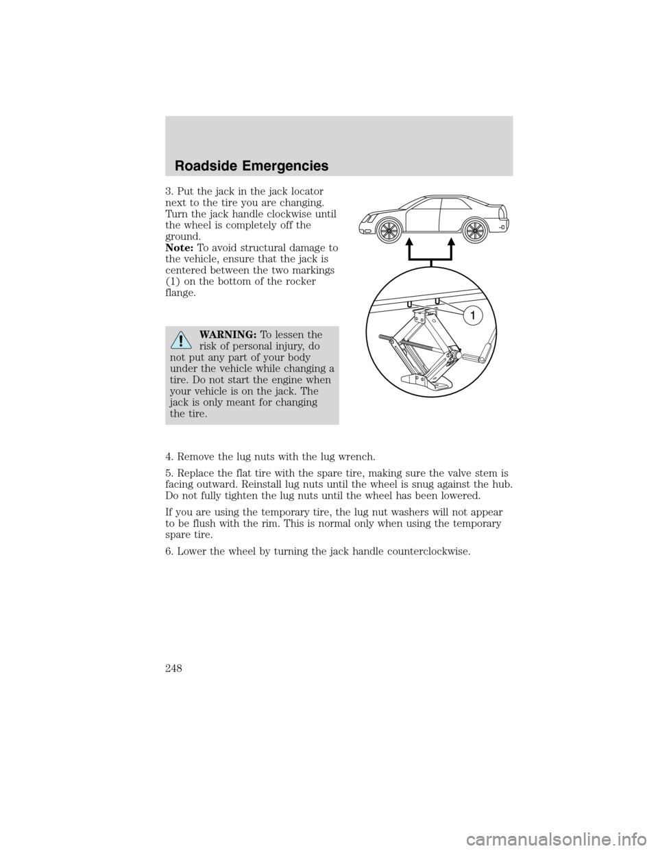
3. Put the jack in the jack locator
next to the tire you are changing.
Turn the jack handle clockwise until
the wheel is completely off the
ground.
Note:To avoid structural damage to
the vehicle, ensure that the jack is
centered between the two markings
(1) on the bottom of the rocker
flange.
WARNING:To lessen the
risk of personal injury, do
not put any part of your body
under the vehicle while changing a
tire. Do not start the engine when
your vehicle is on the jack. The
jack is only meant for changing
the tire.
4. Remove the lug nuts with the lug wrench.
5. Replace the flat tire with the spare tire, making sure the valve stem is
facing outward. Reinstall lug nuts until the wheel is snug against the hub.
Do not fully tighten the lug nuts until the wheel has been lowered.
If you are using the temporary tire, the lug nut washers will not appear
to be flush with the rim. This is normal only when using the temporary
spare tire.
6. Lower the wheel by turning the jack handle counterclockwise.
Roadside Emergencies
248
2010 Milan(mln)
Owners Guide, 3rd Printing
USA(fus)
Page 249 of 330

7. Remove the jack and fully tighten
the lug nuts in the order shown.
Refer toWheel lug nut torque
specificationslater in this chapter
for the proper lug nut torque
specification.
8. Unblock the wheels.
Stowing the wheel and jack
1. Fully collapse the jack and place it back in the storage area in the
trunk.
2. Replace the jack retention bolt to secure the jack.
3. Place the tire in the storage bin in the trunk.
4. Replace the cover plate and bolt.
•When storing a flat road tire, flip the cover plate over and use the long
bolt.
•When storing the temporary spare tire, replace the cover plate and
use the short bolt.
5. Secure the bolt using the lug wrench.
6. Insert the lug wrench and bolt in the tool bag and place over the jack.
7. Replace the carpeted load floor panel.
WHEEL LUG NUT TORQUE SPECIFICATIONS
Retighten the lug nuts to the specified torque at 500 miles (800 km)
after any wheel disturbance (tire rotation, changing a flat tire, wheel
removal, etc.).
Bolt size Wheel lug nut torque*
ft-lb N•m
M12 x 1.5 100 135
* Torque specifications are for nut and bolt threads free of dirt and
rust. Use only Ford recommended replacement fasteners.
1
4 3
2 5
Roadside Emergencies
249
2010 Milan(mln)
Owners Guide, 3rd Printing
USA(fus)