2010 MERCEDES-BENZ SLK55AMG flat tire
[x] Cancel search: flat tirePage 278 of 312
After attaining a tire inflation pressure of
at least 26 psi (1.8 bar):
X
Press 0 on electric air pump switch =.
The electric air pump is switched off.
X Detach the TIREFIT kit from the tire valve. G
Warning!
The air hose may still be hot. Exercise proper
caution to avoid burning yourself when
detaching the electric air pump.
! Remaining TIREFIT sealant could escape
from the filler hose after it has been
detached from the tire valve. TIREFIT
sealant may cause stains.
Therefore, cover the filler hose, e.g. by
inserting it into the plastic bag the TIREFIT
kit was packed in.
X Drive off immediately. G
Warning!
Do not exceed a vehicle speed of 50 mph
(80 km/h). A TIREFIT repair is not designed to
operate at higher speeds.
The sticker must be attached on the
instrument cluster where it will be easily seen
by the driver.
Vehicle handling characteristics of a TIREFIT
repaired tire may change. Adapt your driving
accordingly.
X After driving the vehicle for an initial
10 minutes, check the tire inflation
pressure using pressure gauge. G
Warning!
If tire inflation pressure has fallen below
20 psi (1.3 bar) do not continue to drive the
vehicle.
Park your vehicle safely away from the
roadway and contact the nearest authorized
Mercedes-Benz Center or Roadside
Assistance.
Have the damaged tire replaced. If the tire inflation pressure is at least 20 psi
(1.3 bar), inflate or deflate the tire to the
correct tire inflation pressure (see Tire and
Loading Information placard on the driver’s
door B-pillar):
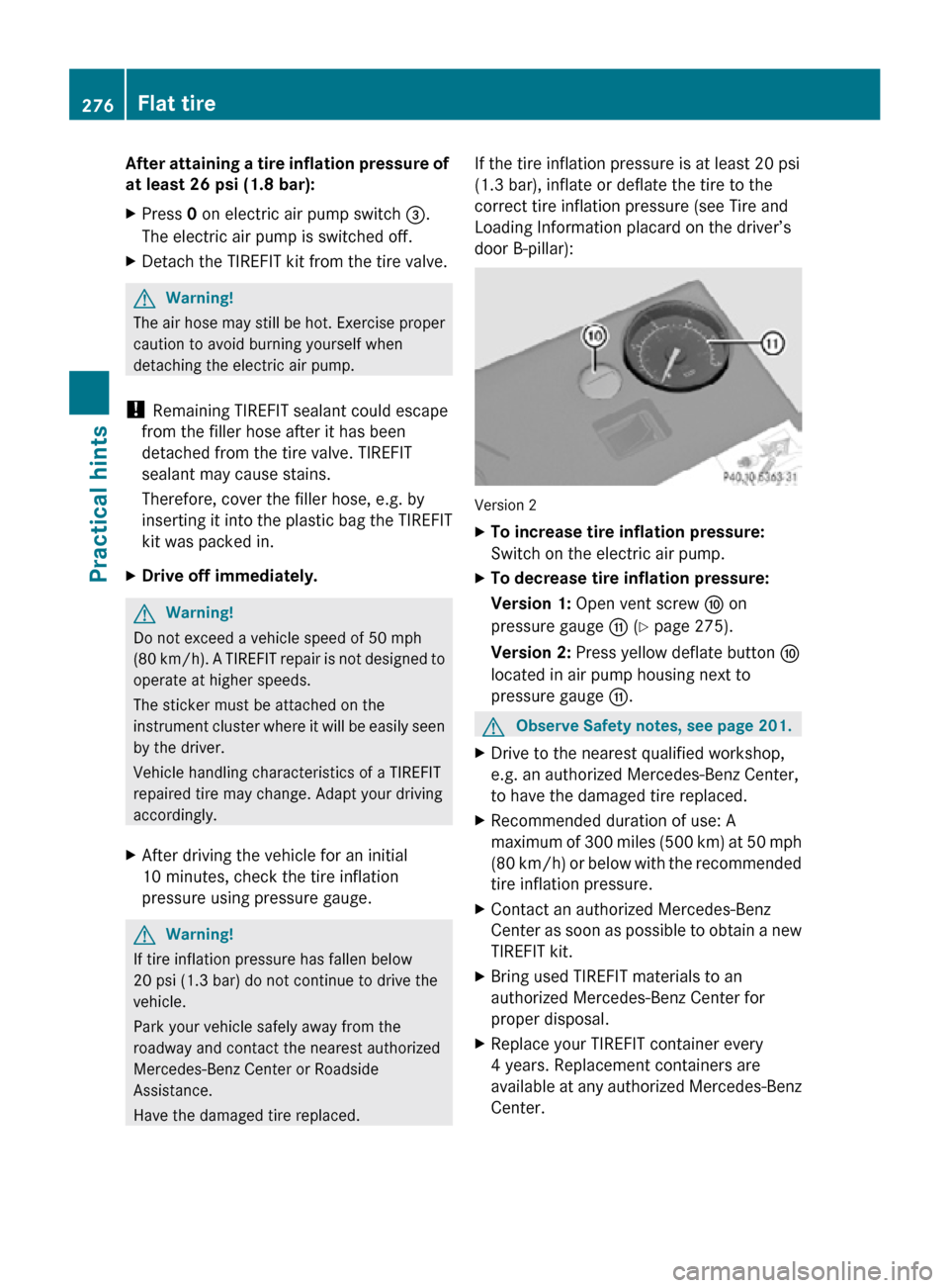
Version 2
X
To increase tire inflation pressure:
Switch on the electric air pump.
X To decrease tire inflation pressure:
Version 1: Open vent screw F on
pressure gauge G (Y page 275).
Version 2: Press yellow deflate button a
located in air pump housing next to
pressure gauge G. G
Observe Safety notes, see page 201.
X Drive to the nearest qualified workshop,
e.g. an authorized Mercedes-Benz Center,
to have the damaged tire replaced.
X Recommended duration of use: A
maximum of 300 miles (500 km) at 50 mph
(80 km/h) or below with the recommended
tire inflation pressure.
X Contact an authorized Mercedes-Benz
Center as soon as possible to obtain a new
TIREFIT kit.
X Bring used TIREFIT materials to an
authorized Mercedes-Benz Center for
proper disposal.
X Replace your TIREFIT container every
4 years. Replacement containers are
available at any authorized Mercedes-Benz
Center. 276
Flat tirePractical hints
171_AKB; 3; 60, en-US
d2ureepe,
Version: 2.11.8.1 2009-05-11T16:00:23+02:00 - Seite 276
Page 279 of 312
Mounting the spare wheel
Introduction X
Prepare the vehicle as described
(Y page 273).
X Take the following out of the vehicle:
R
spare wheel
R jack
R wheel wrench
R collapsible wheel chock
R wheel bolts for spare wheel
R alignment bolt
R electric air pump
For information on where to find the
respective items, see “Where will I find ...?”
(Y page 234) and ( Y page 235).
i Vehicles without spare wheel are not
factory-equipped
with the tools required for
a wheel change such as a jack or a wheel
wrench. Some tools required for a wheel
change are specific to your vehicle.
Contact an authorized Mercedes-Benz
Center to obtain the tools approved for
your vehicle. This section describes the
wheel change using the tools approved and
recommended for your vehicle.
Lifting the vehicle G
Warning!
When jacking up the vehicle, only use the jack
which has been specifically approved by
Mercedes-Benz for your vehicle.
The
jack is designed exclusively for jacking up
the vehicle at the jack take-up brackets built
into both sides of the vehicle. Make sure the
jack arm is fully seated in the jack take-up
bracket. The jack must always be vertical
when in use, especially on inclines or
declines.
The jack is intended only for lifting the vehicle
briefly for wheel changes. It is not suited for
performing maintenance work under the vehicle. To help avoid personal injury, use the
jack only to lift the vehicle during a wheel
change.
Never get beneath the vehicle while it is
supported by the jack. Keep hands and feet
away from the area under the lifted vehicle.
Always lower the vehicle onto sufficient
capacity
jackstands before working under the
vehicle.
Always engage the parking brake firmly and
block the wheels with wheel chocks or other
sizeable objects before raising the vehicle
with the jack. Do not disengage the parking
brake while the vehicle is raised.
Make sure that the ground on which the
vehicle is standing and where you place the
jack is solid, level and not slippery. If
necessary, use a large underlay. On slippery
surfaces, such as tiled floors, you should use
a non-slip underlay, for example a rubber mat.
Do not use wooden blocks or similar objects
to support the jack. Otherwise the jack may
not be able to achieve its load-bearing
capacity if it is not at its full height.
Never start the engine when the vehicle is
raised.
Also observe the notes on the jack.
X Prevent the vehicle from rolling away by
blocking
wheels with wheel chocks or other
sizeable objects.
When your vehicle is equipped with a wheel
chock, it is included with the vehicle tool kit
(Y page 234). For information on setting up
the collapsible wheel chock, see
(Y page 234).
When changing a wheel on a level surface:
X Place a wheel chock or other sizeable
object
in front of and another wheel chock
or other sizeable object behind the wheel
that is diagonally opposite to the wheel
being changed. Flat tire
277
Practical hints
171_AKB; 3; 60, en-US
d2ureepe, Version: 2.11.8.1 2009-05-11T16:00:23+02:00 - Seite 277 Z
Page 280 of 312
Always try lifting the vehicle using the jack on
a level surface. However, should
circumstances require you to do so on a hill:
X
Place wheel chocks or other sizeable
objects on the downhill side in front of both
wheels on the side opposite to the side on
which the wheel is to be changed. G
Warning!
Only jack up the vehicle on level ground or on
slight inclines/declines. Otherwise, the
vehicle could fall off the jack and injure you or
others. X
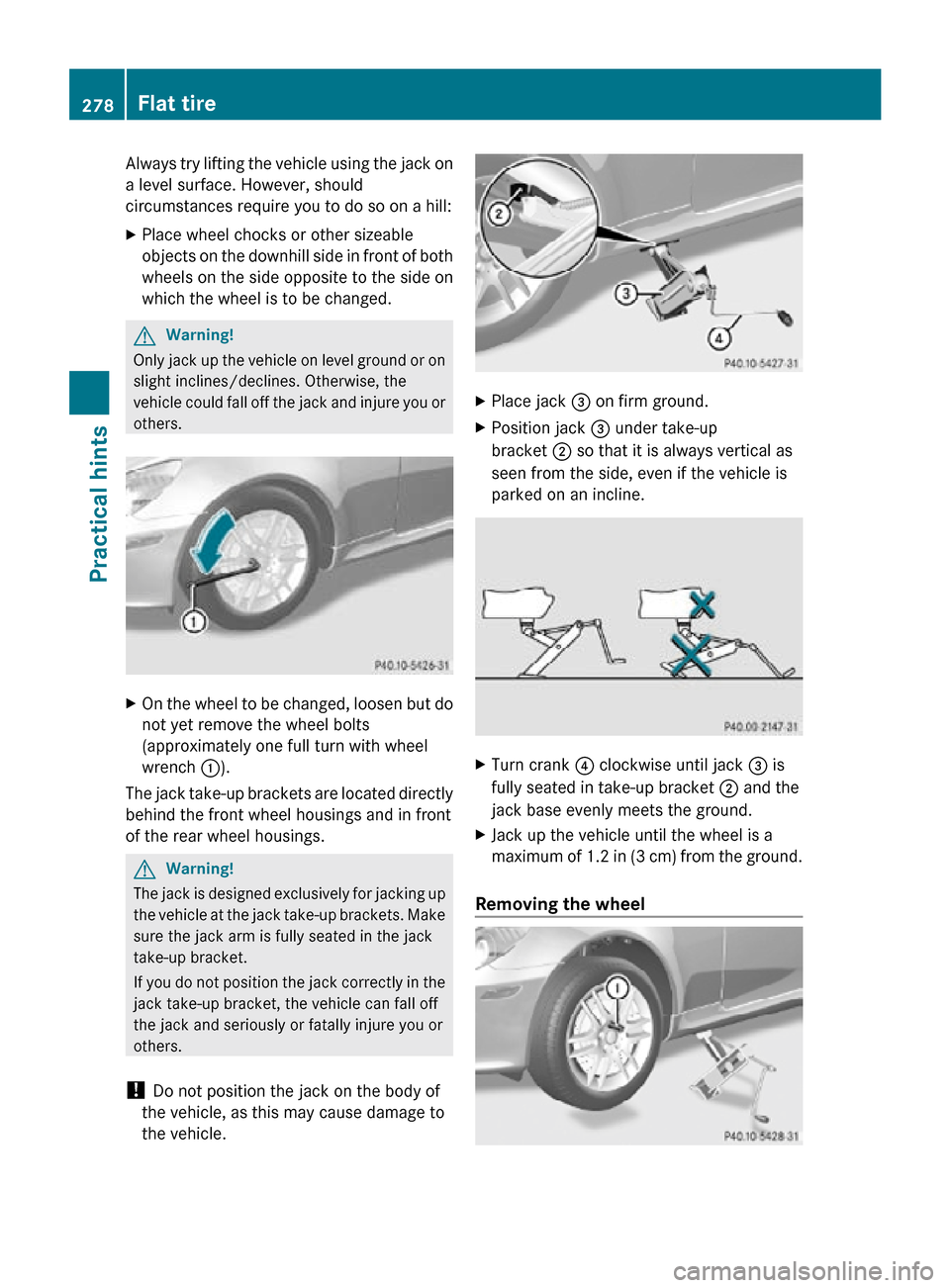
On the wheel to be changed, loosen but do
not yet remove the wheel bolts
(approximately one full turn with wheel
wrench :).
The jack take-up brackets are located directly
behind the front wheel housings and in front
of the rear wheel housings. G
Warning!
The jack is designed exclusively for jacking up
the vehicle at the jack take-up brackets. Make
sure the jack arm is fully seated in the jack
take-up bracket.
If you do not position the jack correctly in the
jack take-up bracket, the vehicle can fall off
the jack and seriously or fatally injure you or
others.
! Do not position the jack on the body of
the vehicle, as this may cause damage to
the vehicle. X
Place jack = on firm ground.
X Position jack = under take-up
bracket ; so that it is always vertical as
seen from the side, even if the vehicle is
parked on an incline. X
Turn crank ? clockwise until jack = is
fully seated in take-up bracket ; and the
jack base evenly meets the ground.
X Jack up the vehicle until the wheel is a
maximum of 1.2 in (3 cm) from the ground.
Removing the wheel 278
Flat tirePractical hints
171_AKB; 3; 60, en-US
d2ureepe,
Version: 2.11.8.1 2009-05-11T16:00:23+02:00 - Seite 278
Page 281 of 312
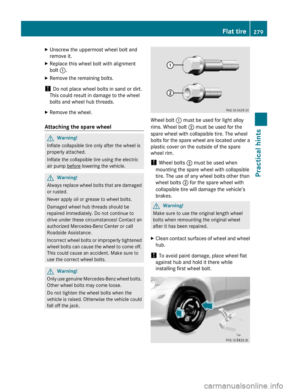
X
Unscrew the uppermost wheel bolt and
remove it.
X Replace this wheel bolt with alignment
bolt :.
X Remove the remaining bolts.
! Do not place wheel bolts in sand or dirt.
This could result in damage to the wheel
bolts and wheel hub threads.
X Remove the wheel.
Attaching the spare wheel G
Warning!
Inflate collapsible tire only after the wheel is
properly attached.
Inflate the collapsible tire using the electric
air pump before lowering the vehicle.
G
Warning!
Always replace wheel bolts that are damaged
or rusted.
Never apply oil or grease to wheel bolts.
Damaged wheel hub threads should be
repaired immediately. Do not continue to
drive under these circumstances! Contact an
authorized Mercedes-Benz Center or call
Roadside Assistance.
Incorrect wheel bolts or improperly tightened
wheel bolts can cause the wheel to come off.
This could cause an accident. Make sure to
use the correct wheel bolts. G
Warning!
Only use genuine Mercedes-Benz wheel bolts.
Other wheel bolts may come loose.
Do not tighten the wheel bolts when the
vehicle is raised. Otherwise the vehicle could
fall off the jack. Wheel bolt
: must be used for light alloy
rims. Wheel bolt ; must be used for the
spare wheel with collapsible tire. The wheel
bolts for the spare wheel are located under a
plastic cover on the outside of the spare
wheel rim.
! Wheel bolts ; must be used when
mounting the spare wheel with collapsible
tire. The use of any wheel bolts other than
wheel bolts ; for the spare wheel with
collapsible tire will damage the vehicle’s
brakes. G
Warning!
Make sure to use the original length wheel
bolts when remounting the original wheel
after it has been repaired.
X Clean contact surfaces of wheel and wheel
hub.
! To avoid paint damage, place wheel flat
against hub and hold it there while
installing first wheel bolt. Flat tire
279Practical hints
171_AKB; 3; 60, en-US
d2ureepe, Version: 2.11.8.1 2009-05-11T16:00:23+02:00 - Seite 279 Z
Page 282 of 312
X
Guide the spare wheel onto the alignment
bolt and push it on.
X Insert the wheel bolts and tighten them
slightly.
X Unscrew the alignment bolt.
X Install the last wheel bolt and tighten it
slightly.
X Inflate the collapsible tire ( Y page 280).
Inflating the collapsible tire G
Warning!
Inflate collapsible tire only after the wheel is
properly attached.
Inflate the collapsible tire using the electric
air pump before lowering the vehicle.
G
Warning!
Observe safety instructions on air pump label.
! Do not lower the vehicle before inflating
the collapsible tire. Otherwise the rim may
be damaged.
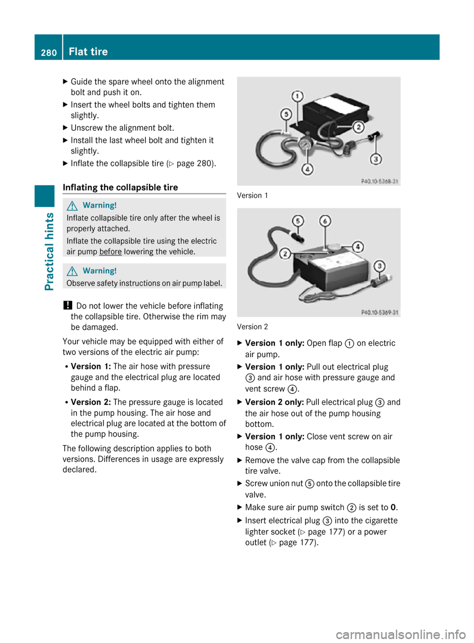
Your vehicle may be equipped with either of
two versions of the electric air pump:
R Version 1: The air hose with pressure
gauge and the electrical plug are located
behind a flap.
R Version 2: The pressure gauge is located
in the pump housing. The air hose and
electrical plug are located at the bottom of
the pump housing.
The following description applies to both
versions. Differences in usage are expressly
declared. Version 1
Version 2
X
Version 1 only: Open flap : on electric
air pump.
X Version 1 only: Pull out electrical plug
= and air hose with pressure gauge and
vent screw ?.
X Version 2 only: Pull electrical plug = and
the air hose out of the pump housing
bottom.
X Version 1 only: Close vent screw on air
hose ?.
X Remove the valve cap from the collapsible
tire valve.
X Screw union nut A onto the collapsible tire
valve.
X Make sure air pump switch ; is set to 0.
X Insert electrical plug = into the cigarette
lighter socket ( Y page 177) or a power
outlet (Y page 177). 280
Flat tirePractical hints
171_AKB; 3; 60, en-US
d2ureepe,
Version: 2.11.8.1 2009-05-11T16:00:23+02:00 - Seite 280
Page 283 of 312
X
Turn the SmartKey in the starter switch to
position 1.
X Press I on electric air pump switch ;.
The electric air pump switches on and
inflates the collapsible tire.
X Inflate the collapsible tire to the
recommended tire inflation pressure as
specified for your vehicle ( Y page 300).
This should take approximately 5 minutes. G
Warning!
The air hose and the union nut can become
hot during inflation. Exercise proper caution
to avoid burning yourself when using the
equipment.
! Do not operate the electric air pump
longer than 6 minutes without interruption.
Otherwise it may overheat.
You may operate the air pump again after
it has cooled off.
! Compare the recommended tire inflation
pressure for your vehicle with the tire
inflation pressure on the yellow label
located on the spare wheel rim.
If the tire inflation pressure on the yellow
label on the spare wheel rim differs from
the values given in this Operator’s Manual,
inflate the tire to the recommended tire
inflation pressure given on the yellow label
on the spare wheel rim.
X Press 0 on electric air pump switch ;.
X Turn the SmartKey in the starter switch to
position 0.
X Version 1 only: If the tire inflation pressure
is above the recommended tire inflation
pressure as specified for your vehicle
(Y page 300), decrease tire pressure using
the vent screw on air hose ?.
X Version 2 only: If the tire inflation pressure
is above the recommended tire inflation
pressure as specified for your vehicle
(Y page 300), decrease tire pressure using
deflate button B. G
Observe Safety notes, see page 201.
X Detach the electric air pump.
X Reinstall collapsible tire valve cap.
X Version 1 only: Store electrical plug =
and air hose ? behind flap :.
X Version 2 only: Store electrical plug =
and the air hose back into the pump
housing bottom.
X Place the electric air pump back in its
designated storage space.
X Lower the vehicle.
Lowering the vehicle G
Warning!
Inflate collapsible tire only after the wheel is
properly attached.
Inflate the collapsible tire using the electric
air pump before lowering the vehicle.
X Lower the vehicle by turning the crank
counterclockwise until the vehicle is
resting fully on its own weight.
X Remove the jack. X
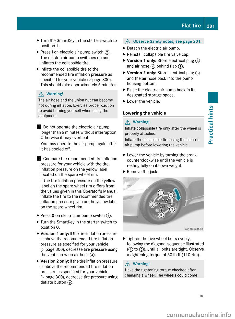
Tighten the five wheel bolts evenly,
following the diagonal sequence illustrated
(: to A), until all bolts are tight. Observe
a tightening torque of 80 lb-ft (110 Nm). G
Warning!
Have the tightening torque checked after
changing a wheel. The wheels could come Flat tire
281Practical hints
171_AKB; 3; 60, en-US
d2ureepe, Version: 2.11.8.1 2009-05-11T16:00:23+02:00 - Seite 281 Z
Page 299 of 312
!
This vehicle is not designed to carry items
on its roof. Roof rails and any roof-mounted
devices, unless expressly approved by
Mercedes-Benz for use on this vehicle
model, must not be used as they will
damage the vehicle and retractable
hardtop.
At time of printing, Mercedes-Benz does
not offer any roof racks or any other roof-
mounted devices for use on this vehicle.
! This vehicle is not designed to carry any
items on its trunk lid or accommodate any
type of trunk lid rack or device. Using such
devices may damage the vehicle and
retractable hardtop mechanism. Rims and tires
Notes
! Only
use tires which have been tested and
approved by Mercedes-Benz. Tires
approved by Mercedes-Benz are developed
to provide best possible performance in
conjunction with the driving safety systems
on your vehicle such as the ABS or the
ESP ®
. Tires specially developed for your
vehicle and tested and approved by
Mercedes-Benz can be identified by finding
the following on the tire’s sidewall:
R MO = Mercedes-Benz Original
equipment tires
Using tires other than those approved by
Mercedes-Benz may result in damage that
is not covered by the Mercedes-Benz
Limited Warranty.
! Using tires other than those approved by
Mercedes-Benz can have detrimental
effects, such as
R poor handling characteristics
R increased noise
R increased fuel consumption Moreover, tires and rims not approved by
Mercedes-Benz may, under load, exhibit
dimensional variations and different tire
deformation characteristics that could
cause them to come into contact with the
vehicle body or axle parts. Damage to the
tires or the vehicle may be the result.
i Further information on tires and rims is
available
at any authorized Mercedes-Benz
Center. The Tire and Loading Information
placard with the recommended tire
inflation pressures for cold tires is located
on the driver’s door B-pillar. Supplemental
tire inflation pressure information for
driving at high speeds or for vehicle loads
less than the maximum loaded vehicle
condition can be found on the tire inflation
pressure label. The tire inflation pressure
label is located on the inside of the fuel filler
flap. The tire inflation pressure should be
checked regularly and should only be
adjusted on cold tires. Follow tire
manufacturer’s maintenance
recommendation included with the vehicle.
For information on recommended tire
inflation pressure and supplemental tire
inflation pressure information for special
driving situations, see ( Y page 198).
i Please keep in mind that the vehicle must
be equipped
R with wheels of identical dimensions on
each axle (left and right)
R with tires of identical characteristics all
around, i.e. summer tires, winter tires, or
all-season tires etc.
i The following pages also list the approved
rim and tire sizes for equipping your vehicle
with winter tires. Winter tires are not
available as standard or optional factory
equipment, but can be purchased from an
authorized Mercedes-Benz Center.
Equipping your vehicle with winter tires
approved for your vehicle model may
require the purchase of rims of the Rims and tires
297
Technical data
171_AKB; 3; 60, en-US
d2ureepe, Version: 2.11.8.1 2009-05-11T16:00:23+02:00 - Seite 297 Z
Page 302 of 312
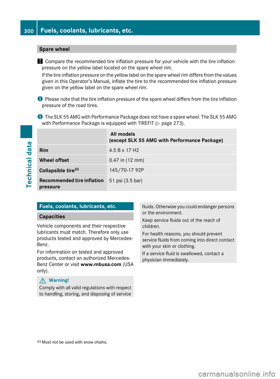
Spare wheel
! Compare the recommended tire inflation pressure for your vehicle with the tire inflation
pressure on the yellow label located on the spare wheel rim.
If
the tire inflation pressure on the yellow label on the spare wheel rim differs from the values
given in this Operator’s Manual, inflate the tire to the recommended tire inflation pressure
given on the yellow label on the spare wheel rim.
i Please note that the tire inflation pressure of the spare wheel differs from the tire inflation
pressure of the road tires.
i The SLK 55 AMG with Performance Package does not have a spare wheel. The SLK 55 AMG
with Performance Package is equipped with TIREFIT ( Y page 273). All models
(except SLK 55 AMG with Performance Package)
Rim
4.5 B x 17 H2
Wheel offset
0.47 in (12 mm)
Collapsible tire
33 145/70-17 92P
Recommended tire inflation
pressure
51 psi (3.5 bar)
Fuels, coolants, lubricants, etc.
Capacities
Vehicle components and their respective
lubricants must match. Therefore only use
products tested and approved by Mercedes-
Benz.
For information on tested and approved
products, contact an authorized Mercedes-
Benz Center or visit www.mbusa.com (USA
only). G
Warning!
Comply with all valid regulations with respect
to handling, storing, and disposing of service fluids. Otherwise you could endanger persons
or the environment.
Keep service fluids out of the reach of
children.
For health reasons, you should prevent
service
fluids from coming into direct contact
with your skin or clothing.
If a service fluid is swallowed, contact a
physician immediately.
33 Must not be used with snow chains. 300
Fuels, coolants, lubricants, etc.
Technical data
171_AKB; 3; 60, en-US
d2ureepe,
Version: 2.11.8.1 2009-05-11T16:00:23+02:00 - Seite 300