2010 MERCEDES-BENZ S65AMG run flat
[x] Cancel search: run flatPage 454 of 548
lower the trunk floor before closing the
trunk.
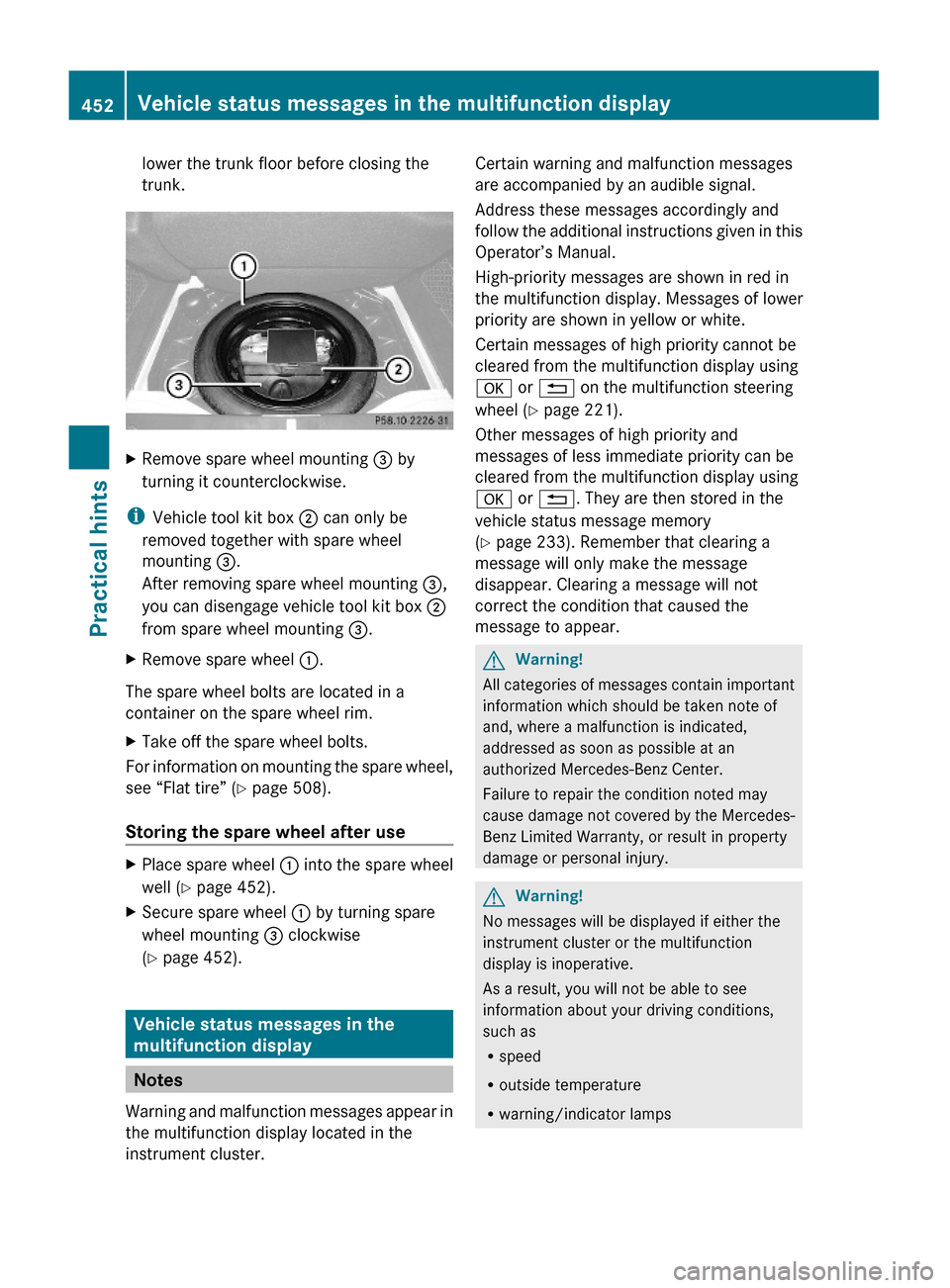
XRemove spare wheel mounting = by
turning it counterclockwise.
iVehicle tool kit box ; can only be
removed together with spare wheel
mounting =.
After removing spare wheel mounting =,
you can disengage vehicle tool kit box ;
from spare wheel mounting =.
XRemove spare wheel :.
The spare wheel bolts are located in a
container on the spare wheel rim.
XTake off the spare wheel bolts.
For information on mounting the spare wheel,
see “Flat tire” (Y page 508).
Storing the spare wheel after use
XPlace spare wheel : into the spare wheel
well (Y page 452).
XSecure spare wheel : by turning spare
wheel mounting = clockwise
(Y page 452).
Vehicle status messages in the
multifunction display
Notes
Warning and malfunction messages appear in
the multifunction display located in the
instrument cluster.
Certain warning and malfunction messages
are accompanied by an audible signal.
Address these messages accordingly and
follow the additional instructions given in this
Operator’s Manual.
High-priority messages are shown in red in
the multifunction display. Messages of lower
priority are shown in yellow or white.
Certain messages of high priority cannot be
cleared from the multifunction display using
a or % on the multifunction steering
wheel (Y page 221).
Other messages of high priority and
messages of less immediate priority can be
cleared from the multifunction display using
a or %. They are then stored in the
vehicle status message memory
(Y page 233). Remember that clearing a
message will only make the message
disappear. Clearing a message will not
correct the condition that caused the
message to appear.
GWarning!
All categories of messages contain important
information which should be taken note of
and, where a malfunction is indicated,
addressed as soon as possible at an
authorized Mercedes-Benz Center.
Failure to repair the condition noted may
cause damage not covered by the Mercedes-
Benz Limited Warranty, or result in property
damage or personal injury.
GWarning!
No messages will be displayed if either the
instrument cluster or the multifunction
display is inoperative.
As a result, you will not be able to see
information about your driving conditions,
such as
Rspeed
Routside temperature
Rwarning/indicator lamps
452Vehicle status messages in the multifunction displayPractical hints
221_AKB; 6; 20, en-USd2ugruen,Version: 2.11.8.12009-09-24T13:28:17+02:00 - Seite 452
Page 502 of 548
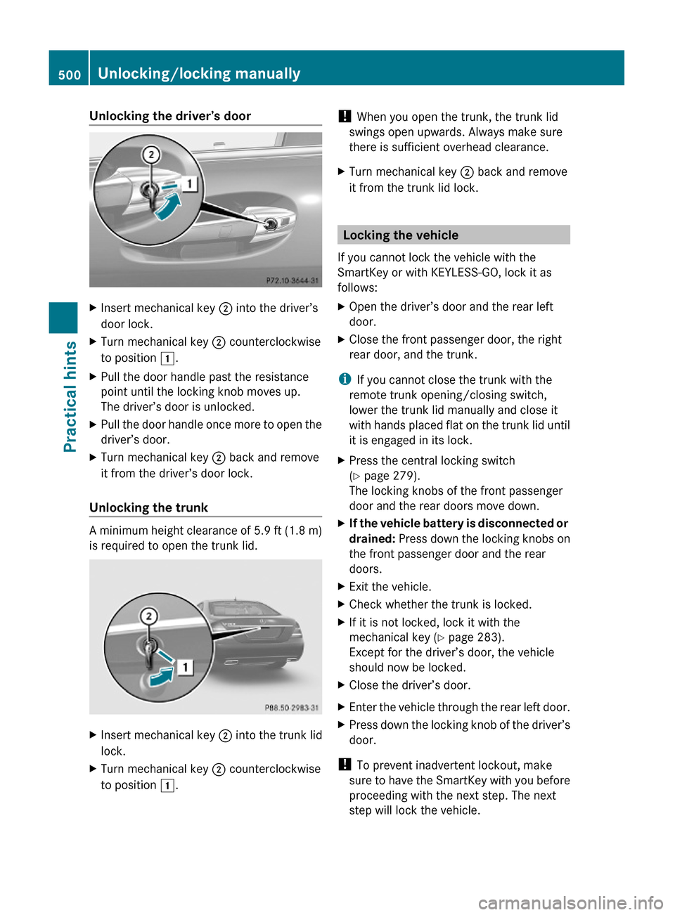
Unlocking the driver’s doorXInsert mechanical key ; into the driver’s
door lock.
XTurn mechanical key ; counterclockwise
to position 1.
XPull the door handle past the resistance
point until the locking knob moves up.
The driver’s door is unlocked.
XPull the door handle once more to open the
driver’s door.
XTurn mechanical key ; back and remove
it from the driver’s door lock.
Unlocking the trunk
A minimum height clearance of 5.9 ft (1.8 m)
is required to open the trunk lid.
XInsert mechanical key ; into the trunk lid
lock.
XTurn mechanical key ; counterclockwise
to position 1.
! When you open the trunk, the trunk lid
swings open upwards. Always make sure
there is sufficient overhead clearance.
XTurn mechanical key ; back and remove
it from the trunk lid lock.
Locking the vehicle
If you cannot lock the vehicle with the
SmartKey or with KEYLESS-GO, lock it as
follows:
XOpen the driver’s door and the rear left
door.
XClose the front passenger door, the right
rear door, and the trunk.
iIf you cannot close the trunk with the
remote trunk opening/closing switch,
lower the trunk lid manually and close it
with hands placed flat on the trunk lid until
it is engaged in its lock.
XPress the central locking switch
(Y page 279).
The locking knobs of the front passenger
door and the rear doors move down.
XIf the vehicle battery is disconnected or
drained: Press down the locking knobs on
the front passenger door and the rear
doors.
XExit the vehicle.XCheck whether the trunk is locked.XIf it is not locked, lock it with the
mechanical key (Y page 283).
Except for the driver’s door, the vehicle
should now be locked.
XClose the driver’s door.XEnter the vehicle through the rear left door.XPress down the locking knob of the driver’s
door.
! To prevent inadvertent lockout, make
sure to have the SmartKey with you before
proceeding with the next step. The next
step will lock the vehicle.
500Unlocking/locking manuallyPractical hints
221_AKB; 6; 20, en-USd2ugruen,Version: 2.11.8.12009-09-24T13:28:17+02:00 - Seite 500
Page 513 of 548
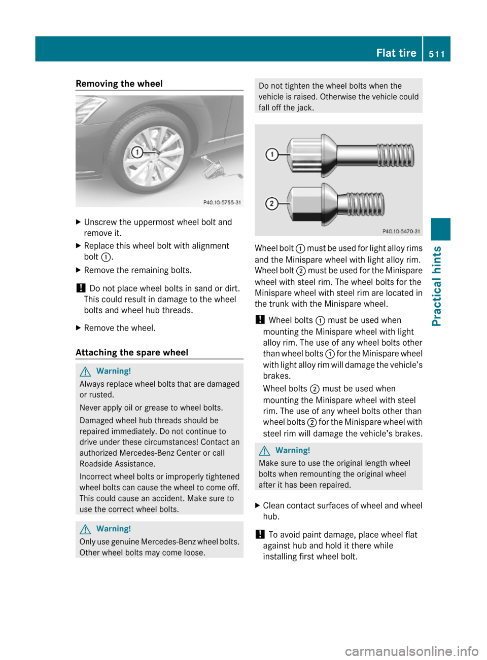
Removing the wheelXUnscrew the uppermost wheel bolt and
remove it.
XReplace this wheel bolt with alignment
bolt :.
XRemove the remaining bolts.
! Do not place wheel bolts in sand or dirt.
This could result in damage to the wheel
bolts and wheel hub threads.
XRemove the wheel.
Attaching the spare wheel
GWarning!
Always replace wheel bolts that are damaged
or rusted.
Never apply oil or grease to wheel bolts.
Damaged wheel hub threads should be
repaired immediately. Do not continue to
drive under these circumstances! Contact an
authorized Mercedes-Benz Center or call
Roadside Assistance.
Incorrect wheel bolts or improperly tightened
wheel bolts can cause the wheel to come off.
This could cause an accident. Make sure to
use the correct wheel bolts.
GWarning!
Only use genuine Mercedes-Benz wheel bolts.
Other wheel bolts may come loose.
Do not tighten the wheel bolts when the
vehicle is raised. Otherwise the vehicle could
fall off the jack.
Wheel bolt : must be used for light alloy rims
and the Minispare wheel with light alloy rim.
Wheel bolt ; must be used for the Minispare
wheel with steel rim. The wheel bolts for the
Minispare wheel with steel rim are located in
the trunk with the Minispare wheel.
! Wheel bolts : must be used when
mounting the Minispare wheel with light
alloy rim. The use of any wheel bolts other
than wheel bolts : for the Minispare wheel
with light alloy rim will damage the vehicle’s
brakes.
Wheel bolts ; must be used when
mounting the Minispare wheel with steel
rim. The use of any wheel bolts other than
wheel bolts ; for the Minispare wheel with
steel rim will damage the vehicle’s brakes.
GWarning!
Make sure to use the original length wheel
bolts when remounting the original wheel
after it has been repaired.
XClean contact surfaces of wheel and wheel
hub.
! To avoid paint damage, place wheel flat
against hub and hold it there while
installing first wheel bolt.
Flat tire511Practical hints221_AKB; 6; 20, en-USd2ugruen,Version: 2.11.8.12009-09-24T13:28:17+02:00 - Seite 511Z
Page 518 of 548
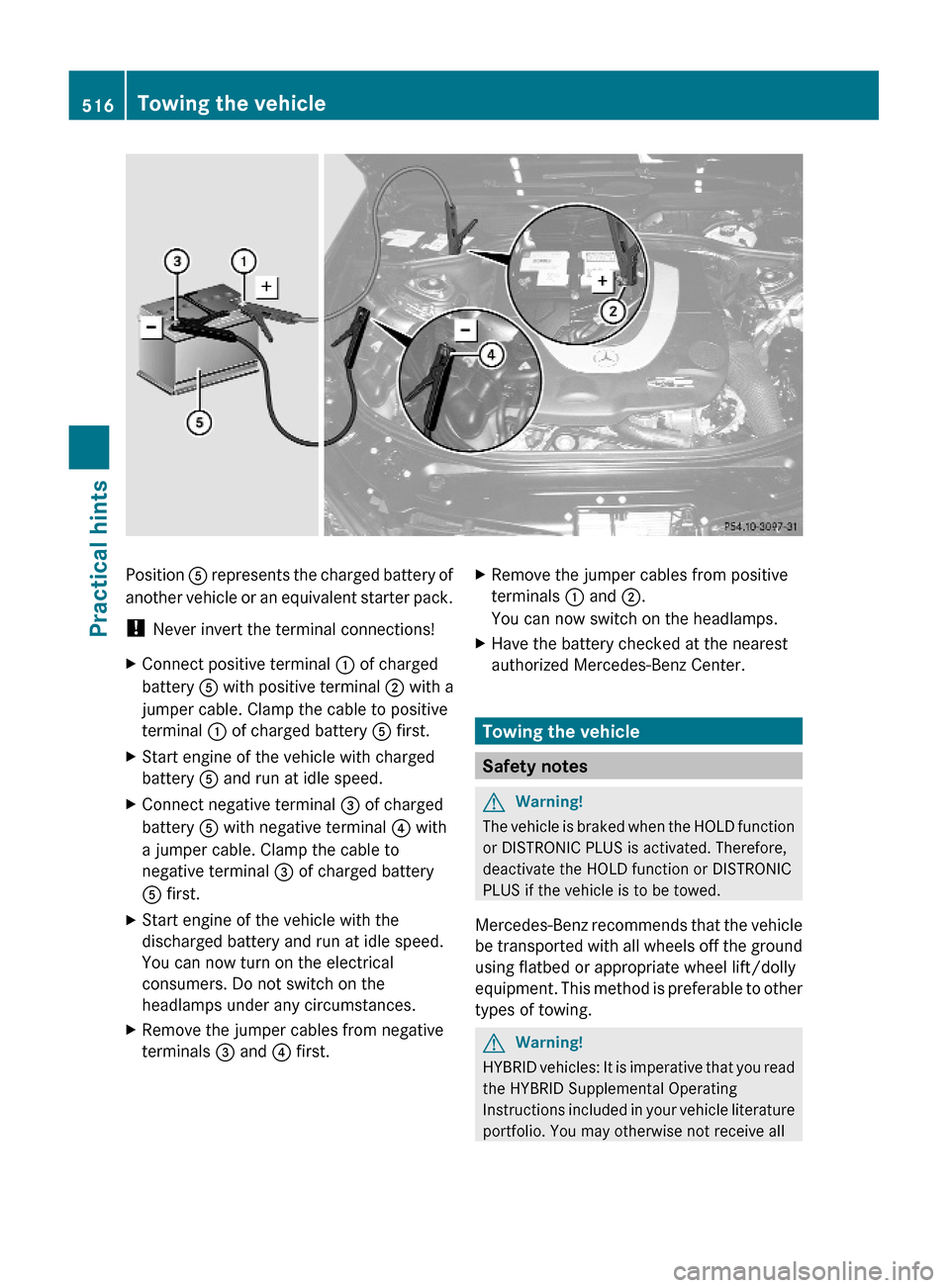
Position A represents the charged battery of
another vehicle or an equivalent starter pack.
! Never invert the terminal connections!
XConnect positive terminal : of charged
battery A with positive terminal ; with a
jumper cable. Clamp the cable to positive
terminal : of charged battery A first.
XStart engine of the vehicle with charged
battery A and run at idle speed.
XConnect negative terminal = of charged
battery A with negative terminal ? with
a jumper cable. Clamp the cable to
negative terminal = of charged battery
A first.
XStart engine of the vehicle with the
discharged battery and run at idle speed.
You can now turn on the electrical
consumers. Do not switch on the
headlamps under any circumstances.
XRemove the jumper cables from negative
terminals = and ? first.
XRemove the jumper cables from positive
terminals : and ;.
You can now switch on the headlamps.
XHave the battery checked at the nearest
authorized Mercedes-Benz Center.
Towing the vehicle
Safety notes
GWarning!
The vehicle is braked when the HOLD function
or DISTRONIC PLUS is activated. Therefore,
deactivate the HOLD function or DISTRONIC
PLUS if the vehicle is to be towed.
Mercedes-Benz recommends that the vehicle
be transported with all wheels off the ground
using flatbed or appropriate wheel lift/dolly
equipment. This method is preferable to other
types of towing.
GWarning!
HYBRID vehicles: It is imperative that you read
the HYBRID Supplemental Operating
Instructions included in your vehicle literature
portfolio. You may otherwise not receive all
516Towing the vehiclePractical hints
221_AKB; 6; 20, en-USd2ugruen,Version: 2.11.8.12009-09-24T13:28:17+02:00 - Seite 516
Page 534 of 548
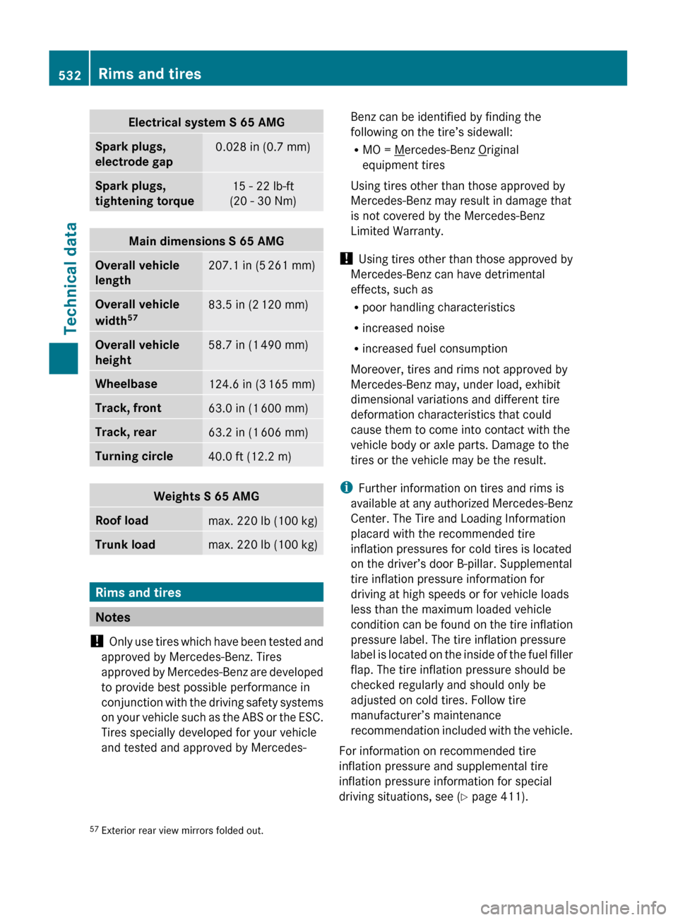
Electrical system S 65 AMGSpark plugs,
electrode gap0.028 in (0.7 mm)Spark plugs,
tightening torque15 - 22 lb-ft
(20 - 30 Nm)Main dimensions S 65 AMGOverall vehicle
length207.1 in (5 261 mm)Overall vehicle
width 5783.5 in (2
120 mm)Overall vehicle
height58.7 in (1 490 mm)Wheelbase124.6 in (3 165 mm)Track, front63.0 in (1 600 mm)Track, rear63.2 in (1 606 mm)Turning circle40.0 ft (12.2 m)Weights S 65 AMGRoof loadmax. 220 lb (100 kg)Trunk loadmax. 220 lb (100 kg)
Rims and tires
Notes
! Only use tires which have been tested and
approved by Mercedes-Benz. Tires
approved by Mercedes-Benz are developed
to provide best possible performance in
conjunction with the driving safety systems
on your vehicle such as the ABS or the ESC.
Tires specially developed for your vehicle
and tested and approved by Mercedes-
Benz can be identified by finding the
following on the tire’s sidewall:
R MO =
Mercedes-Benz Original
equipment tires
Using tires other than those approved by
Mercedes-Benz may result in damage that
is not covered by the Mercedes-Benz
Limited Warranty.
! Using tires other than those approved by
Mercedes-Benz can have detrimental
effects, such as
R poor handling characteristics
R increased noise
R increased fuel consumption
Moreover, tires and rims not approved by
Mercedes-Benz may, under load, exhibit
dimensional variations and different tire
deformation characteristics that could
cause them to come into contact with the
vehicle body or axle parts. Damage to the
tires or the vehicle may be the result.
i Further information on tires and rims is
available at any authorized Mercedes-Benz
Center. The Tire and Loading Information
placard with the recommended tire
inflation pressures for cold tires is located
on the driver’s door B-pillar. Supplemental
tire inflation pressure information for
driving at high speeds or for vehicle loads
less than the maximum loaded vehicle
condition can be found on the tire inflation
pressure label. The tire inflation pressure
label is located on the inside of the fuel filler
flap. The tire inflation pressure should be
checked regularly and should only be
adjusted on cold tires. Follow tire
manufacturer’s maintenance
recommendation included with the vehicle.
For information on recommended tire
inflation pressure and supplemental tire
inflation pressure information for special
driving situations, see ( Y page 411).
57
Exterior rear view mirrors folded out.532Rims and tiresTechnical data
221_AKB; 6; 20, en-USd2ugruen,Version: 2.11.8.12009-09-24T13:28:17+02:00 - Seite 532