2010 MERCEDES-BENZ S600 brakes
[x] Cancel search: brakesPage 341 of 548
Rthe radar sensors are switched off
Ryou pull the DISTRONIC PLUS lever in
direction of arrow ? (Y page 335) for
driving off and the front passenger or a rear
passenger door is open
The marker for the set speed on the
speedometer dial go out, an acoustic signal
sounds, and the message DISTRONIC PLUS
Off appears in the multifunction display for
approximately 5 seconds.
GWarning!
The DISTRONIC PLUS switches off and
releases the brakes when the vehicle
decelerates below the minimum speed of
20 mph (30 km/h) by operation of the system
unless the DISTRONIC PLUS detects a vehicle
directly ahead of you. At that time the driver
must apply the brakes in order to reduce
vehicle speed further or bring it to a stop.
Depressing the accelerator pedal does not
deactivate the DISTRONIC PLUS. After a brief
acceleration (e.g. for passing), the
DISTRONIC PLUS will resume the last set
speed.
Setting the following distance in
DISTRONIC PLUS
You can set the specified following distance
for the DISTRONIC PLUS by varying the time
setting between 1.0 and 2.0 seconds. Using
this time setting and the current speed of
your vehicle, the DISTRONIC PLUS calculates
and sets the required following distance to
the preceding vehicle.
The set distance will be shown in the
multifunction display.
GWarning!
It is up to the driver to exercise discretion to
select the appropriate setting given road
conditions, traffic, driver’s preferred driving
style and applicable laws and driving
recommendations for safe following distance.
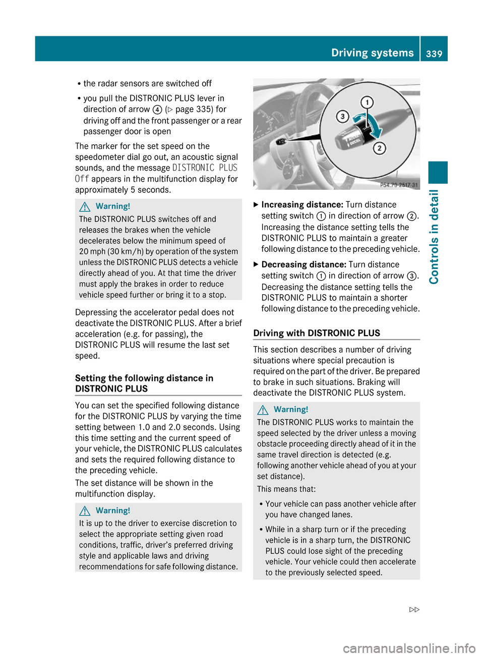
XIncreasing distance: Turn distance
setting switch : in direction of arrow ;.
Increasing the distance setting tells the
DISTRONIC PLUS to maintain a greater
following distance to the preceding vehicle.
XDecreasing distance: Turn distance
setting switch : in direction of arrow =.
Decreasing the distance setting tells the
DISTRONIC PLUS to maintain a shorter
following distance to the preceding vehicle.
Driving with DISTRONIC PLUS
This section describes a number of driving
situations where special precaution is
required on the part of the driver. Be prepared
to brake in such situations. Braking will
deactivate the DISTRONIC PLUS system.
GWarning!
The DISTRONIC PLUS works to maintain the
speed selected by the driver unless a moving
obstacle proceeding directly ahead of it in the
same travel direction is detected (e.g.
following another vehicle ahead of you at your
set distance).
This means that:
RYour vehicle can pass another vehicle after
you have changed lanes.
RWhile in a sharp turn or if the preceding
vehicle is in a sharp turn, the DISTRONIC
PLUS could lose sight of the preceding
vehicle. Your vehicle could then accelerate
to the previously selected speed.
Driving systems339Controls in detail221_AKB; 6; 20, en-USd2ugruen,Version: 2.11.8.12009-09-24T13:28:17+02:00 - Seite 339Z
Page 344 of 548
HOLD function
The HOLD function can assist you
Rwhen driving off, especially on steep slopes
Rwhen maneuvering on steep slopes
Rwhen waiting in traffic
The vehicle is kept stationary without the
driver having to depress the brake pedal.
Upon depressing the accelerator pedal, the
braking effect is canceled and the HOLD
function is deactivated.
GWarning!
HYBRID vehicles: It is imperative that you read
the HYBRID Supplemental Operating
Instructions included in your vehicle literature
portfolio. You may otherwise not receive all
necessary safety information and warning for
the operation of your vehicle.
Activation conditions
You can activate the HOLD function when
Rthe vehicle is stationary
Rthe engine is running
Ryour seat belt is fastened or the driver’s
door is closed
Rthe electronic parking brake is released
Rthe hood is closed
Rthe automatic transmission is in neutral
position N, drive position D, or reverse gear
R
When the automatic transmission is in
reverse gear R, the trunk lid must be
closed.
Rthe DISTRONIC PLUS is deactivated
(Y page 338).
Activating HOLD XMake sure the activation conditions are
met.
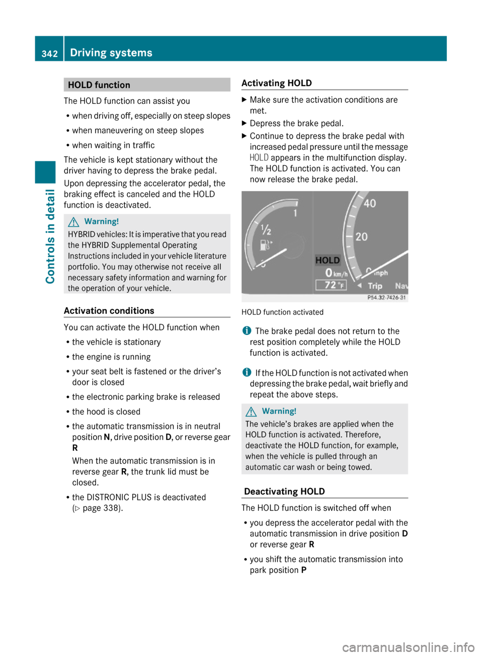
XDepress the brake pedal.XContinue to depress the brake pedal with
increased pedal pressure until the message
HOLD appears in the multifunction display.
The HOLD function is activated. You can
now release the brake pedal.
HOLD function activated
iThe brake pedal does not return to the
rest position completely while the HOLD
function is activated.
iIf the HOLD function is not activated when
depressing the brake pedal, wait briefly and
repeat the above steps.
GWarning!
The vehicle’s brakes are applied when the
HOLD function is activated. Therefore,
deactivate the HOLD function, for example,
when the vehicle is pulled through an
automatic car wash or being towed.
Deactivating HOLD
The HOLD function is switched off when
Ryou depress the accelerator pedal with the
automatic transmission in drive position D
or reverse gear R
Ryou shift the automatic transmission into
park position P
342Driving systemsControls in detail
221_AKB; 6; 20, en-USd2ugruen,Version: 2.11.8.12009-09-24T13:28:17+02:00 - Seite 342
Page 350 of 548
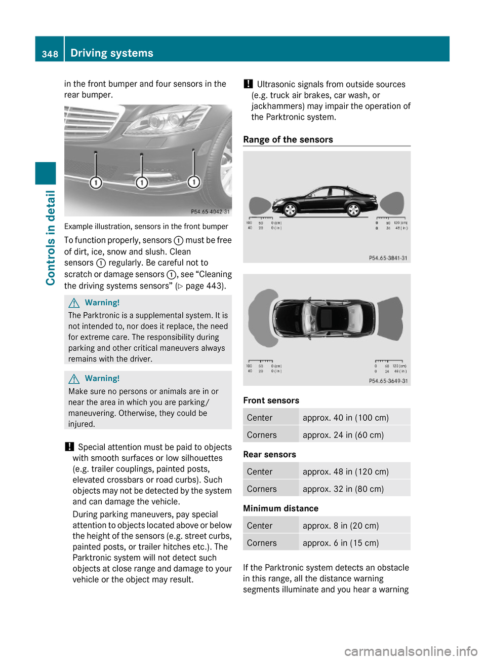
in the front bumper and four sensors in the
rear bumper.
Example illustration, sensors in the front bumper
To function properly, sensors : must be free
of dirt, ice, snow and slush. Clean
sensors : regularly. Be careful not to
scratch or damage sensors :, see “Cleaning
the driving systems sensors” (Y page 443).
GWarning!
The Parktronic is a supplemental system. It is
not intended to, nor does it replace, the need
for extreme care. The responsibility during
parking and other critical maneuvers always
remains with the driver.
GWarning!
Make sure no persons or animals are in or
near the area in which you are parking/
maneuvering. Otherwise, they could be
injured.
! Special attention must be paid to objects
with smooth surfaces or low silhouettes
(e.g. trailer couplings, painted posts,
elevated crossbars or road curbs). Such
objects may not be detected by the system
and can damage the vehicle.
During parking maneuvers, pay special
attention to objects located above or below
the height of the sensors (e.g. street curbs,
painted posts, or trailer hitches etc.). The
Parktronic system will not detect such
objects at close range and damage to your
vehicle or the object may result.
! Ultrasonic signals from outside sources
(e.g. truck air brakes, car wash, or
jackhammers) may impair the operation of
the Parktronic system.
Range of the sensors
Front sensors
Centerapprox. 40 in (100 cm)Cornersapprox. 24 in (60 cm)
Rear sensors
Centerapprox. 48 in (120 cm)Cornersapprox. 32 in (80 cm)
Minimum distance
Centerapprox. 8 in (20 cm)Cornersapprox. 6 in (15 cm)
If the Parktronic system detects an obstacle
in this range, all the distance warning
segments illuminate and you hear a warning
348Driving systemsControls in detail
221_AKB; 6; 20, en-USd2ugruen,Version: 2.11.8.12009-09-24T13:28:17+02:00 - Seite 348
Page 352 of 548
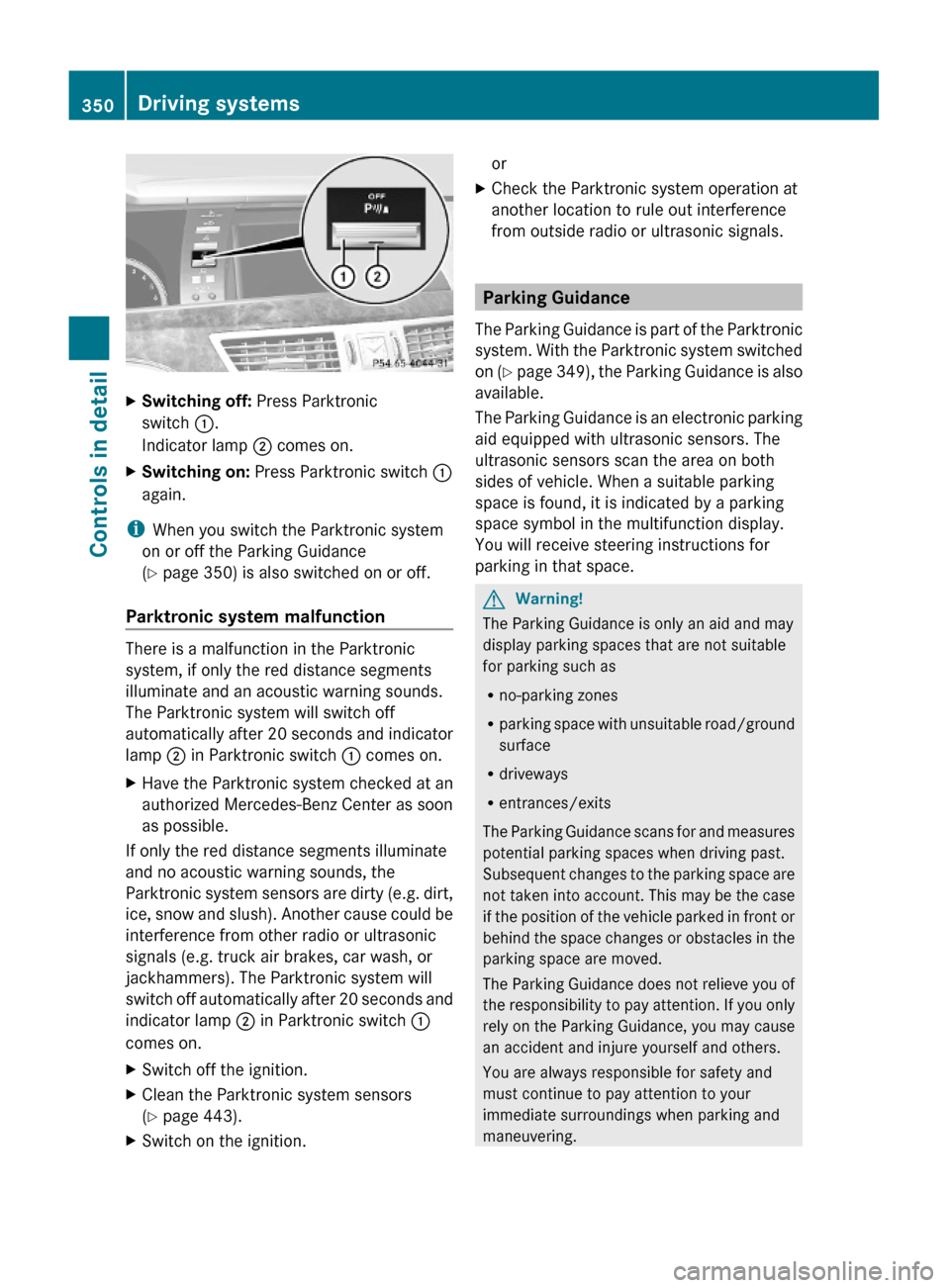
XSwitching off: Press Parktronic
switch :.
Indicator lamp ; comes on.
XSwitching on: Press Parktronic switch :
again.
iWhen you switch the Parktronic system
on or off the Parking Guidance
(Y page 350) is also switched on or off.
Parktronic system malfunction
There is a malfunction in the Parktronic
system, if only the red distance segments
illuminate and an acoustic warning sounds.
The Parktronic system will switch off
automatically after 20 seconds and indicator
lamp ; in Parktronic switch : comes on.
XHave the Parktronic system checked at an
authorized Mercedes-Benz Center as soon
as possible.
If only the red distance segments illuminate
and no acoustic warning sounds, the
Parktronic system sensors are dirty (e.g. dirt,
ice, snow and slush). Another cause could be
interference from other radio or ultrasonic
signals (e.g. truck air brakes, car wash, or
jackhammers). The Parktronic system will
switch off automatically after 20 seconds and
indicator lamp ; in Parktronic switch :
comes on.
XSwitch off the ignition.XClean the Parktronic system sensors
(Y page 443).
XSwitch on the ignition.orXCheck the Parktronic system operation at
another location to rule out interference
from outside radio or ultrasonic signals.
Parking Guidance
The Parking Guidance is part of the Parktronic
system. With the Parktronic system switched
on (Y page 349), the Parking Guidance is also
available.
The Parking Guidance is an electronic parking
aid equipped with ultrasonic sensors. The
ultrasonic sensors scan the area on both
sides of vehicle. When a suitable parking
space is found, it is indicated by a parking
space symbol in the multifunction display.
You will receive steering instructions for
parking in that space.
GWarning!
The Parking Guidance is only an aid and may
display parking spaces that are not suitable
for parking such as
Rno-parking zones
Rparking space with unsuitable road/ground
surface
Rdriveways
Rentrances/exits
The Parking Guidance scans for and measures
potential parking spaces when driving past.
Subsequent changes to the parking space are
not taken into account. This may be the case
if the position of the vehicle parked in front or
behind the space changes or obstacles in the
parking space are moved.
The Parking Guidance does not relieve you of
the responsibility to pay attention. If you only
rely on the Parking Guidance, you may cause
an accident and injure yourself and others.
You are always responsible for safety and
must continue to pay attention to your
immediate surroundings when parking and
maneuvering.
350Driving systemsControls in detail
221_AKB; 6; 20, en-USd2ugruen,Version: 2.11.8.12009-09-24T13:28:17+02:00 - Seite 350
Page 412 of 548
Mercedes-Benz Center immediately. Do
not add brake fluid as this will not solve the
problem. For more information, see
“Practical hints”.
When checking the brake fluid level, the
vehicle must be parked on level ground.
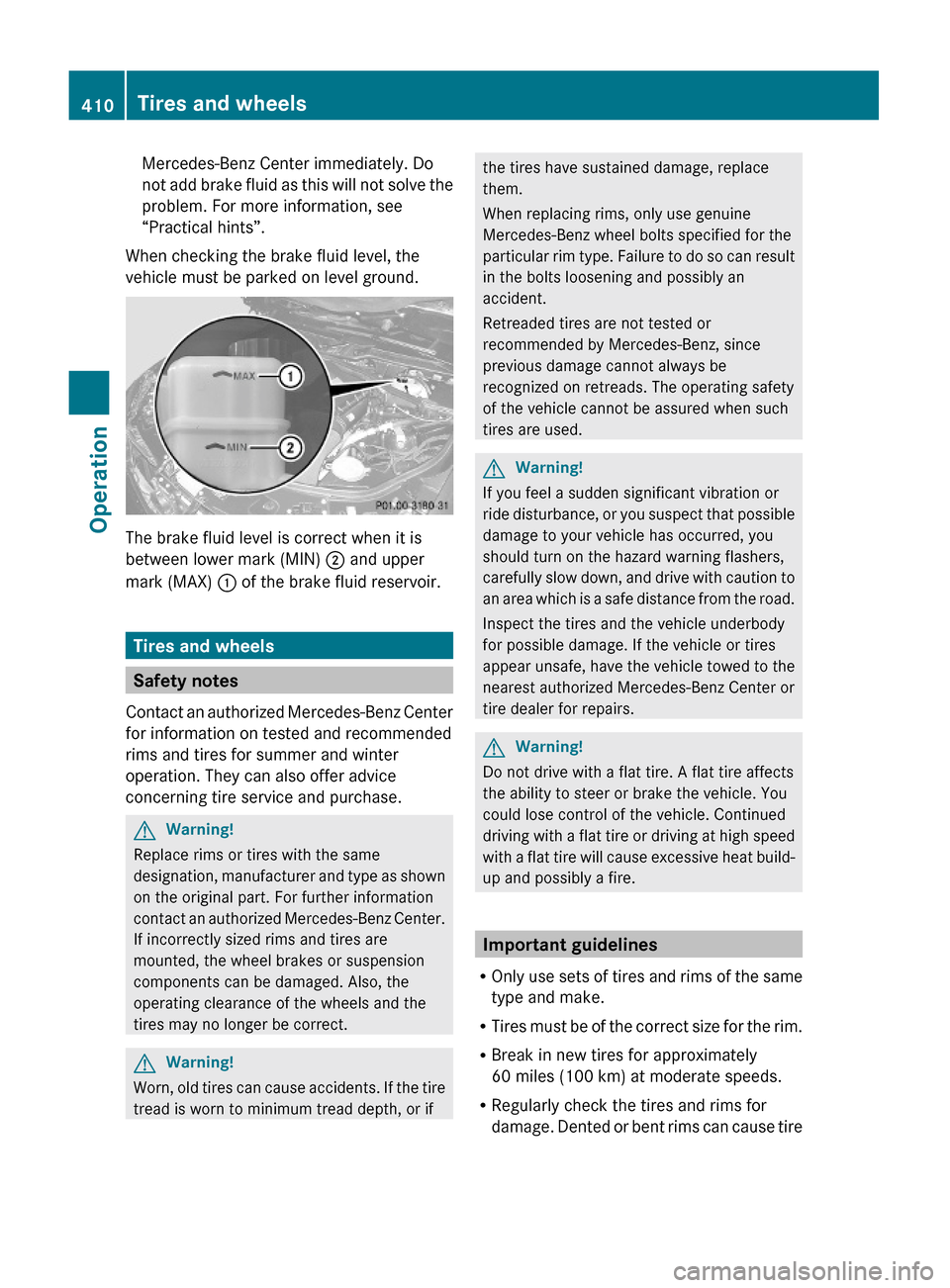
The brake fluid level is correct when it is
between lower mark (MIN) ; and upper
mark (MAX) : of the brake fluid reservoir.
Tires and wheels
Safety notes
Contact an authorized Mercedes-Benz Center
for information on tested and recommended
rims and tires for summer and winter
operation. They can also offer advice
concerning tire service and purchase.
GWarning!
Replace rims or tires with the same
designation, manufacturer and type as shown
on the original part. For further information
contact an authorized Mercedes-Benz Center.
If incorrectly sized rims and tires are
mounted, the wheel brakes or suspension
components can be damaged. Also, the
operating clearance of the wheels and the
tires may no longer be correct.
GWarning!
Worn, old tires can cause accidents. If the tire
tread is worn to minimum tread depth, or if
the tires have sustained damage, replace
them.
When replacing rims, only use genuine
Mercedes-Benz wheel bolts specified for the
particular rim type. Failure to do so can result
in the bolts loosening and possibly an
accident.
Retreaded tires are not tested or
recommended by Mercedes-Benz, since
previous damage cannot always be
recognized on retreads. The operating safety
of the vehicle cannot be assured when such
tires are used.
GWarning!
If you feel a sudden significant vibration or
ride disturbance, or you suspect that possible
damage to your vehicle has occurred, you
should turn on the hazard warning flashers,
carefully slow down, and drive with caution to
an area which is a safe distance from the road.
Inspect the tires and the vehicle underbody
for possible damage. If the vehicle or tires
appear unsafe, have the vehicle towed to the
nearest authorized Mercedes-Benz Center or
tire dealer for repairs.
GWarning!
Do not drive with a flat tire. A flat tire affects
the ability to steer or brake the vehicle. You
could lose control of the vehicle. Continued
driving with a flat tire or driving at high speed
with a flat tire will cause excessive heat build-
up and possibly a fire.
Important guidelines
ROnly use sets of tires and rims of the same
type and make.
RTires must be of the correct size for the rim.
RBreak in new tires for approximately
60 miles (100 km) at moderate speeds.
RRegularly check the tires and rims for
damage. Dented or bent rims can cause tire
410Tires and wheelsOperation
221_AKB; 6; 20, en-USd2ugruen,Version: 2.11.8.12009-09-24T13:28:17+02:00 - Seite 410
Page 416 of 548
can overheat them, possibly causing a
blowout. Overloading the tires can also result
in handling or steering problems, or brake
failure.
Check the tire inflation pressure at least once
a month.
Check and adjust the tire inflation pressure
when the tires are cold ( Y page 411).
Checking tire inflation pressure
manually
Follow the steps below to achieve correct tire
inflation pressure:
XRemove the cap from the valve on one tire.XFirmly press a tire gauge onto the valve.XRead the tire inflation pressure on the tire
gauge and check against the
recommended tire inflation pressure on the
Tire and Loading Information placard on the
driver’s door B-pillar ( Y page 418). If
necessary, add air to achieve the
recommended tire inflation pressure.XIf you have overfilled the tire, release tire
inflation pressure by pushing the metal
stem of the valve with e.g. a tip of a pen.
Then recheck the tire inflation pressure
with the tire gauge.XInstall the valve cap.XRepeat this procedure for each tire.
Advanced Tire Pressure Monitoring
System (Advanced TPMS)
Your vehicle is equipped with the Advanced
Tire Pressure Monitoring System (Advanced
TPMS). It measures the tire inflation pressure
in the vehicle’s tires and issues warnings in
case of pressure loss in one or more of the
tires.
The TPMS is equipped with a combination low
tire pressure/ TPMS malfunction telltale
(USA) or a low tire pressure telltale (Canada)
in the instrument cluster. Depending on how
the telltale illuminates, it indicates a low tire
pressure condition or a malfunction in the
TPMS system itself:
R If the telltale illuminates continuously, one
or more of your tires is significantly
underinflated. There is no malfunction in
the TPMS.
R USA only: If the telltale flashes for 60
seconds and then stays illuminated, the
TPMS system itself is not operating
properly.
The TPMS only functions on wheels that are
equipped with the proper electronic sensors.GWarning!
The TPMS does not indicate a warning for
wrongly selected inflation pressures. Always
adjust tire inflation pressure according to the
Tire and Loading Information placard or the
supplemental tire inflation pressure
information on the inside of the fuel filler flap.
The TPMS is not able to issue a warning due
to a sudden dramatic loss of pressure (e.g. tire
blowout caused by a foreign object). In this
case bring the vehicle to a halt by carefully
applying the brakes and avoiding abrupt
steering maneuvers.
GWarning!
Each tire, including the spare (if provided),
should be checked at least once a month
when cold and inflated to the inflation
pressure recommended by the vehicle
manufacturer on the Tire and Loading
Information placard on the driver’s door B-
pillar or the tire inflation pressure label on the
inside of the fuel filler flap. If your vehicle has
tires of a different size than the size indicated
on the Tire and Loading Information placard
or the tire inflation pressure label, you should
determine the proper tire inflation pressure
for those tires.
414Tires and wheelsOperation
221_AKB; 6; 20, en-USd2ugruen,Version: 2.11.8.12009-09-24T13:28:17+02:00 - Seite 414
Page 432 of 548
Tire type code
Tire type code ? may, at the option of the
manufacturer, be used as a descriptive code
for identifying significant characteristics of
the tire.
Date of manufacture
The date of manufacture A identifies the
week and year of manufacture.
The first two figures identify the week,
starting with “01” to represent the first full
week of the calendar year. The second two
figures represent the year.
For example, “3208” represents the 32nd
week of 2008.
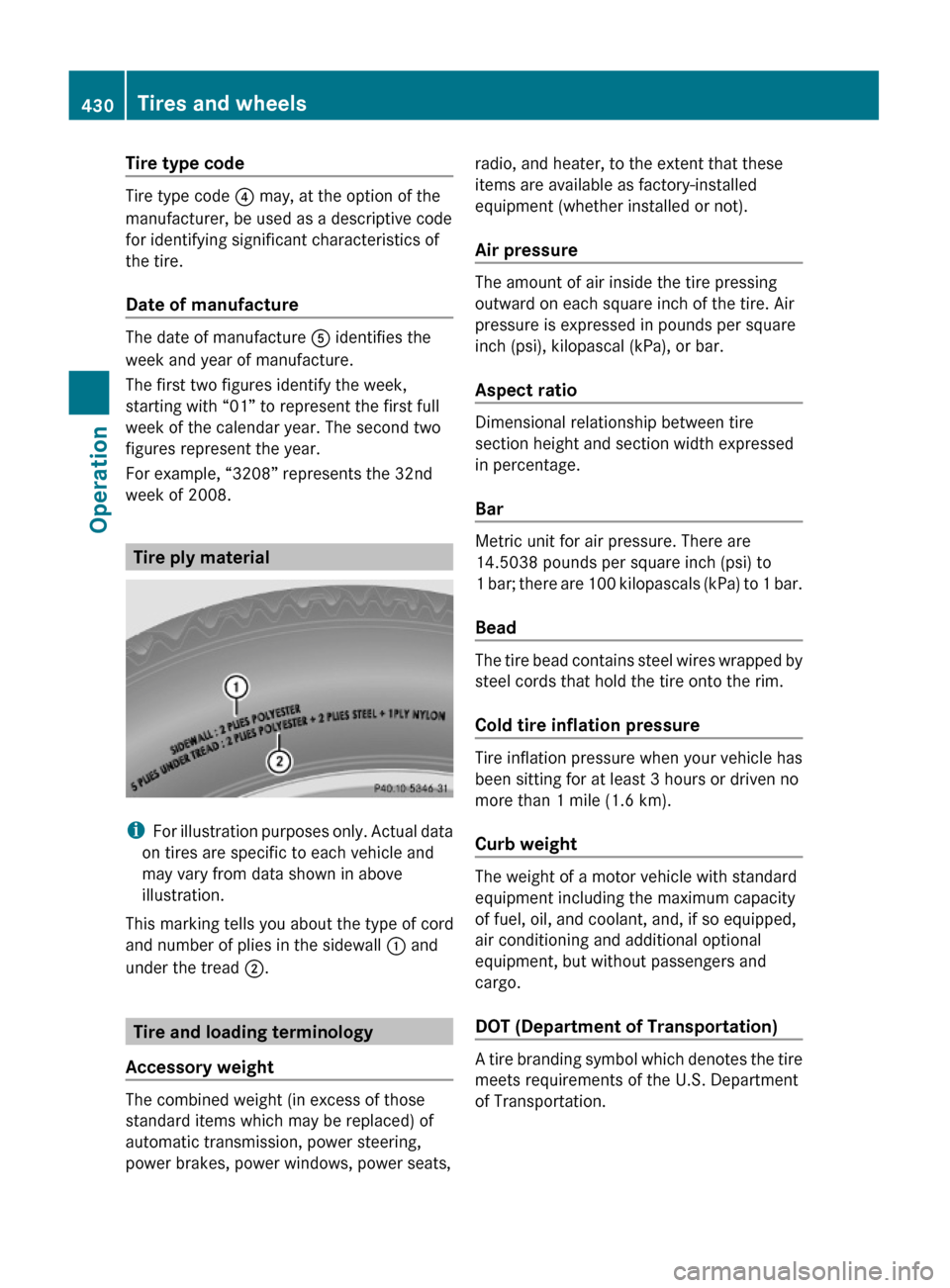
Tire ply material
iFor illustration purposes only. Actual data
on tires are specific to each vehicle and
may vary from data shown in above
illustration.
This marking tells you about the type of cord
and number of plies in the sidewall : and
under the tread ;.
Tire and loading terminology
Accessory weight
The combined weight (in excess of those
standard items which may be replaced) of
automatic transmission, power steering,
power brakes, power windows, power seats,
radio, and heater, to the extent that these
items are available as factory-installed
equipment (whether installed or not).
Air pressure
The amount of air inside the tire pressing
outward on each square inch of the tire. Air
pressure is expressed in pounds per square
inch (psi), kilopascal (kPa), or bar.
Aspect ratio
Dimensional relationship between tire
section height and section width expressed
in percentage.
Bar
Metric unit for air pressure. There are
14.5038 pounds per square inch (psi) to
1 bar; there are 100 kilopascals (kPa) to 1 bar.
Bead
The tire bead contains steel wires wrapped by
steel cords that hold the tire onto the rim.
Cold tire inflation pressure
Tire inflation pressure when your vehicle has
been sitting for at least 3 hours or driven no
more than 1 mile (1.6 km).
Curb weight
The weight of a motor vehicle with standard
equipment including the maximum capacity
of fuel, oil, and coolant, and, if so equipped,
air conditioning and additional optional
equipment, but without passengers and
cargo.
DOT (Department of Transportation)
A tire branding symbol which denotes the tire
meets requirements of the U.S. Department
of Transportation.
430Tires and wheelsOperation
221_AKB; 6; 20, en-USd2ugruen,Version: 2.11.8.12009-09-24T13:28:17+02:00 - Seite 430
Page 433 of 548
GAWR (Gross Axle Weight Rating)
The GAWR is the maximum permissible axle
weight. The gross vehicle weight on each axle
must never exceed the GAWR for the front
and rear axle indicated on the certification
label located on the driver’s door B-pillar.
GVW (Gross Vehicle Weight)
The GVW comprises the weight of the vehicle
including fuel, tools, spare wheel, installed
accessories, passengers and cargo and, if
applicable, trailer tongue load. The GVW must
never exceed the GVWR indicated on the
certification label located on the driver’s door
B-pillar.
GVWR (Gross Vehicle Weight Rating)
This is the maximum permissible vehicle
weight of the fully loaded vehicle (weight of
the vehicle including all options, passengers,
fuel, and cargo and, if applicable, trailer
tongue load). It is indicated on the
certification label located on the driver’s door
B-pillar.
Kilopascal (kPa)
Metric unit for air pressure. There are 6.9 kPa
to 1 psi; another metric unit for air pressure
is bar. There are 100 kilopascals (kPa) to
1 bar.
Load index
Numerical code associated with the
maximum load a tire can support.
Maximum load rating
The maximum load in kilograms and pounds
that can be carried by the tire.
Maximum loaded vehicle weight
The sum of curb weight, accessory weight,
total load limit, and production options
weight.
Maximum permissible tire inflation
pressure
This number is the greatest amount of air
pressure that should ever be put in the tire.
Normal occupant weight
The number of occupants the vehicle is
designed to seat, multiplied by 68 kilograms
(150 lb).
Occupant distribution
The distribution of occupants in a vehicle at
their designated seating positions.
Production options weight
The combined weight of those installed
regular production options weighing over
5 lbs (2.3 kilograms) in excess of those
standard items which they replace, not
previously considered in curb weight or
accessory weight, including heavy duty
brakes, ride levelers, roof rack, heavy duty
battery, and special trim.
PSI (Pounds per square inch)
A standard unit of measure for air pressure.
Recommended tire inflation pressure
The recommended tire inflation pressure for
normal driving conditions is listed on the Tire
and Loading Information placard located on
the driver’s door B-pillar. It provides best
handling, tread life and riding comfort.
Supplemental information pertaining to
special driving situations can be found on the
tire inflation pressure label on the inside of
the fuel filler flap.
Rim
A metal support for a tire or a tire and tube
assembly upon which the tire beads are
seated.
Tires and wheels431Operation221_AKB; 6; 20, en-USd2ugruen,Version: 2.11.8.12009-09-24T13:28:17+02:00 - Seite 431Z