2010 MERCEDES-BENZ S CLASS service
[x] Cancel search: servicePage 394 of 548
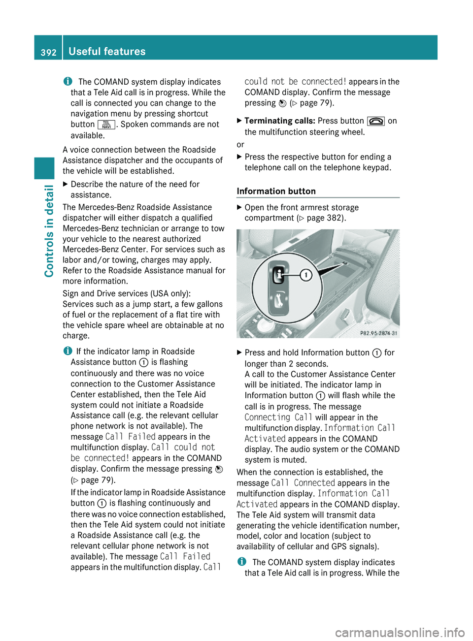
i The COMAND system display indicates
that a Tele Aid call is in progress. While the
call is connected you can change to the
navigation menu by pressing shortcut
button \000X. Spoken commands are not
available.
A voice connection between the Roadside
Assistance dispatcher and the occupants of
the vehicle will be established.
XDescribe the nature of the need for
assistance.
The Mercedes-Benz Roadside Assistance
dispatcher will either dispatch a qualified
Mercedes-Benz technician or arrange to tow
your vehicle to the nearest authorized
Mercedes-Benz Center. For services such as
labor and/or towing, charges may apply.
Refer to the Roadside Assistance manual for
more information.
Sign and Drive services (USA only):
Services such as a jump start, a few gallons
of fuel or the replacement of a flat tire with
the vehicle spare wheel are obtainable at no
charge.
iIf the indicator lamp in Roadside
Assistance button \000F is flashing
continuously and there was no voice
connection to the Customer Assistance
Center established, then the Tele Aid
system could not initiate a Roadside
Assistance call (e.g. the relevant cellular
phone network is not available). The
message Call Failed appears in the
multifunction display. Call could not
be connected! appears in the COMAND
display. Confirm the message pressing \000
Page 395 of 548
call is connected you can change to the
navigation menu by pressing shortcut
button 0058. Spoken commands are not
available.
A voice connection between the Customer
Assistance Center representative and the
occupants of the vehicle will be established.
Information regarding the operation of your
vehicle, the nearest authorized Mercedes-
Benz Center or Mercedes-Benz USA products
and services is available to you.
For more details concerning the Tele Aid
system, please visit www.mbusa.com (USA
only), log in to “Owner’s Online” and visit the
“My Tele Aid” section to learn more.
i If the indicator lamp in Information
button 0046 is flashing continuously and
there was no voice connection established,
then the Tele Aid system could not initiate
an Information call (e.g. the relevant
cellular phone network is not available).
The message Call Failed appears in the
multifunction display. Call could not
be connected! appears in the COMAND
display. Confirm the message pressing 00A1
( Y page 79).XTerminating calls: Press button 007F on
the multifunction steering wheel.
or
XPress the respective button for ending a
telephone call on the telephone keypad.
Call priority
If other service calls such as a Roadside
Assistance call or Information call are active,
an emergency call is still possible. In this
case, the emergency call will take priority and
override all other active calls.
The indicator lamp in the respective button
flashes until the call is concluded. Automatic
initiated emergency calls can only be
terminated by a Customer Assistance Center
representative. All other calls can be
terminated by pressing button 007F on the
multifunction steering wheel or the
respective button for ending a telephone call
on the telephone keypad.
Destination Download to the COMAND
system
i The components and operating principles
of the COMAND system can be found on
( Y page 77).
Destination Download allows you access to a
database of over 10 million points of interest
(POIs) that can be downloaded to your
vehicle’s navigation system. If you know the
destination, the address can be downloaded,
or can be provided with points of interests
near your location.
Route guidance
You will be prompted to confirm that route
guidance to the entered address is to be
started.
XSlide 00A0005B 0050 or rotate 0082005B 0083 to select Yes
menu item and confirm by pressing 00A1.
The system calculates the route and
subsequently starts the route guidance to the
defined address.
i If you select No, you can save the address
to your address book.
i The Destination Download feature is
available if the relevant mobile phone
network is available and data connection is
possible.
Search & Send
i In order to utilize Search & Send your
vehicle must be equipped with Tele Aid,
Navigation, and an active Tele Aid
subscription.
“Search & Send” is a navigation destination
address entry service. A destination address
located using Google Maps ®
or Yahoo Local
Maps ®
websites can be delivered via Tele Aid
Useful features393Controls in detail221_AKB; 6; 20, en-USd2ugruen,Version: 2.11.8.12009-09-24T13:28:17+02:00 - Seite 393Z
Page 397 of 548
The vehicle can be remotely locked within
four days after the ignition has been switched
off.XContact the Customer Assistance Center
at 1-800-FOR-MERCedes
(1-800-367-6372) (USA only) or
1-888-923-8367 (Canada only).
You will be asked to provide your password.
When you are inside your vehicle the next
time and switch on the ignition, the message
Tele Aid Doors Locked Remotely will
appear on the multifunction display.
i The remote door lock feature is available
if the relevant cellular phone network is
available and data connection is possible.
Automatic Maintenance Call
Your vehicle is equipped with a feature that
considerably enhances vehicle care. Just
prior to reaching a vehicle maintenance
milestone, Tele Aid transmits important
vehicle maintenance information that alerts
your authorized Mercedes-Benz Center of
required service. This is automatic and does
not require driver intervention. This feature
allows your preferred Mercedes-Benz Center
to significantly improve the process of
arranging your service appointment and
ensures that your vehicle receives the best
possible care.
i The Automatic Maintenance Call feature
is available if the relevant telephone
network is available and data connection is
possible.
Stolen Vehicle Recovery Services
In the event your vehicle was stolen:
XReport the incident to the police.
The police will issue a numbered incident
report.XPass this number on to the Customer
Assistance Center along with your
password.
The Customer Assistance Center will then
attempt to covertly contact the vehicle’s
Tele Aid system. Once the vehicle is
located, the Customer Assistance Center
will contact the local law enforcement and
you. The vehicle’s location will only be
provided to law enforcement.
i If the anti-theft alarm stays on for more
than 30 seconds, the Tele Aid system will
notify the Customer Assistance Center
automatically.
Garage door opener
The integrated remote control can operate up
to three separately controlled devices
compatible with HomeLink ®
or some other
systems.
GWarning!
Before programming the integrated remote
control to a garage door opener or gate
operator, make sure people and objects are
out of the way of the device to prevent
potential harm or damage. When
programming a garage door opener, the door
moves up or down. When programming a gate
operator, the gate opens or closes.
Do not use the integrated remote control with
any garage door opener that lacks safety stop
and reverse features as required by U.S.
federal safety standards (this includes any
garage door opener model manufactured
before April 1, 1982). A garage door that
cannot detect an object - signaling the door
to stop and reverse - does not meet current
U.S. federal safety standards.
Useful features395Controls in detail221_AKB; 6; 20, en-USd2ugruen,Version: 2.11.8.12009-09-24T13:28:17+02:00 - Seite 395Z
Page 400 of 548
Reprogramming a single signal
transmitter button
To program a device using a signal
transmitter button previously trained, follow
these steps:
XSwitch on the ignition.XPress and hold the desired signal
transmitter button ( 0047, 008A or 0088). Do not
release the button.
Indicator lamp 0046 will begin to flash after
20 seconds.XWithout releasing the signal transmitter
button, proceed with programming starting
with step 3.
Operation of integrated remote control
XSwitch on the ignition.XSelect and press the appropriate
integrated signal transmitter button ( 0047,
008A or 0088) to activate the remote controlled
device.
The integrated remote control transmitter
continues to send the signal as long as the
button is pressed – up to 20 seconds.
Erasing the integrated remote control
memory
i If you sell your vehicle, erase the codes of
all three channels.
XSwitch on the ignition.XSimultaneously press and hold outer signal
transmitter buttons 0047 and 0088, for
approximately 20 seconds, until indicator
lamp 0046 flashes rapidly. Do not hold for
longer than 30 seconds.
The codes of all three channels are erased.Programming tips
If you are having difficulty programming the
integrated remote control, here are some
helpful tips:
R Check the frequency of hand-held remote
control 0086 (typically located on the reverse
side of the remote). The integrated remote
control is compatible with radio-frequency
devices operating between 280-390 MHz.
R Put a new battery in hand-held remote
control 0086. This will increase the likelihood
of the hand-held remote control sending a
stronger and more accurate signal to the
integrated remote control.
R While performing step 3, hold hand-held
remote control 0086 at different lengths and
angles from the signal transmitter button
( 0047 , 008A or 0088) you are programming.
Attempt varying angles at the distance of 2
to 12 inches (5 to 30 cm) away or the same
angle at varying distances.
R If another hand-held remote control is
available for the same device, try the
programming steps again using that other
hand-held remote control. Make sure new
batteries are in the hand-held remote
control before beginning the procedure.
R Straighten the antenna wire from the
garage door opener assembly. This may
help improve transmitting and/or receiving
signals.
i Certain types of garage door openers are
incompatible with the integrated remote
control. If you should experience further
difficulties with programming the
integrated remote control, contact an
authorized Mercedes-Benz Center, or call
the Mercedes-Benz Customer Assistance
Center (USA only) at
1-800-FOR-MERCedes (1-800-367-6372),
or the HomeLink ®
Hotline (USA only) at
1-800-355-3515, or the Customer Service
(Canada only) at 1-800-387-0100.
398Useful featuresControls in detail
221_AKB; 6; 20, en-USd2ugruen,Version: 2.11.8.12009-09-24T13:28:17+02:00 - Seite 398
Page 412 of 548

Mercedes-Benz Center immediately. Do
not add brake fluid as this will not solve the
problem. For more information, see
“Practical hints”.
When checking the brake fluid level, the
vehicle must be parked on level ground.
The brake fluid level is correct when it is
between lower mark (MIN) \000G and upper
mark (MAX) \000F of the brake fluid reservoir.
Tires and wheels
Safety notes
Contact an authorized Mercedes-Benz Center
for information on tested and recommended
rims and tires for summer and winter
operation. They can also offer advice
concerning tire service and purchase.
GWarning!
Replace rims or tires with the same
designation, manufacturer and type as shown
on the original part. For further information
contact an authorized Mercedes-Benz Center.
If incorrectly sized rims and tires are
mounted, the wheel brakes or suspension
components can be damaged. Also, the
operating clearance of the wheels and the
tires may no longer be correct.
GWarning!
Worn, old tires can cause accidents. If the tire
tread is worn to minimum tread depth, or if
the tires have sustained damage, replace
them.
When replacing rims, only use genuine
Mercedes-Benz wheel bolts specified for the
particular rim type. Failure to do so can result
in the bolts loosening and possibly an
accident.
Retreaded tires are not tested or
recommended by Mercedes-Benz, since
previous damage cannot always be
recognized on retreads. The operating safety
of the vehicle cannot be assured when such
tires are used.
GWarning!
If you feel a sudden significant vibration or
ride disturbance, or you suspect that possible
damage to your vehicle has occurred, you
should turn on the hazard warning flashers,
carefully slow down, and drive with caution to
an area which is a safe distance from the road.
Inspect the tires and the vehicle underbody
for possible damage. If the vehicle or tires
appear unsafe, have the vehicle towed to the
nearest authorized Mercedes-Benz Center or
tire dealer for repairs.
GWarning!
Do not drive with a flat tire. A flat tire affects
the ability to steer or brake the vehicle. You
could lose control of the vehicle. Continued
driving with a flat tire or driving at high speed
with a flat tire will cause excessive heat build-
up and possibly a fire.
Important guidelines
ROnly use sets of tires and rims of the same
type and make.
RTires must be of the correct size for the rim.
RBreak in new tires for approximately
60 miles (100 km) at moderate speeds.
RRegularly check the tires and rims for
damage. Dented or bent rims can cause tire
410Tires and wheelsOperation
221_AKB; 6; 20, en-USd2ugruen,Version: 2.11.8.12009-09-24T13:28:17+02:00 - Seite 410
Page 417 of 548

As an added safety feature, your vehicle has
been equipped with a tire pressure monitoring
system (TPMS) that illuminates a low tire
pressure telltale when one or more of your
tires are significantly underinflated.
Accordingly, when the low tire pressure
telltale illuminates, you should stop and check
your tires as soon as possible, and inflate
them to the proper pressure. Driving on a
significantly underinflated tire causes the tire
to overheat and can lead to tire failure.
Underinflation also reduces fuel efficiency
and tire tread life, and may affect the vehicle’s
handling and stopping ability. Please note that
the TPMS is not a substitute for proper tire
maintenance, and it is the driver’s
responsibility to maintain correct tire
pressure, even if underinflation has not
reached the level to trigger illumination of the
TPMS low tire pressure telltale.
USA only:
Your vehicle has also been equipped with a
TPMS malfunction indicator to indicate when
the system is not operating properly. The
TPMS malfunction indicator is combined with
the low tire pressure telltale. When the
system detects a malfunction, the telltale will
flash for approximately 1 minute and then
remain continuously illuminated. This
sequence will continue upon subsequent
vehicle start-ups as long as the malfunction
exists. When the malfunction indicator is
illuminated, the system may not be able to
detect or signal low tire pressure as intended.
TPMS malfunctions may occur for a variety of
reasons, including the installation of
incompatible replacement or alternate tires
or wheels on the vehicle that prevent the
TPMS from functioning properly. Always
check the TPMS malfunction telltale after
replacing one or more tires or wheels on your
vehicle to ensure that the replacement or
alternate tires and wheels allow the TPMS to
continue to function properly.
iUSA only:
If a condition causing the TPMS to
malfunction develops, it may take up to
10 minutes for the system to signal a
malfunction using the TPMS telltale
flashing and illumination sequence.
The telltale extinguishes after a few
minutes driving if the malfunction has been
corrected.
Tire pressure inquiries are made using the
multifunction display. The current tire
inflation pressure for each tire appears in the
multifunction display after a few minutes of
driving.
iPossible differences between the
readings of a tire pressure gauge of an air
hose, e.g. gas station equipment, and the
vehicle’s control system can occur. The tire
pressure displayed by the control system
apply to sea level. In high-altitude
locations, the reading on a tire pressure
gauge will be higher than the reading issued
by the vehicle’s control system. Do not
reduce the tire inflation pressure under
such circumstances.
XSwitch on the ignition.XPress button \000@ or \000> on the
multifunction steering wheel to select the
Service menu (Y page 233).
XPress button \000< or \000= to select Tire
Press..
XPress button \000d.
The current inflation pressure for each tire
appears in the multifunction display.
Example illustration
When the vehicle has been parked for longer
than 20 minutes, the message Tire
Tires and wheels415Operation221_AKB; 6; 20, en-USd2ugruen,Version: 2.11.8.12009-09-24T13:28:17+02:00 - Seite 415Z
Page 419 of 548
driver’s door B-pillar. Some vehicles may have
supplemental tire inflation pressure
information for driving at high speeds or for
vehicle loads less than the maximum loaded
vehicle condition. If such information is
provided, it can be found on the inside of the
fuel filler flap.
XUsing the Tire and Loading Information
placard on the driver’s door B-pillar
(Y page 418) or the supplemental tire
inflation pressure information on the inside
of the fuel filler flap, make sure the tire
inflation pressure of all four tires is correct.
XSwitch on the ignition.XPress button \000@ or \000> on the
multifunction steering wheel to select the
Service menu.
XPress button \000< or \000= on the
multifunction steering wheel to select
Tire Press..
XPress button \000d.
The current inflation pressure for each tire
appears in the multifunction display or the
following message appears in the
multifunction display:
Tire Pressure
Displayed After Driving
A Few Minutes
XPress button \000=.
The following message appears in the
multifunction display:
Use Current
Pressures As New
Reference Values
Press 'OK' to Confirm
XPress button \000d.
The following message appears in the
multifunction display:
Tire Pressure Monitor
Reactivated
After driving a few minutes the system
verifies that the current tire inflation
pressures are within the system’s specified
range. Afterwards the current tire inflation
pressures are accepted as reference values
and then monitored.
XIf you wish to cancel: Press button \000A.
or
XPress button \000< to exit the menu screen.
iWhen the wheel positions have been
changed, the inflation pressure of a tire
may be displayed for the wrong position
temporarily. After driving for a few minutes,
the inflation pressure will be shown for the
correct position.
Maximum tire inflation pressure
GWarning!
Never exceed the maximum tire inflation
pressure. Follow recommended tire inflation
pressures.
Do not underinflate tires. Underinflated tires
wear excessively and/or unevenly, adversely
affect handling and fuel economy, and are
more likely to fail from being overheated.
Do not overinflate tires. Overinflated tires can
adversely affect handling and ride comfort,
wear unevenly, increase stopping distance,
and result in sudden deflation (blowout)
because they are more likely to become
punctured or damaged by road debris,
potholes etc.
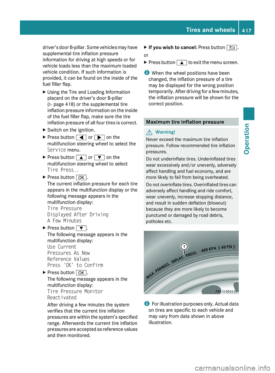
iFor illustration purposes only. Actual data
on tires are specific to each vehicle and
may vary from data shown in above
illustration.
Tires and wheels417Operation221_AKB; 6; 20, en-USd2ugruen,Version: 2.11.8.12009-09-24T13:28:17+02:00 - Seite 417Z
Page 425 of 548
Tire care and maintenanceGWarning!
Regularly check the tires for damage.
Damaged tires can cause tire inflation
pressure loss. As a result, you could lose
control of your vehicle.
Worn, old tires can cause accidents. If the tire
tread is worn to minimum tread depth, or if
the tires have sustained damage, replace
them.
Check the tire inflation pressure at least once
a month. For more information on checking
tire inflation pressure, see “Recommended
tire inflation pressure” (Y page 411).
Tire inspection
Every time you check the tire inflation
pressure, you should also inspect your tires
for the following:
Rexcessive treadwear (Y page 423)
Rcord or fabric showing through the tire’s
rubber
Rbumps, bulges, cuts, cracks or splits in the
tread or side of the tire
Replace the tire if you find any of the above
conditions.
Make sure you also inspect the spare tire
periodically for condition and inflation. Spare
tires will age and become worn over time even
if never used, and thus should be inspected
and replaced when necessary.
Life of tire
GWarning!
Tires and spare tire should be replaced after
6 years, regardless of the remaining tread.
The service life of a tire is dependent upon
varying factors including but not limited to:
RDriving style
RTire inflation pressure
RDistance driven
Tread depth GWarning!
Although the applicable federal motor vehicle
safety laws consider a tire to be worn when
the treadwear indicators (TWI) become visible
at approximately 1/16 in (1.6 mm), we
recommend that you do not allow your tires
to wear down to that level. As tread depth
approaches 1/8 in (3 mm), the adhesion
properties on a wet road are sharply reduced.
Depending upon the weather and/or road
surface (conditions), the tire traction varies
widely.
Do not allow your tires to wear down too far.
Adhesion properties on wet roads are sharply
reduced at tread depths of less than 1/8 in
(3 mm).
Treadwear indicators (TWI) are required by
law. These indicators are located in six places
on the tread circumference and become
visible at a tread depth of approximately1/16 in (1.6 mm), at which point the tire is
considered worn and should be replaced.
The recommended minimum tire tread depth
for summer tires is 1/8 in (3 mm). The
recommended minimum tire tread depth for
winter tires is 1/6 in (4 mm).
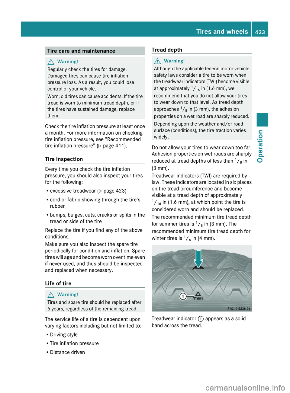
Treadwear indicator \000F appears as a solid
band across the tread.
Tires and wheels423Operation221_AKB; 6; 20, en-USd2ugruen,Version: 2.11.8.12009-09-24T13:28:17+02:00 - Seite 423Z