2010 MERCEDES-BENZ R320 center console
[x] Cancel search: center consolePage 125 of 364
Adjusting the instrument cluster
illumination
X To brighten illumination: Press and hold
button = until the desired level of
illumination is reached.
X To dim illumination: Press and hold
button : until the desired level of
illumination is reached.
i The instrument cluster illumination is
dimmed
or brightened automatically to suit
ambient light conditions.
The instrument cluster illumination will also
be adjusted automatically when you switch
on the vehicle’s exterior lamps.
i With the exterior lighting switched on, the
brightness of the switches in the center
console will also be adjusted when using
button : or =. Resetting trip odometer
X Make sure you are viewing the standard
display
(Y page 126) in the multifunction
display.
X Press and hold the reset button in the
instrument cluster
(Y page 122) until the
trip odometer is reset. Tachometer
The red marking on the tachometer
(Y
page 29) denotes excessive engine speed.
! Avoid driving at excessive engine speeds,
as it may result in serious engine damage
that is not covered by the Mercedes-Benz
Limited Warranty.
To help protect the engine, the fuel supply is
interrupted if the engine is operated within
the red marking. Control system
Introduction
The
control system is activated as soon as the
starter switch is in position 1 (Y page 79).
The control system enables you to call up
information about your vehicle and to change
vehicle settings.
For example, you can use the control system
to find out when your vehicle is next due for
maintenance service, to set the language for
messages in the instrument cluster display,
and much more. G
Warning!
A driver’s attention to the road and traffic
conditions must always be his/her primary
focus when driving.
For your safety and the safety of others,
selecting features through the multifunction
steering wheel should only be done by the
driver
when traffic and road conditions permit
it to be done safely.
Bear in mind that at a speed of just 30 mph
(approximately 50 km/h), your vehicle is
covering a distance of 44 feet (approximately
14 m) every second.
The control system relays information to the
multifunction display. Multifunction steering wheel
The displays in the multifunction display and
the settings in the control system are
controlled by using the buttons on the
multifunction steering wheel. Control system
123Controls in detail
251_AKB; 4; 52, en-US
d2ureepe, Version: 2.11.8.1 2009-03-23T09:22:52+01:00 - Seite 123 Z
Page 156 of 364

Indicator lamps ; and = are off.
R SPORT (for sporty driving)
Indicator lamp ; comes on.
R COMF (for comfort driving)
Indicator lamp = comes on.
X Start the engine.
X Press ADS switch : repeatedly until the
desired suspension tuning is reached.
The setting remains stored when you turn off
the engine. Vehicle level control
Your vehicle automatically adjusts its ride
height.
The all-around vehicle level control provides
best possible suspension and constant
ground clearance. The vehicle lowers at high
speed automatically in order to increase
driving safety and to reduce fuel
consumption.
Changes to the vehicle level should be made
while the vehicle is moving. The vehicle will
then reach the set level as fast as possible.
When you park the vehicle and the ambient
temperature changes, the vehicle level may
change visibly. When the temperature drops,
the vehicle lowers. When the temperature
rises, the vehicle raises.
The vehicle begins adjusting to the set vehicle
level as soon as the doors or tailgate are
unlocked or opened or closed with the vehicle
unlocked.
For major changes in vehicle level, the engine
must be running. G
Warning!
Make sure no one is near the wheel housing
or under the vehicle when you lower the
vehicle while it is standing still. Limbs could
become wedged into or under the vehicle.
For safety reasons, the vehicle can only be
lowered with all doors and the tailgate closed.
Lowering is interrupted if a door or the tailgate is opened and will continue after the door is
closed again.
! Keep in mind that on rough or uneven
roads, adjusting the vehicle to a lower level
may cause the vehicle underbody to come
in contact with the road and result in
damage to the vehicle underbody. Always
make sure the vehicle has sufficient ground
clearance before adjusting it to a lower
level.
! Before jacking up the vehicle with
equipment that lifts one or more of the
wheels completely off of the ground,
remove the SmartKey from the starter
switch.
i The activation threshold is defined by the
ADS setting (Y page 153). Basic settings
The following vehicle chassis ride heights can
be selected using vehicle level control
switch : in the center console:
Level Driving situation
Raised level For driving on rough roads.
Indicator lamp ; is on.
Highway
level For driving on paved roads
in fair or better condition.
Indicator lamp ; is off.154
Driving systemsControls in detail
251_AKB; 4; 52, en-US
d2ureepe,
Version: 2.11.8.1 2009-03-23T09:22:52+01:00 - Seite 154
Page 165 of 364
For best possible performance of the climate
control:
X
Keep the air intake grille in front of the
windshield free of snow, leaves, sticks, and
any other debris.
X Always keep all air vents and grilles in the
passenger compartment free from
obstruction.
i For draft-free ventilation, move the
adjustable center and side air vents to the
middle position.
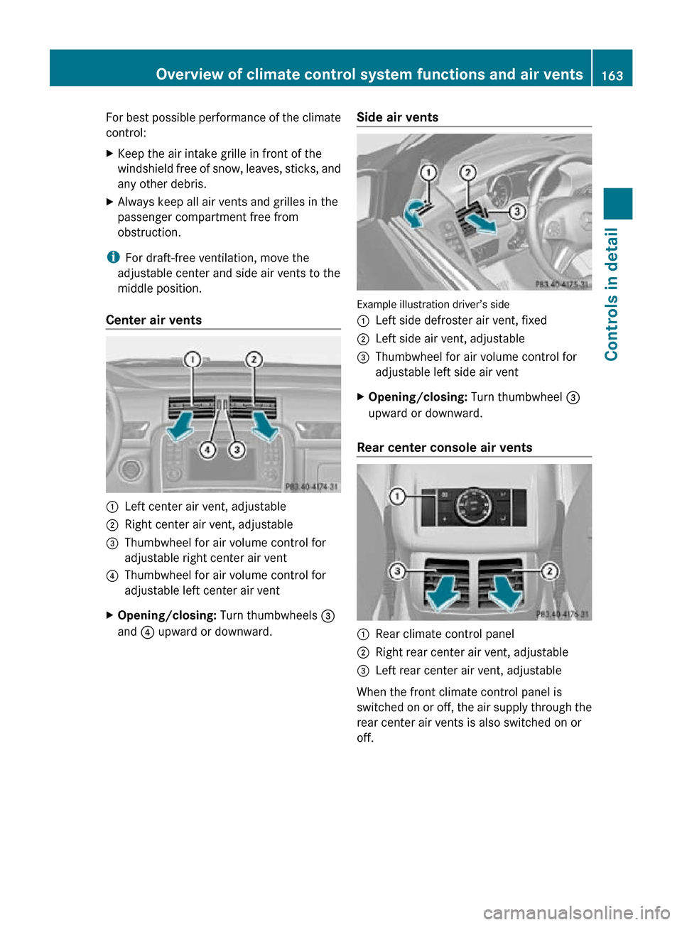
Center air vents :
Left center air vent, adjustable
; Right center air vent, adjustable
= Thumbwheel for air volume control for
adjustable right center air vent
? Thumbwheel for air volume control for
adjustable left center air vent
X Opening/closing: Turn thumbwheels =
and ? upward or downward. Side air vents Example illustration driver’s side
:
Left side defroster air vent, fixed
; Left side air vent, adjustable
= Thumbwheel for air volume control for
adjustable left side air vent
X Opening/closing: Turn thumbwheel =
upward or downward.
Rear center console air vents :
Rear climate control panel
; Right rear center air vent, adjustable
= Left rear center air vent, adjustable
When the front climate control panel is
switched on or off, the air supply through the
rear center air vents is also switched on or
off. Overview of climate control system functions and air vents
163Controls in detail
251_AKB; 4; 52, en-US
d2ureepe,Version: 2.11.8.1 2009-03-23T09:22:52+01:00 - Seite 163 Z
Page 193 of 364
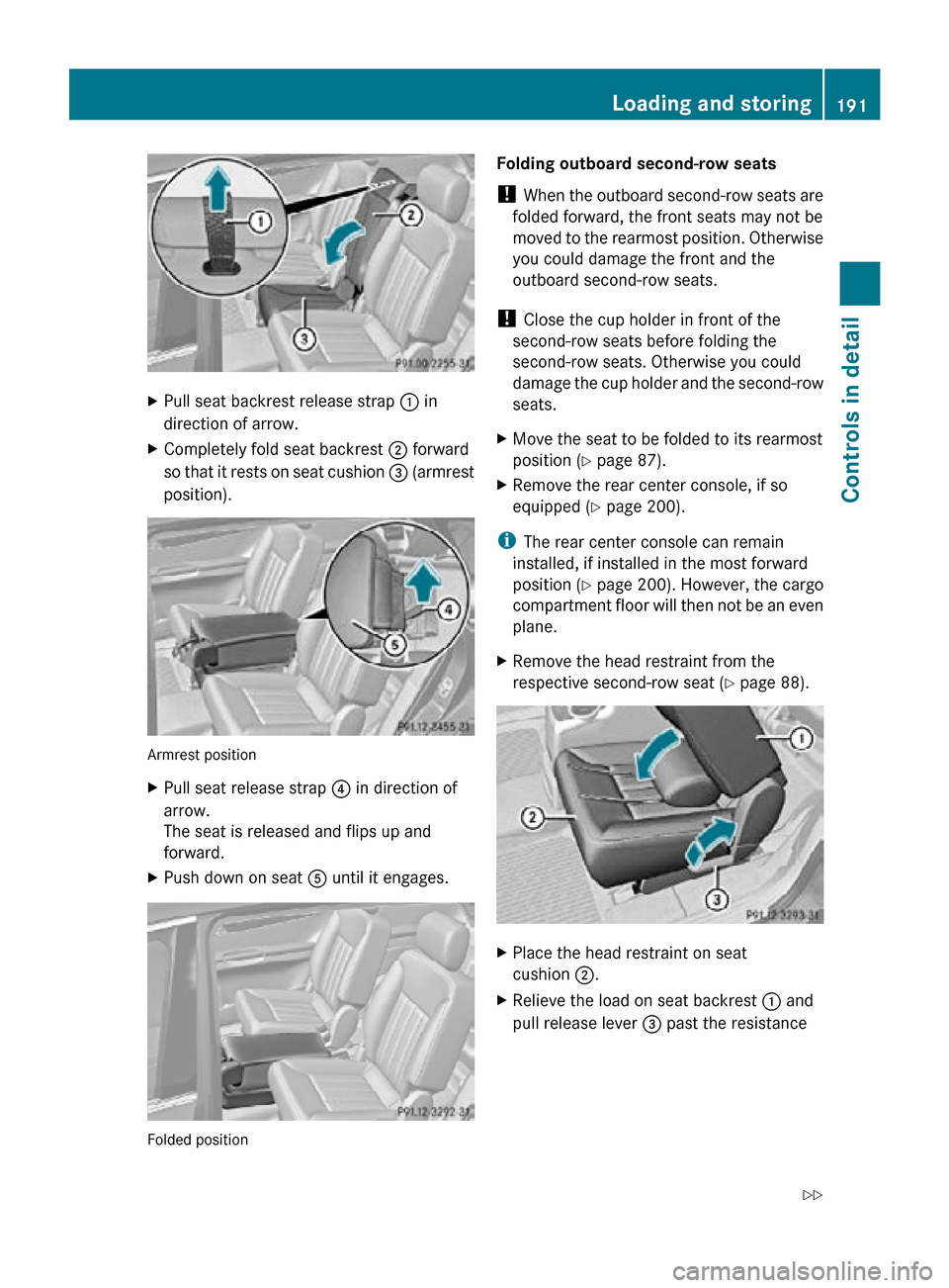
X
Pull seat backrest release strap : in
direction of arrow.
X Completely fold seat backrest ; forward
so that it rests on seat cushion = (armrest
position). Armrest position
X
Pull seat release strap ? in direction of
arrow.
The seat is released and flips up and
forward.
X Push down on seat A until it engages. Folded position Folding outboard second-row seats
!
When the outboard second-row seats are
folded forward, the front seats may not be
moved to the rearmost position. Otherwise
you could damage the front and the
outboard second-row seats.
! Close the cup holder in front of the
second-row seats before folding the
second-row seats. Otherwise you could
damage the cup holder and the second-row
seats.
X Move the seat to be folded to its rearmost
position (Y page 87).
X Remove the rear center console, if so
equipped ( Y page 200).
i The rear center console can remain
installed, if installed in the most forward
position ( Y page 200). However, the cargo
compartment floor will then not be an even
plane.
X Remove the head restraint from the
respective second-row seat (Y page 88). X
Place the head restraint on seat
cushion ;.
X Relieve the load on seat backrest : and
pull release lever = past the resistance Loading and storing
191Controls in detail
251_AKB; 4; 52, en-US
d2ureepe, Version: 2.11.8.1 2009-03-23T09:22:52+01:00 - Seite 191 Z
Page 200 of 364
Keep compartment lids closed. This will help
to prevent stored objects from being thrown
about and injuring vehicle occupants during
R
braking
R vehicle maneuvers
R an accident
Glove box Depending on vehicle equipment, an AUX
socket or a media interface is located in the
glove box. For information on Audio AUX
mode or on media interface, see separate
COMAND system operating instructions.
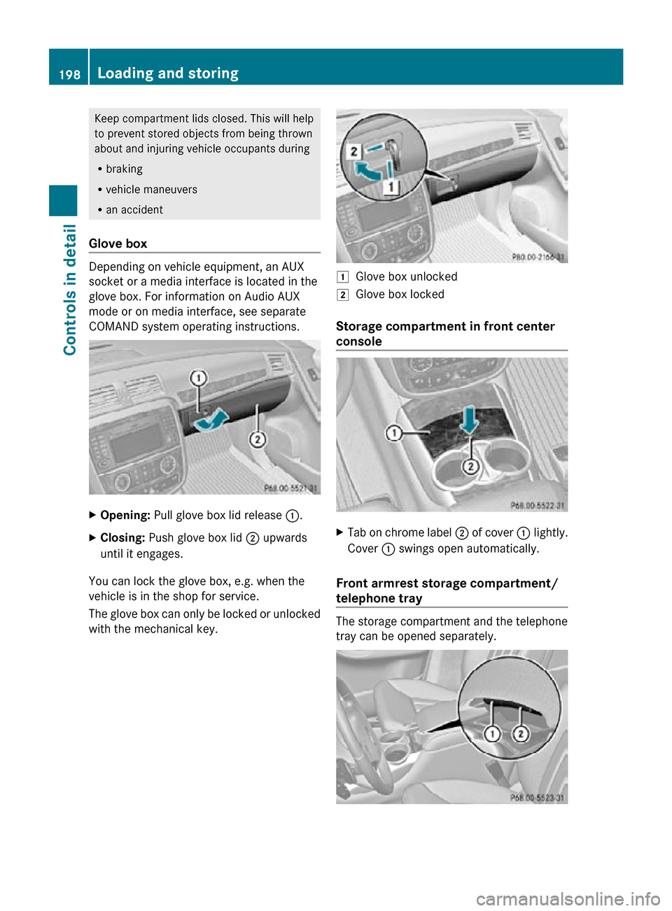
X
Opening: Pull glove box lid release :.
X Closing: Push glove box lid ; upwards
until it engages.
You can lock the glove box, e.g. when the
vehicle is in the shop for service.
The glove box can only be locked or unlocked
with the mechanical key. 1
Glove box unlocked
2 Glove box locked
Storage compartment in front center
console X
Tab on chrome label ; of cover : lightly.
Cover : swings open automatically.
Front armrest storage compartment/
telephone tray The storage compartment and the telephone
tray can be opened separately.198
Loading and storingControls in detail
251_AKB; 4; 52, en-US
d2ureepe,
Version: 2.11.8.1 2009-03-23T09:22:52+01:00 - Seite 198
Page 201 of 364
i
If your vehicle is equipped with Rear Seat
Entertainment Package, the storage
compartment contains the DVD player (see
separate operating instructions). i
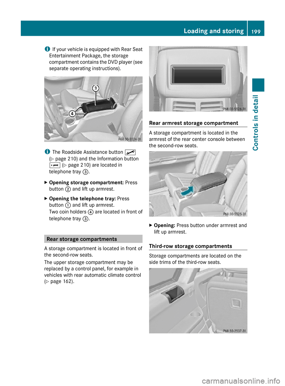
The Roadside Assistance button º
(Y page 210) and the Information button
E (Y page 210) are located in
telephone tray =.
X Opening storage compartment: Press
button ; and lift up armrest.
X Opening the telephone tray: Press
button : and lift up armrest.
Two coin holders ? are located in front of
telephone tray =. Rear storage compartments
A storage compartment is located in front of
the second-row seats.
The upper storage compartment may be
replaced by a control panel, for example in
vehicles with rear automatic climate control
(Y page 162). Rear armrest storage compartment
A storage compartment is located in the
armrest of the rear center console between
the second-row seats.
X
Opening: Press button under armrest and
lift up armrest.
Third-row storage compartments Storage compartments are located on the
side trims of the third-row seats. Loading and storing
199Controls in detail
251_AKB; 4; 52, en-US
d2ureepe, Version: 2.11.8.1 2009-03-23T09:22:52+01:00 - Seite 199 Z
Page 202 of 364
i
If your vehicle is equipped with a 3-zone
automatic climate control, the storage
compartments are replaced by adjustable
air vents (Y page 164). Rear center console
The rear center console is located between
the second-row seats.
The rear center console contains a storage
compartment (Y page 199) and a cup holder
(Y page 203).
i When fully expanding the cargo
compartment, the rear center console has
to be removed from the vehicle in order for
the cargo compartment floor to be an even
plane ( Y page 190).
Removing G
Warning!
Remove all containers that may be stored in
the cup holder of the rear center console.
Otherwise liquids could spill on vehicle
occupants and/or vehicle equipment. Hot
liquids spilled on vehicle occupants may
cause serious personal injury. Liquids spilled
on vehicle equipment may cause damage not
covered by the Mercedes-Benz Limited
Warranty.
! To prevent damage to the rear center
console and/or its components, make sure
the storage compartment is closed before
removing the rear center console.
i Remove all items from the rear armrest
storage compartment (Y page 199) of the
rear center console to reduce its weight. X
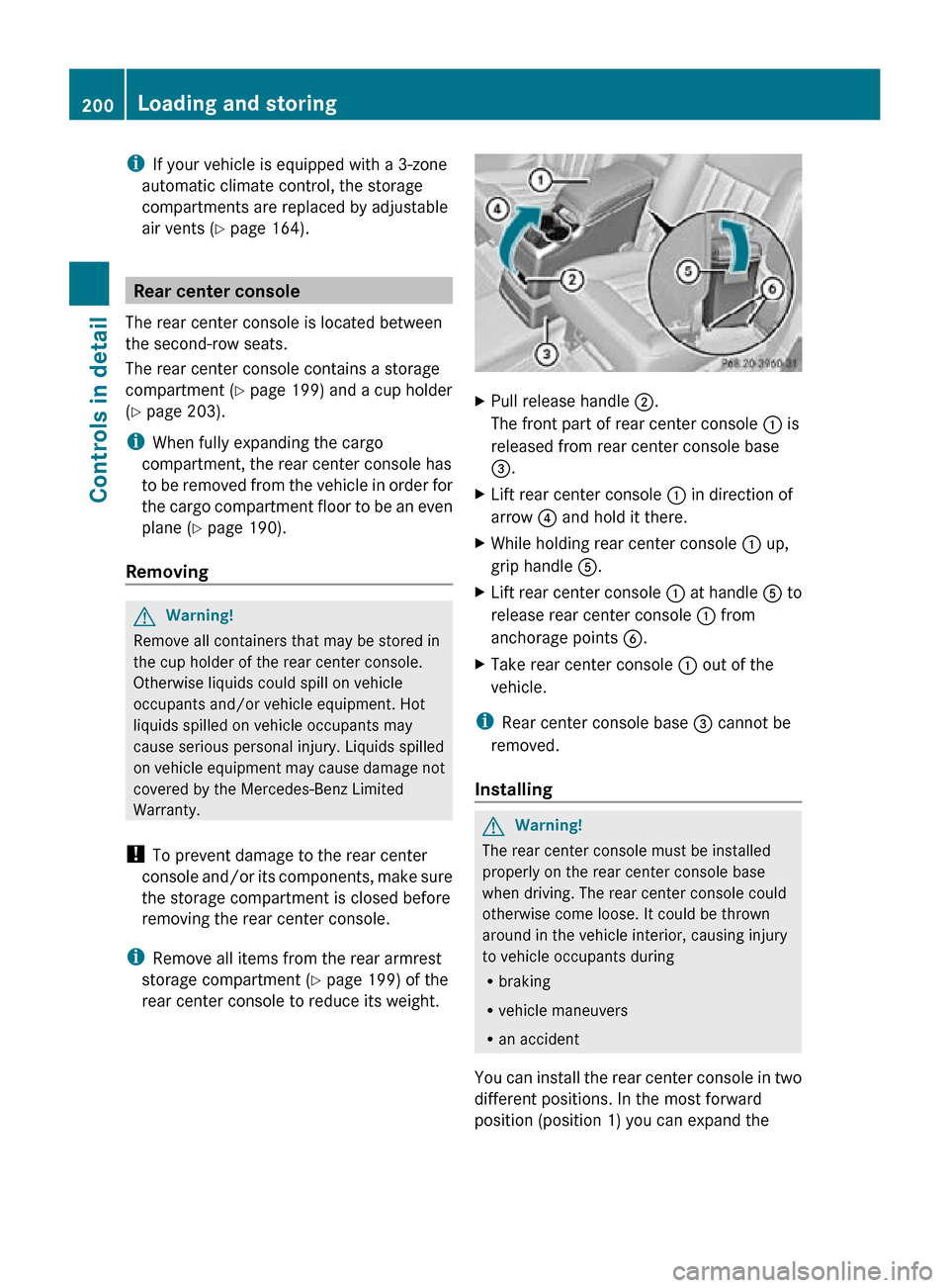
Pull release handle ;.
The front part of rear center console : is
released from rear center console base
=.
X Lift rear center console : in direction of
arrow ? and hold it there.
X While holding rear center console : up,
grip handle A.
X Lift rear center console : at handle A to
release rear center console : from
anchorage points B.
X Take rear center console : out of the
vehicle.
i Rear center console base = cannot be
removed.
Installing G
Warning!
The rear center console must be installed
properly on the rear center console base
when driving. The rear center console could
otherwise come loose. It could be thrown
around in the vehicle interior, causing injury
to vehicle occupants during
R braking
R vehicle maneuvers
R an accident
You can install the rear center console in two
different positions. In the most forward
position (position 1) you can expand the 200
Loading and storingControls in detail
251_AKB; 4; 52, en-US
d2ureepe,
Version: 2.11.8.1 2009-03-23T09:22:52+01:00 - Seite 200
Page 203 of 364
cargo compartment fully (
Y page 190)
without removing the rear center console.
i The storage compartment and the cup
holder in the rear center console are only
illuminated, when the rear center console
is installed in the most rearward position
(position 0). X
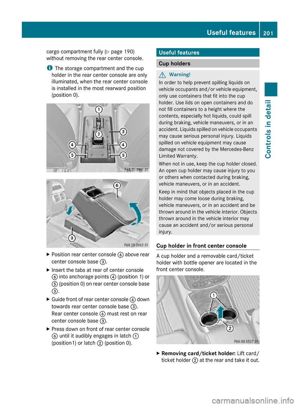
Position rear center console B above rear
center console base =.
X Insert the tabs at rear of center console
B into anchorage points ? (position 1) or
A (position 0) on rear center console base
=.
X Guide front of rear center console B down
towards rear center console base =.
Rear center console B must rest on rear
center console base =.
X Press down on front of rear center console
B until it audibly engages in latch :
(position1) or latch ; (position 0). Useful features
Cup holders
G
Warning!
In order to help prevent spilling liquids on
vehicle occupants and/or vehicle equipment,
only use containers that fit into the cup
holder. Use lids on open containers and do
not fill containers to a height where the
contents, especially hot liquids, could spill
during braking, vehicle maneuvers, or in an
accident. Liquids spilled on vehicle occupants
may cause serious personal injury. Liquids
spilled on vehicle equipment may cause
damage not covered by the Mercedes-Benz
Limited Warranty.
When not in use, keep the cup holder closed.
An open cup holder may cause injury to you
or others when contacted during braking,
vehicle maneuvers, or in an accident.
Keep in mind that objects placed in the cup
holder may come loose during braking,
vehicle maneuvers, or in an accident and be
thrown around in the vehicle interior. Objects
thrown around in the vehicle interior may
cause an accident and/or serious personal
injury.
Cup holder in front center console A cup holder and a removable card/ticket
holder with bottle opener are located in the
front center console.
X
Removing card/ticket holder: Lift card/
ticket holder ; at the rear and take it out. Useful features
201Controls in detail
251_AKB; 4; 52, en-US
d2ureepe, Version: 2.11.8.1 2009-03-23T09:22:52+01:00 - Seite 201 Z