2010 MERCEDES-BENZ ML63AMG spare wheel
[x] Cancel search: spare wheelPage 273 of 368

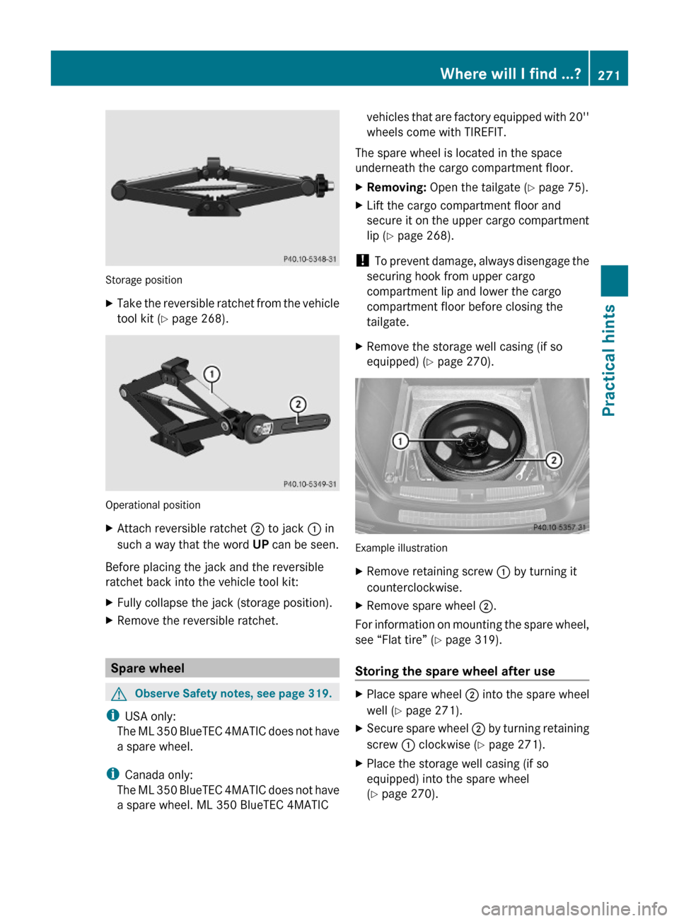
Storage position
XTake the reversible ratchet from the vehicle
tool kit (Y page 268).
Operational position
XAttach reversible ratchet ; to jack : in
such a way that the word UP can be seen.
Before placing the jack and the reversible
ratchet back into the vehicle tool kit:
XFully collapse the jack (storage position).XRemove the reversible ratchet.
Spare wheel
GObserve Safety notes, see page 319.
iUSA only:
The ML 350 BlueTEC 4MATIC does not have
a spare wheel.
iCanada only:
The ML 350 BlueTEC 4MATIC does not have
a spare wheel. ML 350 BlueTEC 4MATIC
vehicles that are factory equipped with 20''
wheels come with TIREFIT.
The spare wheel is located in the space
underneath the cargo compartment floor.
XRemoving: Open the tailgate (Y page 75).XLift the cargo compartment floor and
secure it on the upper cargo compartment
lip (Y page 268).
! To prevent damage, always disengage the
securing hook from upper cargo
compartment lip and lower the cargo
compartment floor before closing the
tailgate.
XRemove the storage well casing (if so
equipped) (Y page 270).
Example illustration
XRemove retaining screw : by turning it
counterclockwise.
XRemove spare wheel ;.
For information on mounting the spare wheel,
see “Flat tire” (Y page 319).
Storing the spare wheel after use
XPlace spare wheel ; into the spare wheel
well (Y page 271).
XSecure spare wheel ; by turning retaining
screw : clockwise (Y page 271).
XPlace the storage well casing (if so
equipped) into the spare wheel
(Y page 270).
Where will I find ...?271Practical hints164_AKB; 7; 31, en-USd2ureepe,Version: 2.11.8.12009-09-11T12:07:36+02:00 - Seite 271Z
Page 284 of 368

Display messagesPossible causes/consequences and M SolutionsTire
Pressure
MonitorWheel
Sensor
MissingAt least one sensor is defect (e.g. battery is empty).
The respective tire is indicated by – – instead of the tire
inflation pressure in the multifunction display.XHave the Advanced TPMS checked at an authorized
Mercedes-Benz Center.XHave the wheel sensors installed at an authorized
Mercedes-Benz Center.At least one wheel without appropriate wheel sensors is
mounted (e.g. spare tire).
The respective tire is indicated by – – instead of the tire
inflation pressure in the multifunction display.XHave the Advanced TPMS checked at an authorized
Mercedes-Benz Center.XHave the wheel sensors installed at an authorized
Mercedes-Benz Center.Tire
Pressure
MonitorCurrently
Unavailabl
eThe Advanced TPMS cannot monitor the tire inflation pressure
due to a nearby radio interference source or insufficient
power supply.
As soon as the causes of the malfunction have been rectified,
the Advanced TPMS becomes active again automatically after
a few minutes of driving.Tire
Pressure(s
) Please
CorrectThe tire inflation pressure is too low in at least one tire.
or
The tire inflation pressures of the individual tires differ from
each other significantly.
The tire inflation pressure values are shown in the
multifunction display.XCheck and correct tire inflation pressure as required
( Y page 221).XRestart the Advanced TMPS ( Y page 226).Caution:
Tire
DefectAt least one tire is deflating.
The respective tire is indicated in the multifunction display.XCarefully bring the vehicle to a halt, avoiding abrupt
steering and braking maneuvers.XIf necessary, change the wheel ( Y page 319).282Vehicle status messages in the multifunction displayPractical hints
164_AKB; 7; 31, en-USd2ureepe,Version: 2.11.8.12009-09-11T12:07:36+02:00 - Seite 282
Page 321 of 368

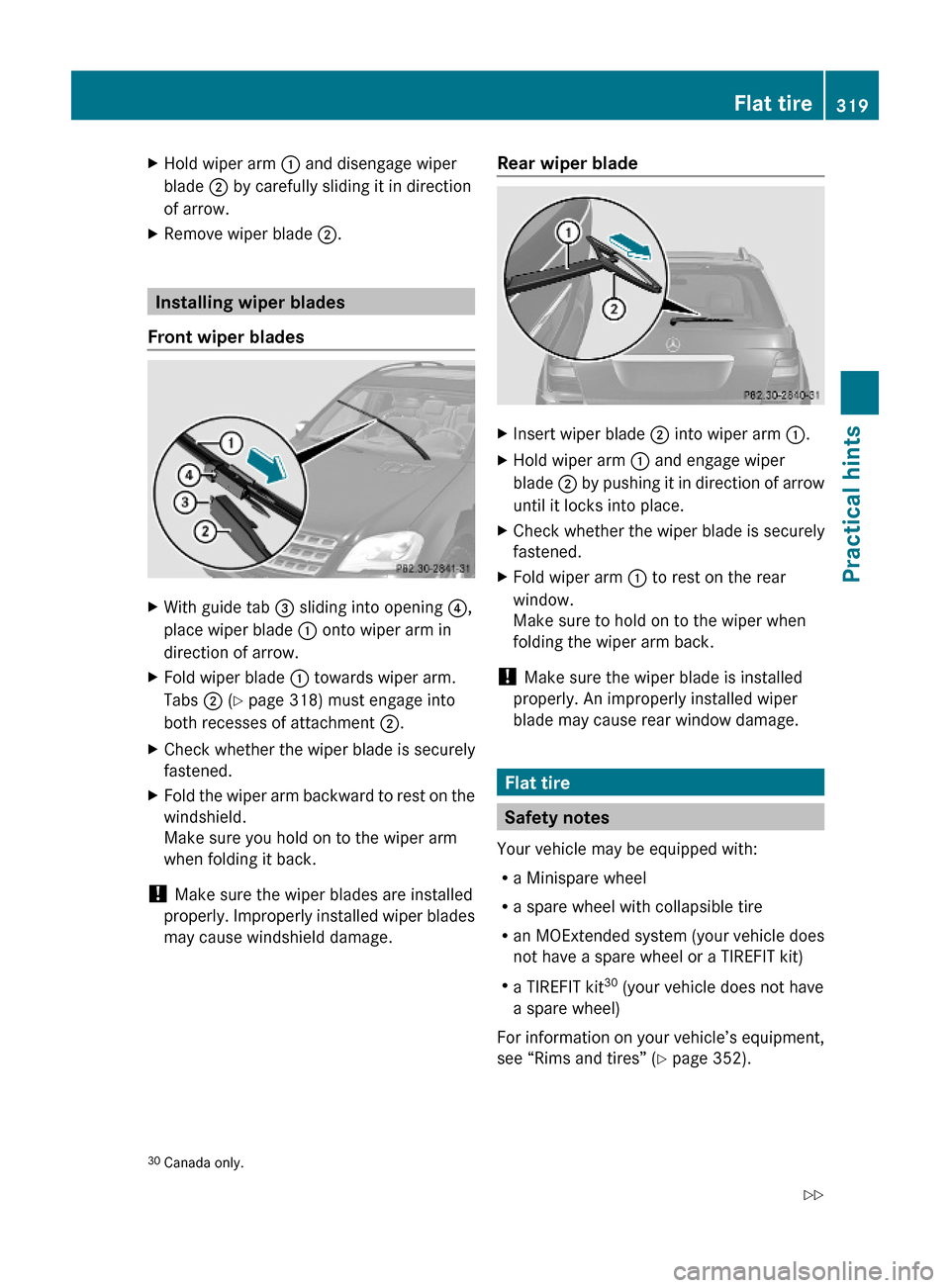
XHold wiper arm : and disengage wiper
blade ; by carefully sliding it in direction
of arrow.
XRemove wiper blade ;.
Installing wiper blades
Front wiper blades
XWith guide tab = sliding into opening ?,
place wiper blade : onto wiper arm in
direction of arrow.
XFold wiper blade : towards wiper arm.
Tabs ; (Y page 318) must engage into
both recesses of attachment ;.
XCheck whether the wiper blade is securely
fastened.
XFold the wiper arm backward to rest on the
windshield.
Make sure you hold on to the wiper arm
when folding it back.
! Make sure the wiper blades are installed
properly. Improperly installed wiper blades
may cause windshield damage.
Rear wiper bladeXInsert wiper blade ; into wiper arm :.XHold wiper arm : and engage wiper
blade ; by pushing it in direction of arrow
until it locks into place.
XCheck whether the wiper blade is securely
fastened.
XFold wiper arm : to rest on the rear
window.
Make sure to hold on to the wiper when
folding the wiper arm back.
! Make sure the wiper blade is installed
properly. An improperly installed wiper
blade may cause rear window damage.
Flat tire
Safety notes
Your vehicle may be equipped with:
Ra Minispare wheel
Ra spare wheel with collapsible tire
Ran MOExtended system (your vehicle does
not have a spare wheel or a TIREFIT kit)
Ra TIREFIT kit30 (your vehicle does not have
a spare wheel)
For information on your vehicle’s equipment,
see “Rims and tires” (Y page 352).
30Canada only.Flat tire319Practical hints164_AKB; 7; 31, en-USd2ureepe,Version: 2.11.8.12009-09-11T12:07:36+02:00 - Seite 319Z
Page 322 of 368

GWarning!
The dimensions of the spare wheel are
different from those of the road wheels. As a
result, the vehicle handling characteristics
change when driving with a spare wheel
mounted. Adapt your driving style
accordingly.
The spare wheel is for temporary use only.
When driving with a spare wheel mounted,
ensure proper tire inflation pressure and do
not exceed a vehicle speed of 50 mph
(80 km/h).
Contact the nearest authorized Mercedes-
Benz Center as soon as possible to have the
spare wheel replaced with a regular road
wheel.
Never operate the vehicle with more than one
spare wheel mounted.
Do not switch off the ESP ®
when a spare
wheel is mounted.
GWarning!
Vehicles with air suspension program:
Do not open or close any doors or the tailgate
while mounting a spare wheel. The vehicle
could rise or lower to a previously selected
level. You or others could be injured as a
result.
Preparing the vehicle
XVehicles with air suspension program:
Make sure the vehicle level is set to
highway level ( Y page 155).XWhenever possible, park the vehicle in a
safe distance from moving traffic on a hard,
flat surface.XTurn on the hazard warning flasher.XTurn the steering wheel so that the front
wheels are in a straight-ahead position.XEngage the parking brake.XShift the automatic transmission into park
position P.XTurn off the engine.XRemove the SmartKey from the starter
switch.
or
XVehicles with KEYLESS-GO: Open the
driver’s door (this puts the starter switch in
position 0, same as with the SmartKey
removed from the starter switch). The
driver’s door can then be closed again.
Open doors only when conditions are safe
to do so.XVehicles with KEYLESS-GO: Remove the
KEYLESS-GO start/stop button from the
starter switch.XHave any passenger exit the vehicle at a
safe distance from the roadway. Open
doors only when conditions are safe to do
so.
i Vehicles with spare wheel with collapsible
tire or TIREFIT:
Only use the power outlet in the second-
row footwell for electric air pump
operation.
You can use the power outlet even when
the ignition is switched off, e.g. in order to
inflate the collapsible tire.
An emergency shut-off feature is designed
to prevent the vehicle’s on-board voltage
from dropping below a minimum level. If
the on-board voltage drops to this
minimum level, the power outlets are
switched off automatically to help preserve
engine starting power.
Sealing tires with TIREFIT
Small tire punctures, particularly those in the
tread, can be sealed with TIREFIT.
TIREFIT can be used in ambient temperatures
down to -4‡ (-20†).
GWarning!
TIREFIT is a limited repair device. TIREFIT
cannot be used for cuts or punctures larger
than approximately 0.16 in (4 mm) and tire
320Flat tirePractical hints
164_AKB; 7; 31, en-USd2ureepe,Version: 2.11.8.12009-09-11T12:07:36+02:00 - Seite 320
Page 326 of 368

If the tire inflation pressure is at least 20 psi
(1.3 bar), inflate or deflate the tire to the
correct tire inflation pressure (see Tire and
Loading Information placard on the driver’s
door B-pillar):XTo increase tire inflation pressure:
Switch on the electric air pump.XTo decrease tire inflation pressure:
Version 1: Open vent screw F on
pressure gauge G (Y page 322).
Version 2: Press deflate button F located
at the end of the filler hose.XDrive to the nearest qualified workshop,
e.g. an authorized Mercedes-Benz Center,
to have the damaged tire replaced.XRecommended duration of use: A
maximum of 300 miles (500 km) at 50 mph
( 80 km/h) or below with the recommended
tire inflation pressure.XContact an authorized Mercedes-Benz
Center as soon as possible to obtain a new
TIREFIT kit.XBring used TIREFIT materials to an
authorized Mercedes-Benz Center for
proper disposal.XReplace your TIREFIT container every
4 years. Replacement containers are
available at any authorized Mercedes-Benz
Center.
Mounting the spare wheel
Introduction
XPrepare the vehicle as described
( Y page 320).XTake the following out of the vehicle:
R spare wheel
R jack
R wheel wrench
R collapsible wheel chockR
alignment bolt
R electric air pump (required for vehicles
with spare wheel with collapsible tire
only)
For information on where to find the
respective items, see “Where will I find ...?”
( Y page 268) and ( Y page 271).
i Vehicles without spare wheel are not
factory-equipped with the tools required for
a wheel change such as a jack or a wheel
wrench. Some tools required for a wheel
change are specific to your vehicle.
Contact an authorized Mercedes-Benz
Center to obtain the tools approved for
your vehicle. This section describes the
wheel change using the tools approved and
recommended for your vehicle.
Lifting the vehicle
GWarning!
When jacking up the vehicle, only use the jack
which has been specifically approved by
Mercedes-Benz for your vehicle.
The jack is designed exclusively for jacking up
the vehicle at the jack take-up brackets built
into both sides of the vehicle. Make sure the
jack arm is fully seated in the jack take-up
bracket. The jack must always be vertical
when in use, especially on inclines or
declines.
The jack is intended only for lifting the vehicle
briefly for wheel changes. It is not suited for
performing maintenance work under the
vehicle. To help avoid personal injury, use the
jack only to lift the vehicle during a wheel
change.
Never get beneath the vehicle while it is
supported by the jack. Keep hands and feet
away from the area under the lifted vehicle.
Always lower the vehicle onto sufficient
capacity jackstands before working under the
vehicle.
Always engage the parking brake firmly and
block the wheels with wheel chocks or other
324Flat tirePractical hints
164_AKB; 7; 31, en-USd2ureepe,Version: 2.11.8.12009-09-11T12:07:36+02:00 - Seite 324
Page 329 of 368

Removing the wheelXUnscrew the uppermost wheel bolt and
remove it.
XReplace this wheel bolt with alignment
bolt :.
XRemove the remaining bolts.
! Do not place wheel bolts in sand or dirt.
This could result in damage to the wheel
bolts and wheel hub threads.
XRemove the wheel.
Attaching the spare wheel
GWarning!
Vehicles with spare wheel with collapsible tire
only: Inflate collapsible tire only after the
wheel is properly attached.
Inflate the collapsible tire using the electric
air pump before lowering the vehicle.
GWarning!
Always replace wheel bolts that are damaged
or rusted.
Never apply oil or grease to wheel bolts.
Damaged wheel hub threads should be
repaired immediately. Do not continue to
drive under these circumstances! Contact an
authorized Mercedes-Benz Center or call
Roadside Assistance.
Incorrect wheel bolts or improperly tightened
wheel bolts can cause the wheel to come off.
This could cause an accident. Make sure to
use the correct wheel bolts.
GWarning!
Only use genuine Mercedes-Benz wheel bolts.
Other wheel bolts may come loose.
Do not tighten the wheel bolts when the
vehicle is raised. Otherwise the vehicle could
fall off the jack.
Wheel bolt : must be used for 18", 19", 20"
and 21" light alloy wheels as well as the spare
wheel with collapsible tire. Wheel bolt ;
must be used for the Minispare wheel. The
wheel bolts for the Minispare wheel are
located in vehicle tool kit.
! Wheel bolts ; must be used when
mounting the Minispare wheel. The use of
any wheel bolts other than wheel bolts ;
for the Minispare wheel will damage the
vehicle’s brakes.
GWarning!
Make sure to use the original length wheel
bolts when remounting the original wheel
after it has been repaired.
XClean contact surfaces of wheel and wheel
hub.
! To avoid paint damage, place wheel flat
against hub and hold it there while
installing first wheel bolt.
Flat tire327Practical hints164_AKB; 7; 31, en-USd2ureepe,Version: 2.11.8.12009-09-11T12:07:36+02:00 - Seite 327Z
Page 330 of 368

XGuide the spare wheel onto the alignment
bolt and push it on.
XInsert the wheel bolts and tighten them
slightly.
XUnscrew the alignment bolt.XInstall the last wheel bolt and tighten it
slightly.
XVehicles with spare wheel with
collapsible tire: Continue the procedure
by following the instructions under
“Inflating the collapsible tire”
(Y page 328) and then “Lowering the
vehicle” (Y page 329).
or
XVehicles with Minispare wheel: Continue
the procedure by following the instructions
under “Lowering the vehicle”
(Y page 329).
Inflating the collapsible tire
GWarning!
Inflate collapsible tire only after the wheel is
properly attached.
Inflate the collapsible tire using the electric
air pump before lowering the vehicle.
GWarning!
Observe safety instructions on air pump label.
! Do not lower the vehicle before inflating
the collapsible tire. Otherwise the rim may
be damaged.
Your vehicle may be equipped with either of
two versions of the electric air pump:
RVersion 1: The air hose with pressure
gauge and the electrical plug are located
behind a flap.
RVersion 2: The pressure gauge is located
in the pump housing. The air hose and
electrical plug are located at the bottom of
the pump housing.
The following description applies to both
versions. Differences in usage are expressly
declared.
Version 1
Version 2
XVersion 1 only: Open flap : on electric
air pump.
XVersion 1 only: Pull out electrical plug
= and air hose with pressure gauge and
vent screw ?.
XVersion 2 only: Pull electrical plug = and
the air hose out of the pump housing
bottom.
328Flat tirePractical hints
164_AKB; 7; 31, en-USd2ureepe,Version: 2.11.8.12009-09-11T12:07:36+02:00 - Seite 328
Page 331 of 368

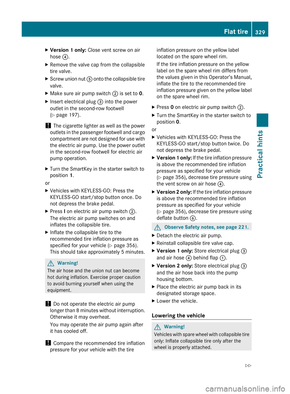
XVersion 1 only: Close vent screw on air
hose ?.XRemove the valve cap from the collapsible
tire valve.XScrew union nut A onto the collapsible tire
valve.XMake sure air pump switch ; is set to 0.XInsert electrical plug = into the power
outlet in the second-row footwell
( Y page 197).
!
The cigarette lighter as well as the power
outlets in the passenger footwell and cargo
compartment are not designed for use with
the electric air pump. Use the power outlet
in the second-row footwell for electric air
pump operation.
XTurn the SmartKey in the starter switch to
position 1.
or
XVehicles with KEYLESS-GO: Press the
KEYLESS-GO start/stop button once. Do
not depress the brake pedal.XPress I on electric air pump switch ;.
The electric air pump switches on and
inflates the collapsible tire.XInflate the collapsible tire to the
recommended tire inflation pressure as
specified for your vehicle ( Y page 356).
This should take approximately 5 minutes.GWarning!
The air hose and the union nut can become
hot during inflation. Exercise proper caution
to avoid burning yourself when using the
equipment.
! Do not operate the electric air pump
longer than 8 minutes without interruption.
Otherwise it may overheat.
You may operate the air pump again after
it has cooled off.
! Compare the recommended tire inflation
pressure for your vehicle with the tire
inflation pressure on the yellow label
located on the spare wheel rim.
If the tire inflation pressure on the yellow
label on the spare wheel rim differs from
the values given in this Operator’s Manual,
inflate the tire to the recommended tire
inflation pressure given on the yellow label
on the spare wheel rim.XPress 0 on electric air pump switch ;.XTurn the SmartKey in the starter switch to
position 0.
or
XVehicles with KEYLESS-GO: Press the
KEYLESS-GO start/stop button twice. Do
not depress the brake pedal.XVersion 1 only: If the tire inflation pressure
is above the recommended tire inflation
pressure as specified for your vehicle
( Y page 356), decrease tire pressure using
the vent screw on air hose ?.XVersion 2 only: If the tire inflation pressure
is above the recommended tire inflation
pressure as specified for your vehicle
( Y page 356), decrease tire pressure using
deflate button B.GObserve Safety notes, see page 221.XDetach the electric air pump.XReinstall collapsible tire valve cap.XVersion 1 only: Store electrical plug =
and air hose ? behind flap :.XVersion 2 only: Store electrical plug =
and the air hose back into the pump
housing bottom.XPlace the electric air pump back in its
designated storage space.XLower the vehicle.
Lowering the vehicle
GWarning!
Vehicles with spare wheel with collapsible tire
only: Inflate collapsible tire only after the
wheel is properly attached.
Flat tire329Practical hints164_AKB; 7; 31, en-USd2ureepe,Version: 2.11.8.12009-09-11T12:07:36+02:00 - Seite 329Z