2010 MERCEDES-BENZ ML350 30 pin
[x] Cancel search: 30 pinPage 157 of 368

Reduce set speed:XBriefly press the cruise control lever down
past the resistance point in direction of
arrow ;.
XRelease the cruise control lever.
The vehicle speed decreases in increments
of 5 mph (Canada: 10 km/h).
Each time the set speed is changed, DSR
will appear in the multifunction display and
the changed set speed is shown.
The new speed is set and the vehicle will
accelerate or decelerate. Keep in mind that
it may take a brief moment until the vehicle
has reached the new set speed.
The set speed is canceled when the DSR is
switched off. If the DSR is switched on again,
the DSR will use the programmed default
speed (Y page 138).
Off-road driving program
The off-road driving program is designed to
assist the driver when driving off-road in
terrain and crossing water. The off-road
driving program adjusts the engine power and
shifting of the automatic transmission to be
more suitable for the off-road use of the
vehicle. In addition, the ABS, ESP®, and 4-ETS
designed for off-road use are automatically
activated.
In the following situations you should switch
to the off-road driving program:
Rduring off-road driving
Rwhen crossing water (Y page 251)
Rwhen towing up or down on steep gradients
Example illustration: All models, exceptML 63 AMG
iIn AMG vehicles you can switch the Off-
road driving program on or off via the
control system (Y page 125).
XSwitching on: Press switch :.
Indicator lamp ; comes on. The symbol
Ç appears in the lower multifunction
display.
XSwitching off: Press switch : again.
Indicator lamp ; goes out. The symbol
Ç disappears.
Air suspension program
The system lets you select the chassis and
suspension setup. The chassis and
suspension setup adjusts the damping
behavior and the ride height for your vehicle.
The system consists of two components. The
Adaptive Damping System (ADS)
(Y page 156) and the vehicle level control
(Y page 156).
Driving systems155Controls in detail164_AKB; 7; 31, en-USd2ureepe,Version: 2.11.8.12009-09-11T12:07:36+02:00 - Seite 155Z
Page 158 of 368

ML 63 AMG
The air suspension program is part of the ML
63 AMG standard equipment range.
Due to the vehicle’s sportier suspension
tuning, in comparison with standard vehicles,
the level positions in the ADS settings as well
as the speed thresholds for raising and
lowering the vehicle have been modified.
From the highway/high-speed level, the
vehicle is lowered to the ADS SPORT level
approximately 20 seconds after it is locked.
From the raised level, the vehicle is not
lowered after it is locked. When the engine is
started, the previously selected setting, e.g.
ADS COMF, is selected again.
! Be sure to observe this vehicle’s differing
values for ground clearance and vehicle
height in comparison to standard vehicles.
You could otherwise damage the vehicle.
Observe the values for
Ropening the tailgate
Rdriving off-road
Rthe vehicle’s main dimensions in the
“Technical data” section
Adaptive Damping System (ADS)
The Adaptive Damping System (ADS) is
controlled electronically and operates
continuously. It adjusts the damping
characteristics to the current operating and
driving conditions. The damping is adjusted
individually for each wheel. Driving safety and
tire comfort are increased.
The fine tuning of the damping is dependent
on:
Ryour driving style
Rroad surface conditions
Ryour personal settings
The following settings are available:
RAUTO (for normal driving situations)
Indicator lamps ; and = are off.
RSPORT (for sporty driving)
Indicator lamp ; comes on.
With the ADS SPORT setting, the vehicle is
lowered approximately 0.6 in (15 mm).
ML63 AMG:
With the ADS SPORT setting, the vehicle is
lowered approximately 0.3 in (8 mm).
RCOMF (for comfort driving)
Indicator lamp = comes on.
ML63 AMG:
The vehicle is raised approximately 0.28 in
(7 mm).
XStart the engine.XPress ADS switch : repeatedly until the
desired suspension tuning is reached.
The setting remains stored when you turn off
the engine.
Vehicle level control
Your vehicle automatically adjusts its ride
height to increase vehicle safety and to
reduce fuel consumption.
Changes to the vehicle level should be made
while the vehicle is moving. The vehicle will
then reach the set level as fast as possible.
When you park the vehicle and the ambient
temperature changes, the vehicle level may
change visibly. When the temperature drops,
156Driving systemsControls in detail
164_AKB; 7; 31, en-USd2ureepe,Version: 2.11.8.12009-09-11T12:07:36+02:00 - Seite 156
Page 162 of 368

GWarning!
If a drive wheel is spinning due to insufficient
traction:
RWhile driving off, apply as little throttle as
possible.
RWhile driving, ease up on the accelerator
pedal.
RAdapt your speed and driving style to the
prevailing road conditions.
Failure to observe these guidelines could
cause the vehicle to skid.
The 4MATIC cannot prevent accidents
resulting from excessive speed.
! Do not tow with one axle raised. Doing so
could damage the transfer case, which is
not covered by the Mercedes-Benz Limited
Warranty. All wheels must be on or off the
ground. Observe instructions for towing the
vehicle with all wheels on the ground.
! Only conduct operational or performance
tests on a two-axle dynamometer. If such
tests are necessary, contact an authorized
Mercedes-Benz Center. You could
otherwise seriously damage the brake
system and/or the transfer case which is
not covered by the Mercedes-Benz Limited
Warranty.
iIn winter operation, the maximum
effectiveness of the 4MATIC is only
achieved with winter tires (Y page 242) or
snow chains as required.
Parktronic system
The Parktronic system is an electronic
parking aid with ultrasonic sensors designed
to assist the driver during parking maneuvers.
The Parktronic system indicates the relative
distance between the vehicle and an obstacle
visually and audibly.
The Parktronic system is activated
automatically when
Ryou switch on the ignition
and
Ryou release the parking brake
and
Rthe automatic transmission is in drive
position D, reverse gear R, or neutral
position N
The Parktronic system deactivates at speeds
above approximately 11 mph (18 km/h). At
lower speeds, the Parktronic system
activates again.
The Parktronic system also deactivates when
you shift the automatic transmission into
park position P or engage the parking brake.
The Parktronic system monitors the
surroundings of your vehicle with six sensors
in the front bumper and four sensors in the
rear bumper.
To function properly, sensors : must be free
of dirt, ice, snow and slush. Clean
sensors : regularly. Be careful not to
scratch or damage sensors :, see “Cleaning
the driving systems sensors” (Y page 263).
GWarning!
The Parktronic is a supplemental system. It is
not intended to, nor does it replace, the need
for extreme care. The responsibility during
parking and other critical maneuvers always
remains with the driver.
160Driving systemsControls in detail
164_AKB; 7; 31, en-USd2ureepe,Version: 2.11.8.12009-09-11T12:07:36+02:00 - Seite 160
Page 187 of 368
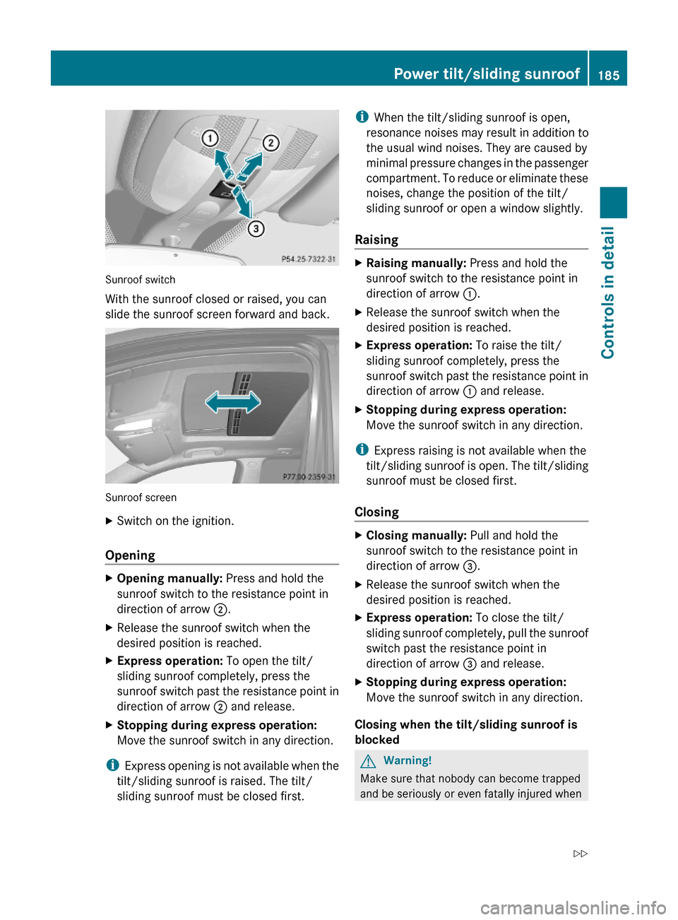
Sunroof switch
With the sunroof closed or raised, you can
slide the sunroof screen forward and back.
Sunroof screen
XSwitch on the ignition.
Opening
XOpening manually: Press and hold the
sunroof switch to the resistance point in
direction of arrow ;.
XRelease the sunroof switch when the
desired position is reached.
XExpress operation: To open the tilt/
sliding sunroof completely, press the
sunroof switch past the resistance point in
direction of arrow ; and release.
XStopping during express operation:
Move the sunroof switch in any direction.
iExpress opening is not available when the
tilt/sliding sunroof is raised. The tilt/
sliding sunroof must be closed first.
iWhen the tilt/sliding sunroof is open,
resonance noises may result in addition to
the usual wind noises. They are caused by
minimal pressure changes in the passenger
compartment. To reduce or eliminate these
noises, change the position of the tilt/
sliding sunroof or open a window slightly.
Raising
XRaising manually: Press and hold the
sunroof switch to the resistance point in
direction of arrow :.
XRelease the sunroof switch when the
desired position is reached.
XExpress operation: To raise the tilt/
sliding sunroof completely, press the
sunroof switch past the resistance point in
direction of arrow : and release.
XStopping during express operation:
Move the sunroof switch in any direction.
iExpress raising is not available when the
tilt/sliding sunroof is open. The tilt/sliding
sunroof must be closed first.
Closing
XClosing manually: Pull and hold the
sunroof switch to the resistance point in
direction of arrow =.
XRelease the sunroof switch when the
desired position is reached.
XExpress operation: To close the tilt/
sliding sunroof completely, pull the sunroof
switch past the resistance point in
direction of arrow = and release.
XStopping during express operation:
Move the sunroof switch in any direction.
Closing when the tilt/sliding sunroof is
blocked
GWarning!
Make sure that nobody can become trapped
and be seriously or even fatally injured when
Power tilt/sliding sunroof185Controls in detail164_AKB; 7; 31, en-USd2ureepe,Version: 2.11.8.12009-09-11T12:07:36+02:00 - Seite 185Z
Page 192 of 368

XLower the rear seat head restraints
completely (Y page 84).
XPull release handle =.
A red indicator A will be visible and seat
backrest ? is released.
XFold seat backrest ? forward.
Returning rear seat backrest to original
position
! Make sure that the seat belt is not
pinched when folding rear seat backrest.
XFold seat backrest : rearward until it
engages.
Red indicator A should no longer be
visible.
XFold seat cushion ; rearward until it locks
into position.
XCheck for secure locking by pushing and
pulling on seat backrest :.
GWarning!
If a red indicator is visible with the seat
backrest up, then the seat backrest is not
properly locked into position.
Always lock seat backrest in its upright
position when the rear seats are occupied, or
the extended cargo compartment is not in
use. Check for secure locking by pushing and
pulling on the seat backrest.
XAdjust the rear seat head restraints, if
necessary (Y page 83).
Cargo compartment cover blind
The cargo compartment cover blind can be
installed behind the rear seats.
! With the cargo compartment cover blind
installed, do not pile luggage higher than
the lower edges of the rear side windows.
190Loading and storingControls in detail
164_AKB; 7; 31, en-USd2ureepe,Version: 2.11.8.12009-09-11T12:07:36+02:00 - Seite 190
Page 199 of 368

XSwitch on the ignition.XPush in cigarette lighter :.
Cigarette lighter : will pop out
automatically when hot.
XTake out cigarette lighter :.XReinsert cigarette lighter : in its socket
after use.
! The lighter socket can be used to
accommodate 12V DC electrical
accessories (up to a maximum of 180 W)
designed for use with the standard
“cigarette lighter” plug type. Keep in mind,
however, that connecting accessories to
the lighter socket (for example extensive
connecting and disconnecting, or using
plugs that do not fit properly) can damage
the lighter socket. With the socket
damaged, the lighter may not function
properly any longer.
! The cigarette lighter is not designed for
use with the electric air pump. Use the
power outlet in the second-row footwell for
electric air pump operation.
Power outlets
iYou can use the power outlets even if the
ignition is switched off.
An emergency shut-off feature is designed
to prevent the vehicle’s on-board voltage
from dropping below a minimum level. If
the on-board voltage drops to this
minimum level, the power outlets are
automatically switched off, to help
preserve engine starting power.
12V Power outlets
! If you use all power outlets in the vehicle,
make sure that the maximum current
drawn does not exceed 55 A.
! The power outlets in the front passenger
footwell and cargo compartment are not
designed for use with the electric air pump.
Use the power outlet in the second-row
footwell for electric air pump operation.
The power outlets can be used to
accommodate 12V DC electrical accessories
(e.g. mobile phone chargers, auxiliary lamps)
up to a maximum of 20 A (240 W).
Front passenger footwell
Second-row footwell
Useful features197Controls in detail164_AKB; 7; 31, en-USd2ureepe,Version: 2.11.8.12009-09-11T12:07:36+02:00 - Seite 197Z
Page 207 of 368
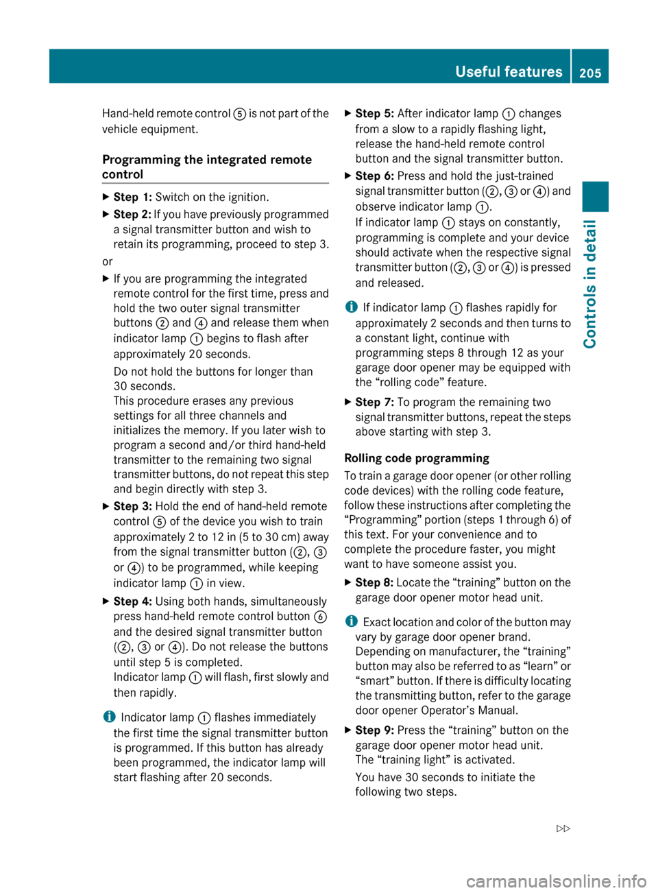
Hand-held remote control A is not part of the
vehicle equipment.
Programming the integrated remote
controlXStep 1: Switch on the ignition.XStep 2: If you have previously programmed
a signal transmitter button and wish to
retain its programming, proceed to step 3.
or
XIf you are programming the integrated
remote control for the first time, press and
hold the two outer signal transmitter
buttons ; and ? and release them when
indicator lamp : begins to flash after
approximately 20 seconds.
Do not hold the buttons for longer than
30 seconds.
This procedure erases any previous
settings for all three channels and
initializes the memory. If you later wish to
program a second and/or third hand-held
transmitter to the remaining two signal
transmitter buttons, do not repeat this step
and begin directly with step 3.XStep 3: Hold the end of hand-held remote
control A of the device you wish to train
approximately 2 to 12 in (5 to 30 cm) away
from the signal transmitter button ( ;, =
or ? ) to be programmed, while keeping
indicator lamp : in view.XStep 4: Using both hands, simultaneously
press hand-held remote control button B
and the desired signal transmitter button
( ; , = or ?). Do not release the buttons
until step 5 is completed.
Indicator lamp : will flash, first slowly and
then rapidly.
i Indicator lamp : flashes immediately
the first time the signal transmitter button
is programmed. If this button has already
been programmed, the indicator lamp will
start flashing after 20 seconds.
XStep 5: After indicator lamp : changes
from a slow to a rapidly flashing light,
release the hand-held remote control
button and the signal transmitter button.XStep 6: Press and hold the just-trained
signal transmitter button ( ;, = or ?) and
observe indicator lamp :.
If indicator lamp : stays on constantly,
programming is complete and your device
should activate when the respective signal
transmitter button ( ;, = or ?) is pressed
and released.
i If indicator lamp : flashes rapidly for
approximately 2 seconds and then turns to
a constant light, continue with
programming steps 8 through 12 as your
garage door opener may be equipped with
the “rolling code” feature.
XStep 7: To program the remaining two
signal transmitter buttons, repeat the steps
above starting with step 3.
Rolling code programming
To train a garage door opener (or other rolling
code devices) with the rolling code feature,
follow these instructions after completing the
“Programming” portion (steps 1 through 6) of
this text. For your convenience and to
complete the procedure faster, you might
want to have someone assist you.
XStep 8: Locate the “training” button on the
garage door opener motor head unit.
i Exact location and color of the button may
vary by garage door opener brand.
Depending on manufacturer, the “training”
button may also be referred to as “learn” or
“smart” button. If there is difficulty locating
the transmitting button, refer to the garage
door opener Operator’s Manual.
XStep 9: Press the “training” button on the
garage door opener motor head unit.
The “training light” is activated.
You have 30 seconds to initiate the
following two steps.Useful features205Controls in detail164_AKB; 7; 31, en-USd2ureepe,Version: 2.11.8.12009-09-11T12:07:36+02:00 - Seite 205Z
Page 210 of 368
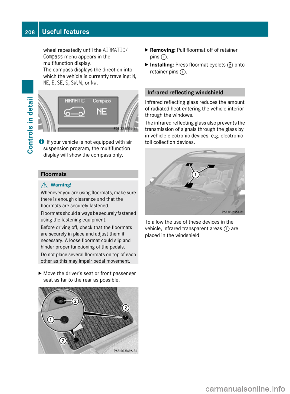
wheel repeatedly until the AIRMATIC/
Compass menu appears in the
multifunction display.
The compass displays the direction into
which the vehicle is currently traveling: N,
NE, E, SE, S, SW, W, or NW.
iIf your vehicle is not equipped with air
suspension program, the multifunction
display will show the compass only.
Floormats
GWarning!
Whenever you are using floormats, make sure
there is enough clearance and that the
floormats are securely fastened.
Floormats should always be securely fastened
using the fastening equipment.
Before driving off, check that the floormats
are securely in place and adjust them if
necessary. A loose floormat could slip and
hinder proper functioning of the pedals.
Do not place several floormats on top of each
other as this may impair pedal movement.
XMove the driver’s seat or front passenger
seat as far to the rear as possible.
XRemoving: Pull floormat off of retainer
pins :.
XInstalling: Press floormat eyelets ; onto
retainer pins :.
Infrared reflecting windshield
Infrared reflecting glass reduces the amount
of radiated heat entering the vehicle interior
through the windows.
The infrared reflecting glass also prevents the
transmission of signals through the glass by
in-vehicle electronic devices, e.g. electronic
toll collection devices.
To allow the use of these devices in the
vehicle, infrared transparent areas : are
placed in the windshield.
208Useful featuresControls in detail
164_AKB; 7; 31, en-USd2ureepe,Version: 2.11.8.12009-09-11T12:07:36+02:00 - Seite 208