2010 MERCEDES-BENZ GLK350 4MATIC Sport
[x] Cancel search: SportPage 193 of 344
Cargo net (Canada only)GWarning!
Make sure the cargo net is properly engaged
at top and bottom position and the tightening
belts are securely fastened.
Never use a damaged cargo net.
Always use cargo net when transporting
cargo. This helps to avoid personal injury from
smaller objects being thrown around in the
occupant compartment during a collision or
sudden maneuver.
The cargo net cannot prevent the movement
of large, heavier objects into the passenger
compartment in an accident. Such items must
be properly secured using the cargo tie-down
rings in the cargo compartment floor.
Passenger use of seats behind installed cargo
net is restricted because of the footwell being
taken up by the net.
Use of the cargo net is a particularly
important safety factor when the vehicle is
loaded higher than the top of the seat
backrests with smaller objects. For your
safety, always use the cargo net when
transporting cargo.
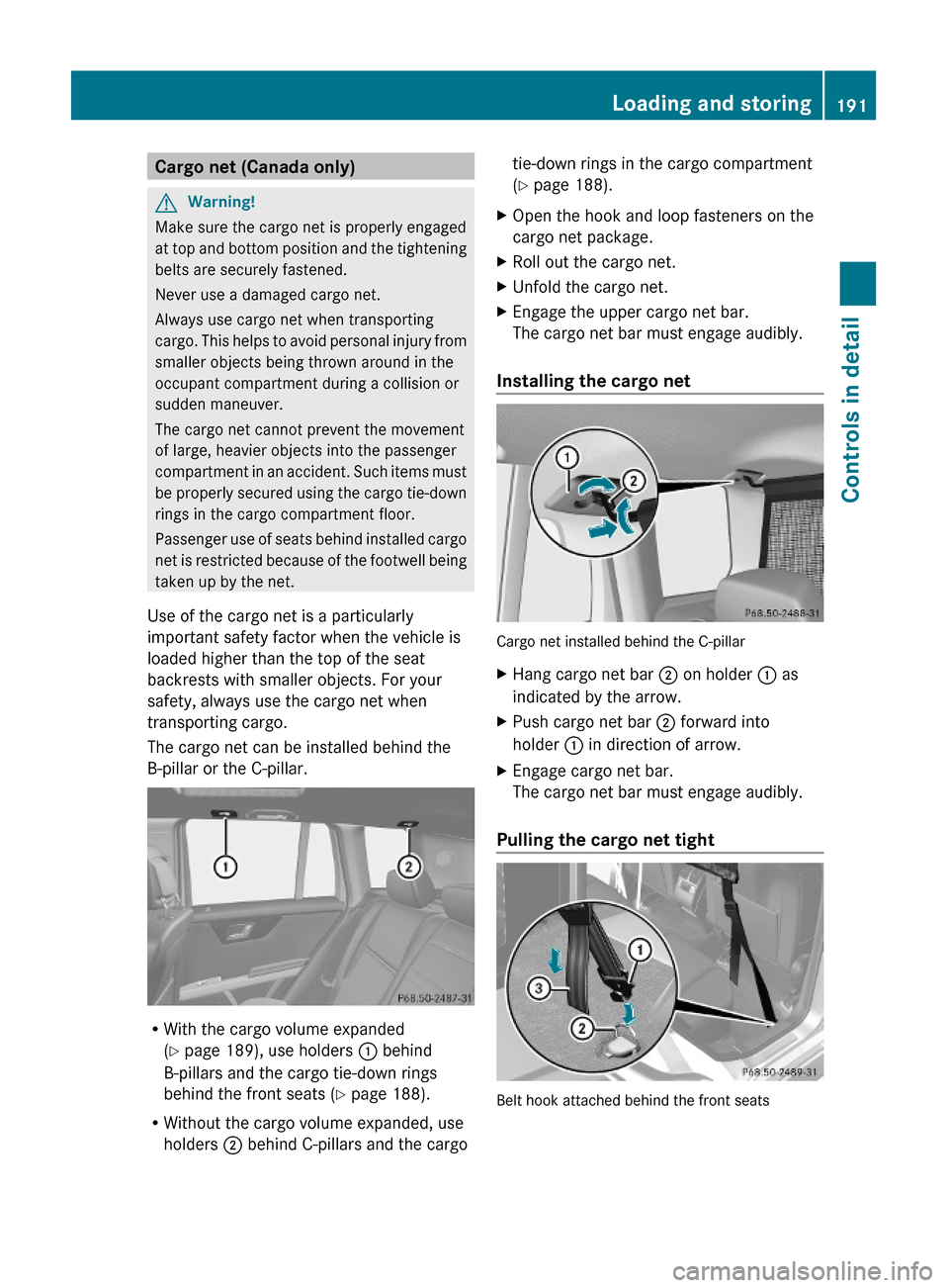
The cargo net can be installed behind the
B-pillar or the C-pillar.
RWith the cargo volume expanded
(Y page 189), use holders : behind
B-pillars and the cargo tie-down rings
behind the front seats (Y page 188).
RWithout the cargo volume expanded, use
holders ; behind C-pillars and the cargo
tie-down rings in the cargo compartment
(Y page 188).
XOpen the hook and loop fasteners on the
cargo net package.
XRoll out the cargo net.XUnfold the cargo net.XEngage the upper cargo net bar.
The cargo net bar must engage audibly.
Installing the cargo net
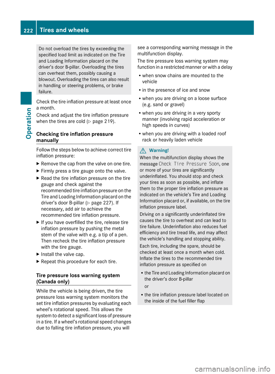
Cargo net installed behind the C-pillar
XHang cargo net bar ; on holder : as
indicated by the arrow.
XPush cargo net bar ; forward into
holder : in direction of arrow.
XEngage cargo net bar.
The cargo net bar must engage audibly.
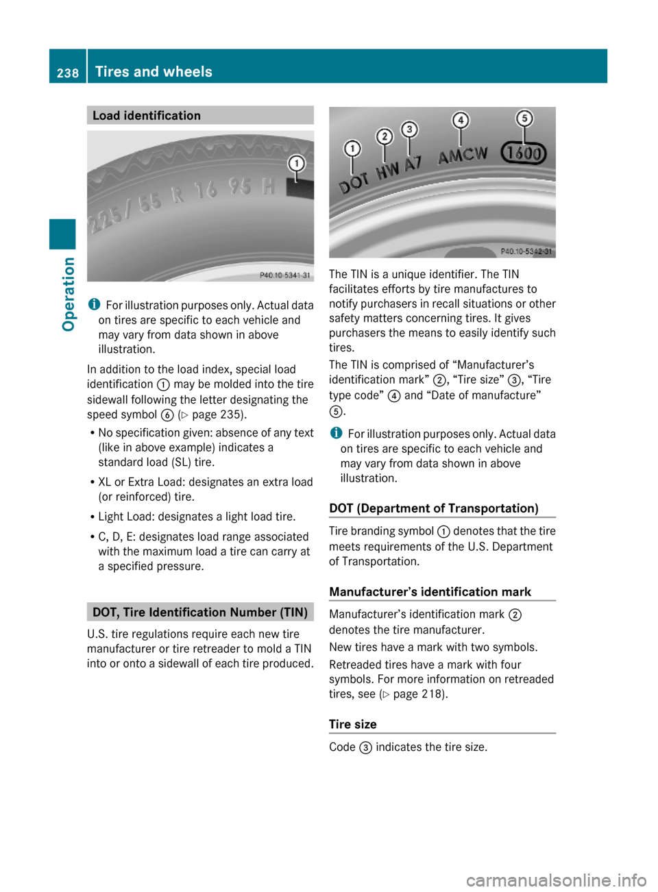
Pulling the cargo net tight
Belt hook attached behind the front seats
Loading and storing191Controls in detailX204_AKB; 3; 23, en-USd2ureepe,Version: 2.11.8.12009-07-16T19:16:58+02:00 - Seite 191Z
Page 224 of 344
Do not overload the tires by exceeding the
specified load limit as indicated on the Tire
and Loading Information placard on the
driver’s door B-pillar. Overloading the tires
can overheat them, possibly causing a
blowout. Overloading the tires can also result
in handling or steering problems, or brake
failure.
Check the tire inflation pressure at least once
a month.
Check and adjust the tire inflation pressure
when the tires are cold ( Y page 219).
Checking tire inflation pressure
manually
Follow the steps below to achieve correct tire
inflation pressure:
XRemove the cap from the valve on one tire.XFirmly press a tire gauge onto the valve.XRead the tire inflation pressure on the tire
gauge and check against the
recommended tire inflation pressure on the
Tire and Loading Information placard on the
driver’s door B-pillar ( Y page 227). If
necessary, add air to achieve the
recommended tire inflation pressure.XIf you have overfilled the tire, release tire
inflation pressure by pushing the metal
stem of the valve with e.g. a tip of a pen.
Then recheck the tire inflation pressure
with the tire gauge.XInstall the valve cap.XRepeat this procedure for each tire.
Tire pressure loss warning system
(Canada only)
While the vehicle is being driven, the tire
pressure loss warning system monitors the
set tire inflation pressures by evaluating each
wheel’s rotational speed. This allows the
system to detect a significant loss of pressure
in a tire. If a wheel’s rotational speed changes
due to falling tire inflation pressure, you will
see a corresponding warning message in the
multifunction display.
The tire pressure loss warning system may
function in a restricted manner or with a delay
R when snow chains are mounted to the
vehicle
R in the presence of ice and snow
R when you are driving on a loose surface
(e.g. sand or gravel)
R when you are driving in a very sporty
manner (involving rapid acceleration or
high speeds in curves)
R when you are driving with a loaded roof
rack or heavily laden vehicleGWarning!
When the multifunction display shows the
message Check Tire Pressure Soon , one
or more of your tires are significantly
underinflated. You should stop and check
your tires as soon as possible, and inflate
them to the proper tire inflation pressure as
indicated on the vehicle’s Tire and Loading
Information placard or, if available, on the tire
inflation pressure label.
Driving on a significantly underinflated tire
causes the tire to overheat and can lead to
tire failure. Underinflation also reduces fuel
efficiency and tire tread life, and may affect
the vehicle’s handling and stopping ability.
Each tire, including the spare, should be
checked at least once a month when cold.
Inflate the tires to the recommended tire
inflation pressure as specified on
R the Tire and Loading Information placard on
the driver’s door B-pillar
or
R the tire inflation pressure label located on
the inside of the fuel filler flap
222Tires and wheelsOperation
X204_AKB; 3; 23, en-USd2ureepe,Version: 2.11.8.12009-07-16T19:16:58+02:00 - Seite 222
Page 240 of 344
Load identification
iFor illustration purposes only. Actual data
on tires are specific to each vehicle and
may vary from data shown in above
illustration.
In addition to the load index, special load
identification : may be molded into the tire
sidewall following the letter designating the
speed symbol B (Y page 235).
RNo specification given: absence of any text
(like in above example) indicates a
standard load (SL) tire.
RXL or Extra Load: designates an extra load
(or reinforced) tire.
RLight Load: designates a light load tire.
RC, D, E: designates load range associated
with the maximum load a tire can carry at
a specified pressure.
DOT, Tire Identification Number (TIN)
U.S. tire regulations require each new tire
manufacturer or tire retreader to mold a TIN
into or onto a sidewall of each tire produced.
The TIN is a unique identifier. The TIN
facilitates efforts by tire manufactures to
notify purchasers in recall situations or other
safety matters concerning tires. It gives
purchasers the means to easily identify such
tires.
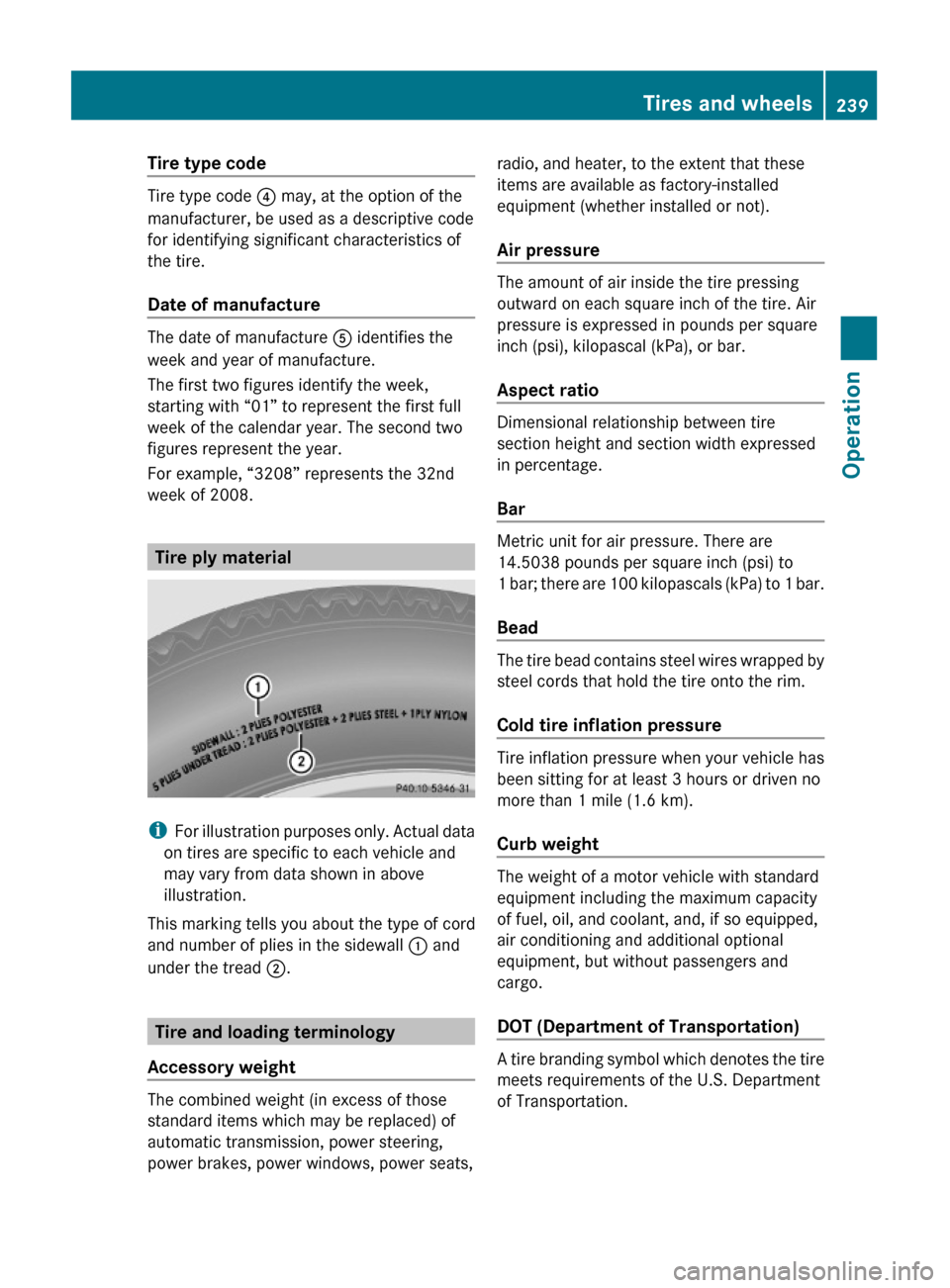
The TIN is comprised of “Manufacturer’s
identification mark” ;, “Tire size” =, “Tire
type code” ? and “Date of manufacture”
A.
iFor illustration purposes only. Actual data
on tires are specific to each vehicle and
may vary from data shown in above
illustration.
DOT (Department of Transportation)
Tire branding symbol : denotes that the tire
meets requirements of the U.S. Department
of Transportation.
Manufacturer’s identification mark
Manufacturer’s identification mark ;
denotes the tire manufacturer.
New tires have a mark with two symbols.
Retreaded tires have a mark with four
symbols. For more information on retreaded
tires, see (Y page 218).
Tire size
Code = indicates the tire size.
238Tires and wheelsOperation
X204_AKB; 3; 23, en-USd2ureepe,Version: 2.11.8.12009-07-16T19:16:58+02:00 - Seite 238
Page 241 of 344
Tire type code
Tire type code ? may, at the option of the
manufacturer, be used as a descriptive code
for identifying significant characteristics of
the tire.
Date of manufacture
The date of manufacture A identifies the
week and year of manufacture.
The first two figures identify the week,
starting with “01” to represent the first full
week of the calendar year. The second two
figures represent the year.
For example, “3208” represents the 32nd
week of 2008.
Tire ply material
iFor illustration purposes only. Actual data
on tires are specific to each vehicle and
may vary from data shown in above
illustration.
This marking tells you about the type of cord
and number of plies in the sidewall : and
under the tread ;.
Tire and loading terminology
Accessory weight
The combined weight (in excess of those
standard items which may be replaced) of
automatic transmission, power steering,
power brakes, power windows, power seats,
radio, and heater, to the extent that these
items are available as factory-installed
equipment (whether installed or not).
Air pressure
The amount of air inside the tire pressing
outward on each square inch of the tire. Air
pressure is expressed in pounds per square
inch (psi), kilopascal (kPa), or bar.
Aspect ratio
Dimensional relationship between tire
section height and section width expressed
in percentage.
Bar
Metric unit for air pressure. There are
14.5038 pounds per square inch (psi) to
1 bar; there are 100 kilopascals (kPa) to 1 bar.
Bead
The tire bead contains steel wires wrapped by
steel cords that hold the tire onto the rim.
Cold tire inflation pressure
Tire inflation pressure when your vehicle has
been sitting for at least 3 hours or driven no
more than 1 mile (1.6 km).
Curb weight
The weight of a motor vehicle with standard
equipment including the maximum capacity
of fuel, oil, and coolant, and, if so equipped,
air conditioning and additional optional
equipment, but without passengers and
cargo.
DOT (Department of Transportation)
A tire branding symbol which denotes the tire
meets requirements of the U.S. Department
of Transportation.
Tires and wheels239OperationX204_AKB; 3; 23, en-USd2ureepe,Version: 2.11.8.12009-07-16T19:16:58+02:00 - Seite 239Z
Page 300 of 344
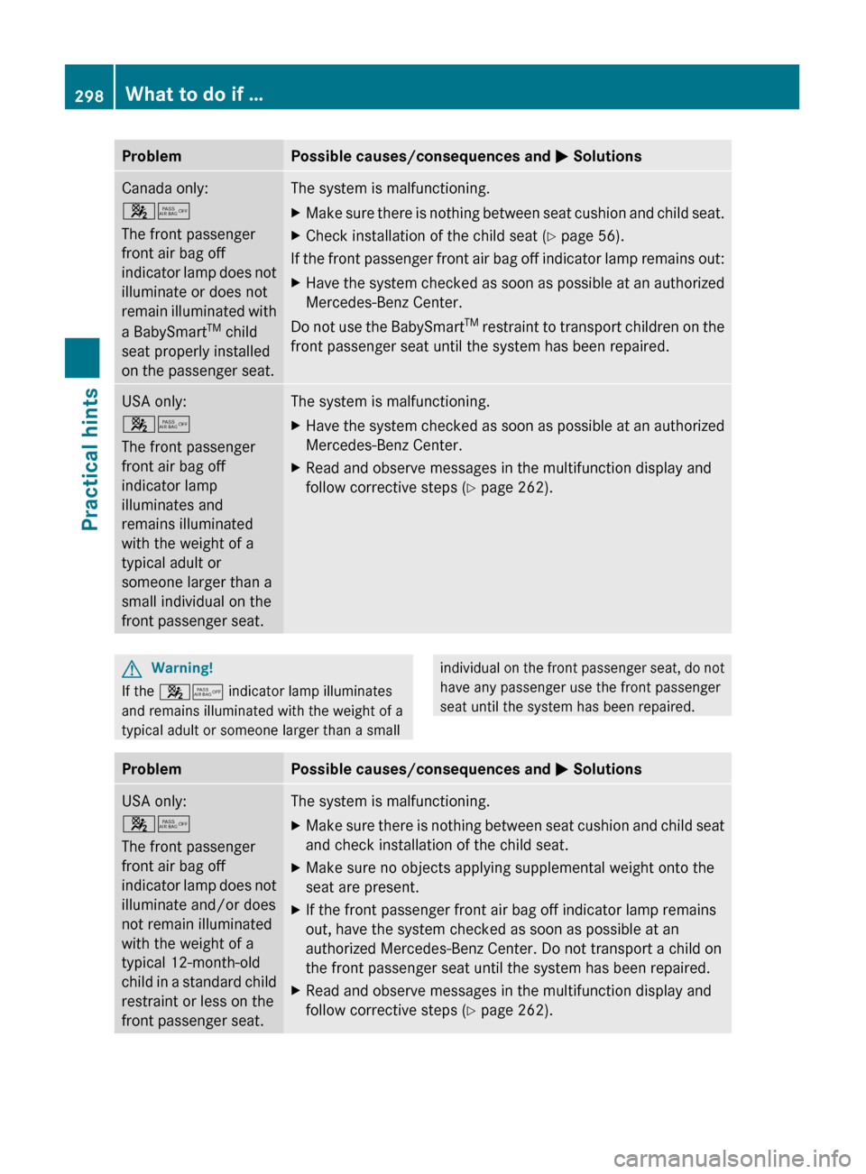
ProblemPossible causes/consequences and M SolutionsCanada only:
45
The front passenger
front air bag off
indicator lamp does not
illuminate or does not
remain illuminated with
a BabySmart TM
child
seat properly installed
on the passenger seat.The system is malfunctioning.XMake sure there is nothing between seat cushion and child seat.XCheck installation of the child seat ( Y page 56).
If the front passenger front air bag off indicator lamp remains out:
XHave the system checked as soon as possible at an authorized
Mercedes-Benz Center.
Do not use the BabySmart TM
restraint to transport children on the
front passenger seat until the system has been repaired.
USA only:
45
The front passenger
front air bag off
indicator lamp
illuminates and
remains illuminated
with the weight of a
typical adult or
someone larger than a
small individual on the
front passenger seat.The system is malfunctioning.XHave the system checked as soon as possible at an authorized
Mercedes-Benz Center.XRead and observe messages in the multifunction display and
follow corrective steps ( Y page 262).GWarning!
If the 45 indicator lamp illuminates
and remains illuminated with the weight of a
typical adult or someone larger than a small
individual on the front passenger seat, do not
have any passenger use the front passenger
seat until the system has been repaired.ProblemPossible causes/consequences and M SolutionsUSA only:
45
The front passenger
front air bag off
indicator lamp does not
illuminate and/or does
not remain illuminated
with the weight of a
typical 12-month-old
child in a standard child
restraint or less on the
front passenger seat.The system is malfunctioning.XMake sure there is nothing between seat cushion and child seat
and check installation of the child seat.XMake sure no objects applying supplemental weight onto the
seat are present.XIf the front passenger front air bag off indicator lamp remains
out, have the system checked as soon as possible at an
authorized Mercedes-Benz Center. Do not transport a child on
the front passenger seat until the system has been repaired.XRead and observe messages in the multifunction display and
follow corrective steps ( Y page 262).298What to do if …Practical hints
X204_AKB; 3; 23, en-USd2ureepe,Version: 2.11.8.12009-07-16T19:16:58+02:00 - Seite 298
Page 301 of 344
GWarning!
If the 45 indicator lamp does not
illuminate or remains out with the weight of a
typical 12-month-old child in a standard child
restraint or less on the front passenger seat,
do not transport a child on the front
passenger seat until the system has been
repaired.
Unlocking/locking manually
Unlocking the vehicle
If you cannot unlock the vehicle with the
SmartKey or with KEYLESS-GO, unlock the
driver’s door using the mechanical key.
The anti-theft alarm system will trigger when
you
Runlock the driver’s door with the
mechanical key
and
Ropen the driver’s door
To cancel the alarm, insert the SmartKey into
the starter switch.
Removing the mechanical key
XMove locking tab : in the direction of
arrow.
XSlide mechanical key ; out of the housing.Unlocking the driver’s doorXInsert mechanical key ; into the driver’s
door lock.
XTurn mechanical key ; counterclockwise
to position 1.
XPull the door handle to open the driver’s
door.
XTurn mechanical key ; back and remove
it from the driver’s door lock.
Locking the vehicle
If you cannot lock the vehicle with the
SmartKey or with KEYLESS-GO, lock it as
follows:
XOpen the driver’s door.XClose the front passenger door, the rear
doors, and the tailgate.
XPress the central locking switch
(Y page 71).
The locking knobs of the front passenger
door and the rear doors move down.
XIf the vehicle battery is disconnected or
drained: Press down the locking knobs on
the front passenger door and the rear
doors.
XExit the vehicle.XClose the driver’s door.Unlocking/locking manually299Practical hintsX204_AKB; 3; 23, en-USd2ureepe,Version: 2.11.8.12009-07-16T19:16:58+02:00 - Seite 299Z
Page 319 of 344
XPress 0 on electric air pump switch ;.XTurn the SmartKey in the starter switch to
position 0.
or
XVehicles with KEYLESS-GO: Press the
KEYLESS-GO start/stop button twice. Do
not depress the brake pedal.
XVersion 1 only: If the tire inflation pressure
is above the recommended tire inflation
pressure as specified for your vehicle
(Y page 333), decrease tire pressure using
the vent screw on air hose ?.
XVersion 2 only: If the tire inflation pressure
is above the recommended tire inflation
pressure as specified for your vehicle
(Y page 333), decrease tire pressure using
deflate button B.
GObserve Safety notes, see page 221.XDetach the electric air pump.XReinstall collapsible tire valve cap.XVersion 1 only: Store electrical plug =
and air hose ? behind flap :.
XVersion 2 only: Store electrical plug =
and the air hose back into the pump
housing bottom.
XPlace the electric air pump back in its
designated storage space.
XLower the vehicle.
Lowering the vehicle
GWarning!
Inflate collapsible tire only after the wheel is
properly attached.
Inflate the collapsible tire using the electric
air pump before lowering the vehicle.
XAttach ratchet to vehicle jack so that the
word DOWN can be seen.
Lower the vehicle until the vehicle is resting
fully on its own weight:
XTurn ratchet in direction DOWN.XRemove the jack.XTighten the five wheel bolts evenly,
following the diagonal sequence illustrated
(: to A), until all bolts are tight. Observe
a tightening torque of 110 lb-ft (150 Nm).
GWarning!
Have the tightening torque checked after
changing a wheel. The wheels could come
loose if they are not tightened to a torque of
110 lb-ft (150 Nm).
XFully collapse the jack to storage position,
see (Y page 261).
XStore the jack and the other vehicle tools
in the designated storage space.
iThe damaged road wheel cannot be
stored in the spare wheel well under the
cargo compartment floor. It should be
transported in the cargo compartment
wrapped in a protective wrap.
iVehicles with TPMS:
Do not restart the tire inflation pressure
monitor until a full size wheel/tire with
functioning sensor has been placed back
into service on the vehicle.
Battery
Safety notes
A battery should always be sufficiently
charged in order to achieve its rated service
life. Refer to Maintenance Booklet for battery
maintenance intervals.
Battery317Practical hintsX204_AKB; 3; 23, en-USd2ureepe,Version: 2.11.8.12009-07-16T19:16:58+02:00 - Seite 317Z
Page 323 of 344
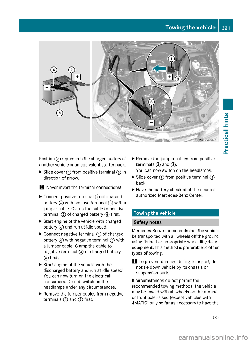
Position B represents the charged battery of
another vehicle or an equivalent starter pack.
XSlide cover : from positive terminal = in
direction of arrow.
! Never invert the terminal connections!
XConnect positive terminal ; of charged
battery B with positive terminal = with a
jumper cable. Clamp the cable to positive
terminal ; of charged battery B first.
XStart engine of the vehicle with charged
battery B and run at idle speed.
XConnect negative terminal ? of charged
battery B with negative terminal A with
a jumper cable. Clamp the cable to
negative terminal ? of charged battery
B first.
XStart engine of the vehicle with the
discharged battery and run at idle speed.
You can now turn on the electrical
consumers. Do not switch on the
headlamps under any circumstances.
XRemove the jumper cables from negative
terminals ? and A first.
XRemove the jumper cables from positive
terminals ; and =.
You can now switch on the headlamps.
XSlide cover : from positive terminal =
back.
XHave the battery checked at the nearest
authorized Mercedes-Benz Center.
Towing the vehicle
Safety notes
Mercedes-Benz recommends that the vehicle
be transported with all wheels off the ground
using flatbed or appropriate wheel lift/dolly
equipment. This method is preferable to other
types of towing.
! To prevent damage during transport, do
not tie down vehicle by its chassis or
suspension parts.
If circumstances do not permit the
recommended towing methods, the vehicle
may be towed with all wheels on the ground
or front axle raised (except vehicles with
4MATIC) only so far as necessary to have the
Towing the vehicle321Practical hintsX204_AKB; 3; 23, en-USd2ureepe,Version: 2.11.8.12009-07-16T19:16:58+02:00 - Seite 321Z