2010 MERCEDES-BENZ GL550 wheel
[x] Cancel search: wheelPage 345 of 380
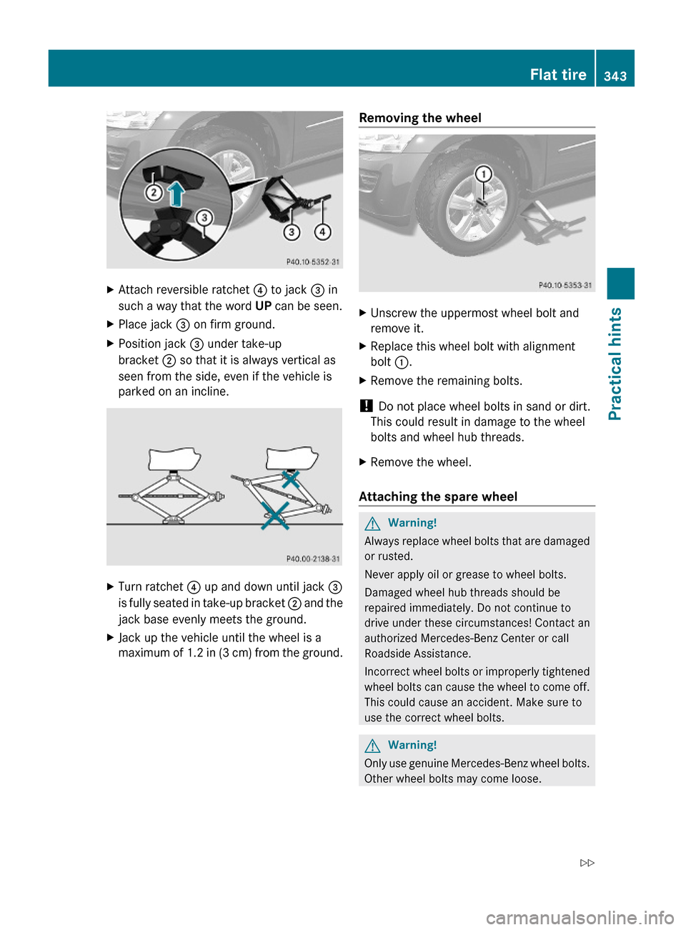
XAttach reversible ratchet ? to jack = in
such a way that the word UP can be seen.
XPlace jack = on firm ground.XPosition jack = under take-up
bracket ; so that it is always vertical as
seen from the side, even if the vehicle is
parked on an incline.
XTurn ratchet ? up and down until jack =
is fully seated in take-up bracket ; and the
jack base evenly meets the ground.
XJack up the vehicle until the wheel is a
maximum of 1.2 in (3 cm) from the ground.
Removing the wheelXUnscrew the uppermost wheel bolt and
remove it.
XReplace this wheel bolt with alignment
bolt :.
XRemove the remaining bolts.
! Do not place wheel bolts in sand or dirt.
This could result in damage to the wheel
bolts and wheel hub threads.
XRemove the wheel.
Attaching the spare wheel
GWarning!
Always replace wheel bolts that are damaged
or rusted.
Never apply oil or grease to wheel bolts.
Damaged wheel hub threads should be
repaired immediately. Do not continue to
drive under these circumstances! Contact an
authorized Mercedes-Benz Center or call
Roadside Assistance.
Incorrect wheel bolts or improperly tightened
wheel bolts can cause the wheel to come off.
This could cause an accident. Make sure to
use the correct wheel bolts.
GWarning!
Only use genuine Mercedes-Benz wheel bolts.
Other wheel bolts may come loose.
Flat tire343Practical hintsX164_AKB; 5; 31, en-USd2ureepe,Version: 2.11.8.12009-09-11T12:30:16+02:00 - Seite 343Z
Page 346 of 380
Do not tighten the wheel bolts when the
vehicle is raised. Otherwise the vehicle could
fall off the jack.
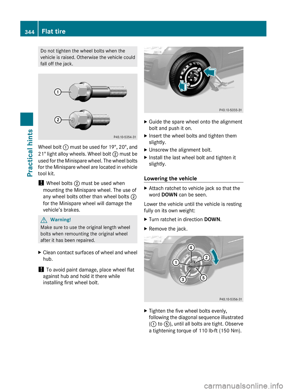
Wheel bolt : must be used for 19", 20", and
21" light alloy wheels. Wheel bolt ; must be
used for the Minispare wheel. The wheel bolts
for the Minispare wheel are located in vehicle
tool kit.
! Wheel bolts ; must be used when
mounting the Minispare wheel. The use of
any wheel bolts other than wheel bolts ;
for the Minispare wheel will damage the
vehicle’s brakes.
GWarning!
Make sure to use the original length wheel
bolts when remounting the original wheel
after it has been repaired.
XClean contact surfaces of wheel and wheel
hub.
! To avoid paint damage, place wheel flat
against hub and hold it there while
installing first wheel bolt.
XGuide the spare wheel onto the alignment
bolt and push it on.
XInsert the wheel bolts and tighten them
slightly.
XUnscrew the alignment bolt.XInstall the last wheel bolt and tighten it
slightly.
Lowering the vehicle
XAttach ratchet to vehicle jack so that the
word DOWN can be seen.
Lower the vehicle until the vehicle is resting
fully on its own weight:
XTurn ratchet in direction DOWN.XRemove the jack.XTighten the five wheel bolts evenly,
following the diagonal sequence illustrated
(: to A), until all bolts are tight. Observe
a tightening torque of 110 lb-ft (150 Nm).
344Flat tirePractical hints
X164_AKB; 5; 31, en-USd2ureepe,Version: 2.11.8.12009-09-11T12:30:16+02:00 - Seite 344
Page 347 of 380
GWarning!
Have the tightening torque checked after
changing a wheel. The wheels could come
loose if they are not tightened to a torque of
110 lb-ft (150 Nm).
XFully collapse the jack to storage position,
see ( Y page 286).XStore the jack and the other vehicle tools
in the designated storage space.
For information on storing the spare wheel
after it has been replaced by a regular road
wheel, see ( Y page 286).
i The damaged road wheel cannot be
stored in the spare wheel well under the
cargo compartment floor. It should be
transported in the cargo compartment
wrapped in a protective wrap.
i USA only:
Do not restart the tire inflation pressure
monitor until a full size wheel/tire with
functioning sensor has been placed back
into service on the vehicle.
MOExtended system
The MOExtended system allows you to
continue driving your vehicle even if there is
a total loss of pressure in one or more tires.
You may only use the MOExtended system in
conjunction with the tire pressure loss
warning system ( Y page 237) or the
Advanced TPMS ( Y page 239).
The maximum distance in emergency mode
depends on the vehicle’s load. It is 50 miles
(80 km) if the vehicle is partially loaded and
18 miles (30 km) if the vehicle is fully loaded.
The point at which the maximum driving
distance in emergency mode begins is when
the warning message appears in the
multifunction display indicating that there is
a loss of tire inflation pressure.
XDo not exceed the maximum speed of
50 mph (80 km/h).GWarning!
In emergency mode, your vehicle’s driving
characteristics are diminished in such
situations as:
R driving around curves
R while braking
R while accelerating rapidly
Therefore, your driving style must be adapted
accordingly. Avoid abrupt steering and driving
maneuvers, as well as driving over obstacles
(road curbs, potholes, or off-road areas). This
is especially important if the vehicle is heavily
loaded.
The emergency driving distance that can be
achieved greatly depends on the demands
placed on the vehicle. Depending on speed,
load, driving maneuvers, road conditions,
outside temperature, etc., the distance can be
significantly shorter or, if the vehicle is driven
cautiously, somewhat longer.
Do not continue driving in emergency mode if
R you notice knocking sounds
R the vehicle starts to shake
R smoke develops and you smell rubber
R ESP ®
is intervening continuously
R you notice tears on the tire sidewalls
After driving in emergency mode, you must
have the rims inspected by an authorized
Mercedes-Benz Center to check if they are
suitable for further use. The failed tire must
be replaced in any case.
When replacing individual or all tires on the
vehicle, make sure only tires marked with
“MOExtended” are mounted in the size
specified for your vehicle ( Y page 365).
Bleeding the fuel system (diesel
engine only)
Driving the vehicle until the fuel tank is empty
is not recommended. Otherwise, air may be
Bleeding the fuel system (diesel engine only)345Practical hintsX164_AKB; 5; 31, en-USd2ureepe,Version: 2.11.8.12009-09-11T12:30:16+02:00 - Seite 345Z
Page 354 of 380

Position C represents the charged battery of
another vehicle or an equivalent starter pack.
XFlip up cover : of positive terminal = in
direction of arrow.
! Never invert the terminal connections!
XConnect positive terminal ; of charged
battery C with positive terminal = with a
jumper cable. Clamp the cable to positive
terminal ; of charged battery C first.
XStart engine of the vehicle with charged
battery C and run at idle speed.
XSlide cover A from negative terminal B in
direction of arrow.
XConnect negative terminal ? of charged
battery C with negative terminal B with
a jumper cable. Clamp the cable to
negative terminal ? of charged battery
C first.
XStart engine of the vehicle with the
discharged battery and run at idle speed.
You can now turn on the electrical
consumers. Do not switch on the
headlamps under any circumstances.
XRemove the jumper cables from negative
terminals ? and B first.
XRemove the jumper cables from positive
terminals ; and =.
You can now switch on the headlamps.
XClose cover : of positive terminal =.XSlide cover A back onto negative terminal
B.
XHave the battery checked at the nearest
authorized Mercedes-Benz Center.
Towing the vehicle
Safety notes
Mercedes-Benz recommends that the vehicle
be transported with all wheels off the ground
using flatbed or appropriate wheel lift/dolly
equipment. This method is preferable to other
types of towing.
! To prevent damage during transport, do
not tie down vehicle by its chassis or
suspension parts.
If circumstances do not permit the
recommended towing methods, the vehicle
352Towing the vehiclePractical hints
X164_AKB; 5; 31, en-USd2ureepe,Version: 2.11.8.12009-09-11T12:30:16+02:00 - Seite 352
Page 355 of 380

may be towed with all wheels on the ground
only so far as necessary to have the vehicle
moved to a safe location where the
recommended towing methods can be
employed.
! Before towing the vehicle observe the
following instructions:
RDo not tow-start the vehicle. You could
otherwise seriously damage the
automatic transmission which is not
covered by the Mercedes-Benz Limited
Warranty.
RDo not tow with sling-type equipment.
Towing with sling-type equipment over
bumpy roads will damage radiator and
supports.
RTowing of the vehicle should only be
done using the properly installed towing
eye bolt. Never attach a tow cable, tow
rope or tow rod to the vehicle chassis,
frame or suspension parts.
! Do not tow with one axle raised. Doing so
could damage the transfer case, which is
not covered by the Mercedes-Benz Limited
Warranty. All wheels must be on or off the
ground. Observe instructions for towing the
vehicle with all wheels on the ground.
GWarning!
With the engine not running, there is no power
assistance for the brake and steering
systems. In this case, it is important to keep
in mind that a considerably higher degree of
effort is necessary to brake and steer the
vehicle. Adapt your driving accordingly.
! Avoid pulling the vehicle abruptly or
diagonally, since it could result in damage
to the chassis alignment.
! Do not use the towing eye bolt for
recovery, as this could damage the vehicle.
If in doubt, recover the vehicle with a crane.
iIf the battery is disconnected or
discharged
Rthe SmartKey will not turn in the starter
switch
Rthe automatic transmission will remain in
park position P
For more information see “Battery”
(Y page 348) or “Jump starting”
(Y page 350).
Installing towing eye bolt
Depending on whether you are towing a
vehicle or you are being towed, the towing eye
bolt can be screwed into threaded holes
which are located behind covers on each
bumper.
The towing eye bolt is supplied with the
vehicle tool kit, located in the cargo
compartment underneath the cargo
compartment floor (Y page 284).
XTake the towing eye bolt out of the space
underneath the cargo compartment floor.
Removing cover in front bumper
XPress mark on cover : as indicated by the
arrow.
XLift cover : off to reveal the threaded hole
for the towing eye bolt.
Towing the vehicle353Practical hintsX164_AKB; 5; 31, en-USd2ureepe,Version: 2.11.8.12009-09-11T12:30:16+02:00 - Seite 353Z
Page 356 of 380
Removing cover in rear bumperGWarning!
In order to avoid possible serious burns or
injury, use extreme caution when removing
the rear cover, because the rear exhaust pipe
is extremely hot.
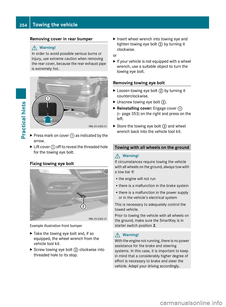
XPress mark on cover : as indicated by the
arrow.
XLift cover : off to reveal the threaded hole
for the towing eye bolt.
Fixing towing eye bolt
Example illustration front bumper
XTake the towing eye bolt and, if so
equipped, the wheel wrench from the
vehicle tool kit.
XScrew towing eye bolt ; clockwise into
threaded hole to its stop.
XInsert wheel wrench into towing eye and
tighten towing eye bolt ; by turning it
clockwise.
or
XIf your vehicle is not equipped with a wheel
wrench, use a suitable object to turn the
towing eye bolt.
Removing towing eye bolt
XLoosen towing eye bolt ; by turning it
counterclockwise.
XUnscrew towing eye bolt ;.XReinstalling cover: Engage cover :
(Y page 353) on the right and press on the
left.
XStore the towing eye bolt ; and wheel
wrench back into the vehicle tool kit.
Towing with all wheels on the ground
GWarning!
If circumstances require towing the vehicle
with all wheels on the ground, always tow with
a tow bar if:
Rthe engine will not run
Rthere is a malfunction in the brake system
Rthere is a malfunction in the power supply
or in the vehicle’s electrical system
This is necessary to adequately control the
towed vehicle.
Prior to towing the vehicle with all wheels on
the ground, make sure the SmartKey is in
starter switch position 2.
GWarning!
With the engine not running, there is no power
assistance for the brake and steering
systems. In this case, it is important to keep
in mind that a considerably higher degree of
effort is necessary to brake and steer the
vehicle. Adapt your driving accordingly.
354Towing the vehiclePractical hints
X164_AKB; 5; 31, en-USd2ureepe,Version: 2.11.8.12009-09-11T12:30:16+02:00 - Seite 354
Page 357 of 380
XMake sure the ignition is switched on.XWith the vehicle at a standstill, depress the
brake pedal and keep it pressed.XShift the automatic transmission into
neutral position N.XRelease the brake pedal.XIf engaged, release the parking brake.XSwitch on the hazard warning flasher
( Y page 101).
!
Keep in mind that it is important to have
the ignition switched on. Removing the
SmartKey from the starter switch or
opening a front door with the ignition
switched off will automatically shift the
automatic transmission into park position
P .
! The vehicle may be towed only for
distances up to 30 miles (50 km) and at a
speed not to exceed 30 mph (50 km/h).
i While being towed with the hazard
warning flasher in use, use the combination
switch in the usual manner to signal turns.
Only the selected turn signal will operate.
Upon canceling the turn signal, the hazard
warning flasher will operate again.
Stranded vehicle
Freeing a stranded vehicle, on which the
wheels are dug into sand or mud, should be
done with the greatest of care, especially if
the vehicle is heavily loaded.
Note the following when freeing a stranded
vehicle:
R Avoid pulling the vehicle abruptly or
diagonally, since it could result in damage
to the chassis alignment.
R Never try to free a vehicle that is still
coupled to a trailer.
R If possible, a vehicle equipped with a trailer
hitch receiver should be pulled backward in
its own previously made tracks.
Fuses
Introduction
The electrical fuses in your vehicle serve to
switch off malfunctioning power circuits.
If a fuse is blown, the components and
systems secured by that fuse will stop
operating.
GWarning!
Only use fuses approved by Mercedes-Benz
with the specified amperage for the system in
question and do not attempt to repair or
bridge a blown fuse. Using other than
approved fuses or using repaired or bridged
fuses may cause an overload leading to a fire,
and/or cause damage to electrical
components and/or systems. Have the cause
determined and remedied by an authorized
Mercedes-Benz Center.
A blown fuse must be replaced by an
appropriate spare fuse (recognizable by its
color or the fuse rating given on the fuse) of
the amperage recommended in the fuse
chart. Any Mercedes-Benz Center will be glad
to advise you on this subject.
i In case of a blown fuse contact Roadside
Assistance or an authorized Mercedes-
Benz Center.
If a newly inserted fuse blows again, have the
cause determined and rectified by an
authorized Mercedes-Benz Center.
The fuse chart is located in the cargo
compartment with the vehicle tool kit
( Y page 284). The fuse chart explains the fuse
allocation and fuse amperages.
Before replacing fuses
XEngage the parking brake.XMake sure the automatic transmission is in
park position P.
The transmission position indicator in the
multifunction display should be on P.XSwitch off all electrical consumers.Fuses355Practical hintsX164_AKB; 5; 31, en-USd2ureepe,Version: 2.11.8.12009-09-11T12:30:16+02:00 - Seite 355Z
Page 364 of 380
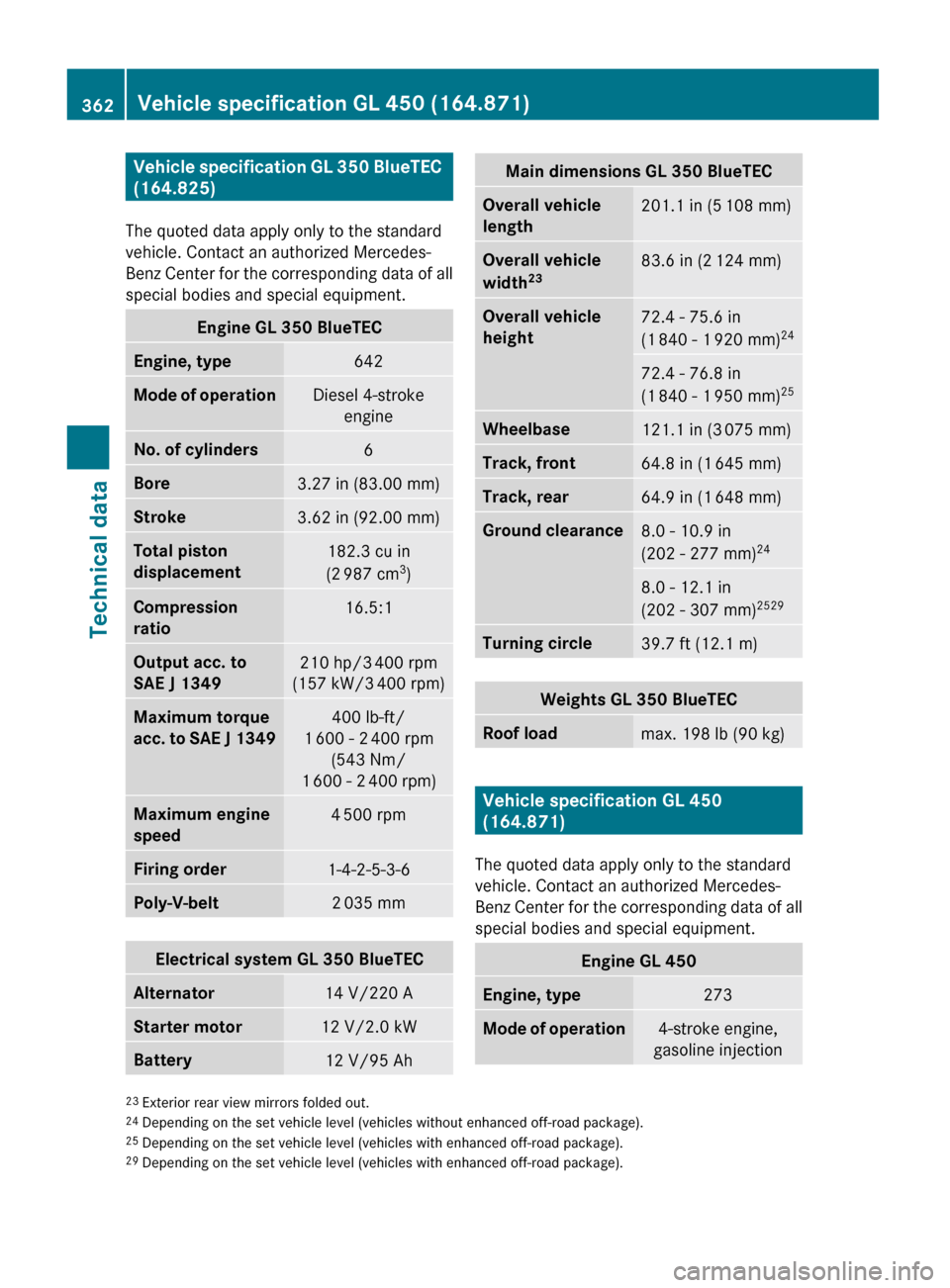
Vehicle specification GL 350 BlueTEC
(164.825)
The quoted data apply only to the standard
vehicle. Contact an authorized Mercedes-
Benz Center for the corresponding data of all
special bodies and special equipment.Engine GL 350 BlueTECEngine, type642Mode of operationDiesel 4-stroke engineNo. of cylinders6Bore3.27 in (83.00 mm)Stroke3.62 in (92.00 mm)Total piston
displacement182.3 cu in
(2 987 cm 3
)Compression
ratio16.5:1Output acc. to
SAE J 1349210 hp/3 400 rpm
(157 kW/3 400 rpm)Maximum torque
acc. to SAE J 1349400 lb-ft/
1 600 - 2 400 rpm
(543 Nm/
1 600 - 2 400 rpm)Maximum engine
speed4 500 rpmFiring order1-4-2-5-3-6Poly-V-belt2 035 mmElectrical system GL 350 BlueTECAlternator14 V/220 AStarter motor12 V/2.0 kWBattery12 V/95 AhMain dimensions GL 350 BlueTECOverall vehicle
length201.1 in (5 108 mm)Overall vehicle
width 2383.6 in (2
124 mm)Overall vehicle
height72.4 - 75.6 in
(1 840 - 1 920 mm) 2472.4 - 76.8 in
(1 840 - 1 950 mm) 25Wheelbase121.1 in (3
075 mm)Track, front64.8 in (1 645 mm)Track, rear64.9 in (1 648 mm)Ground clearance8.0 - 10.9 in
(202 - 277 mm) 248.0 - 12.1 in
(202 - 307 mm) 2529Turning circle39.7 ft (12.1 m)Weights GL 350 BlueTECRoof loadmax. 198 lb (90 kg)
Vehicle specification GL 450
(164.871)
The quoted data apply only to the standard
vehicle. Contact an authorized Mercedes-
Benz Center for the corresponding data of all
special bodies and special equipment.
Engine GL 450Engine, type273Mode of operation4-stroke engine,
gasoline injection23 Exterior rear view mirrors folded out.
24 Depending on the set vehicle level (vehicles without enhanced off-road package).
25 Depending on the set vehicle level (vehicles with enhanced off-road package).
29 Depending on the set vehicle level (vehicles with enhanced off-road package).362Vehicle specification GL 450 (164.871)Technical data
X164_AKB; 5; 31, en-USd2ureepe,Version: 2.11.8.12009-09-11T12:30:16+02:00 - Seite 362