2010 MERCEDES-BENZ GL550 lock
[x] Cancel search: lockPage 327 of 380

In case the central locking system does not
release the fuel filler flap, you can open it
manually.
The fuel filler flap release is located on the
passenger side in the cargo compartment
behind the cover.
XOpen the tailgate (Y page 75).XOpen the cover on the passenger-side trim
panel (Y page 332).
XPull red fuel filler flap release : in
direction of arrow.
The fuel filler flap is unlocked.
XOpen the fuel filler flap (Y page 226).XClose the cover.XClose the tailgate.
Resetting activated NECK-PRO active
front head restraints
If the NECK-PRO active front head restraints
have been triggered in a rear-end collision,
they must be reset.
You can tell that the NECK-PRO active front
head restraints have been triggered when
they have been moved forward and cannot be
adjusted.
GWarning!
For safety reasons, have the NECK-PRO active
front head restraints checked at an
authorized Mercedes-Benz Center after a
rear-end collision.
GWarning!
When pushing back the head restraint
cushion, make sure your fingers do not
become caught between the head restraint
cushion and the cover. Failing to do so may
lead to injury.
iPressing the head restraint cushion back
requires high force. If you encounter
difficulties when pushing the head restraint
back, please have the procedure
performed at an authorized Mercedes-Benz
Center.
Head restraints (standard)
XPull the top of the head restraint cushion in
direction of arrow : as far as it will go.
XAdjust the head restraint cushion
downward in direction of arrow ; as far as
it will go.
XFirmly press the top of the head restraint
cushion towards the head restraint cover in
direction of arrow = until it engages.
XRepeat this procedure on the NECK-PRO
active front head restraint for the second
front seat.
Resetting activated NECK-PRO active front head restraints325Practical hintsX164_AKB; 5; 31, en-USd2ureepe,Version: 2.11.8.12009-09-11T12:30:16+02:00 - Seite 325Z
Page 328 of 380
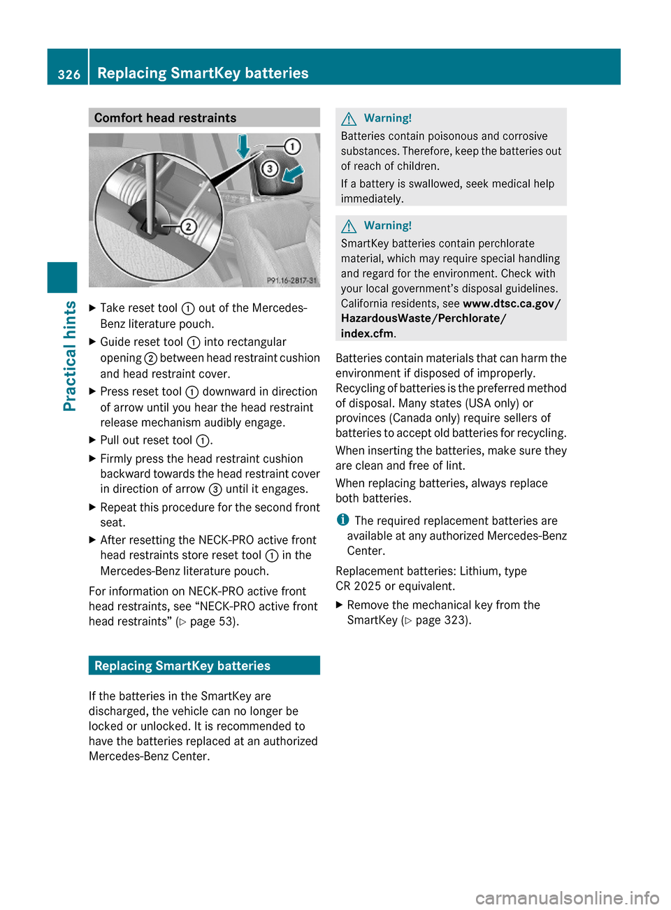
Comfort head restraintsXTake reset tool : out of the Mercedes-
Benz literature pouch.
XGuide reset tool : into rectangular
opening ; between head restraint cushion
and head restraint cover.
XPress reset tool : downward in direction
of arrow until you hear the head restraint
release mechanism audibly engage.
XPull out reset tool :.XFirmly press the head restraint cushion
backward towards the head restraint cover
in direction of arrow = until it engages.
XRepeat this procedure for the second front
seat.
XAfter resetting the NECK-PRO active front
head restraints store reset tool : in the
Mercedes-Benz literature pouch.
For information on NECK-PRO active front
head restraints, see “NECK-PRO active front
head restraints” (Y page 53).
Replacing SmartKey batteries
If the batteries in the SmartKey are
discharged, the vehicle can no longer be
locked or unlocked. It is recommended to
have the batteries replaced at an authorized
Mercedes-Benz Center.
GWarning!
Batteries contain poisonous and corrosive
substances. Therefore, keep the batteries out
of reach of children.
If a battery is swallowed, seek medical help
immediately.
GWarning!
SmartKey batteries contain perchlorate
material, which may require special handling
and regard for the environment. Check with
your local government’s disposal guidelines.
California residents, see www.dtsc.ca.gov/
HazardousWaste/Perchlorate/
index.cfm.
Batteries contain materials that can harm the
environment if disposed of improperly.
Recycling of batteries is the preferred method
of disposal. Many states (USA only) or
provinces (Canada only) require sellers of
batteries to accept old batteries for recycling.
When inserting the batteries, make sure they
are clean and free of lint.
When replacing batteries, always replace
both batteries.
iThe required replacement batteries are
available at any authorized Mercedes-Benz
Center.
Replacement batteries: Lithium, type
CR 2025 or equivalent.
XRemove the mechanical key from the
SmartKey (Y page 323).
326Replacing SmartKey batteriesPractical hints
X164_AKB; 5; 31, en-USd2ureepe,Version: 2.11.8.12009-09-11T12:30:16+02:00 - Seite 326
Page 329 of 380
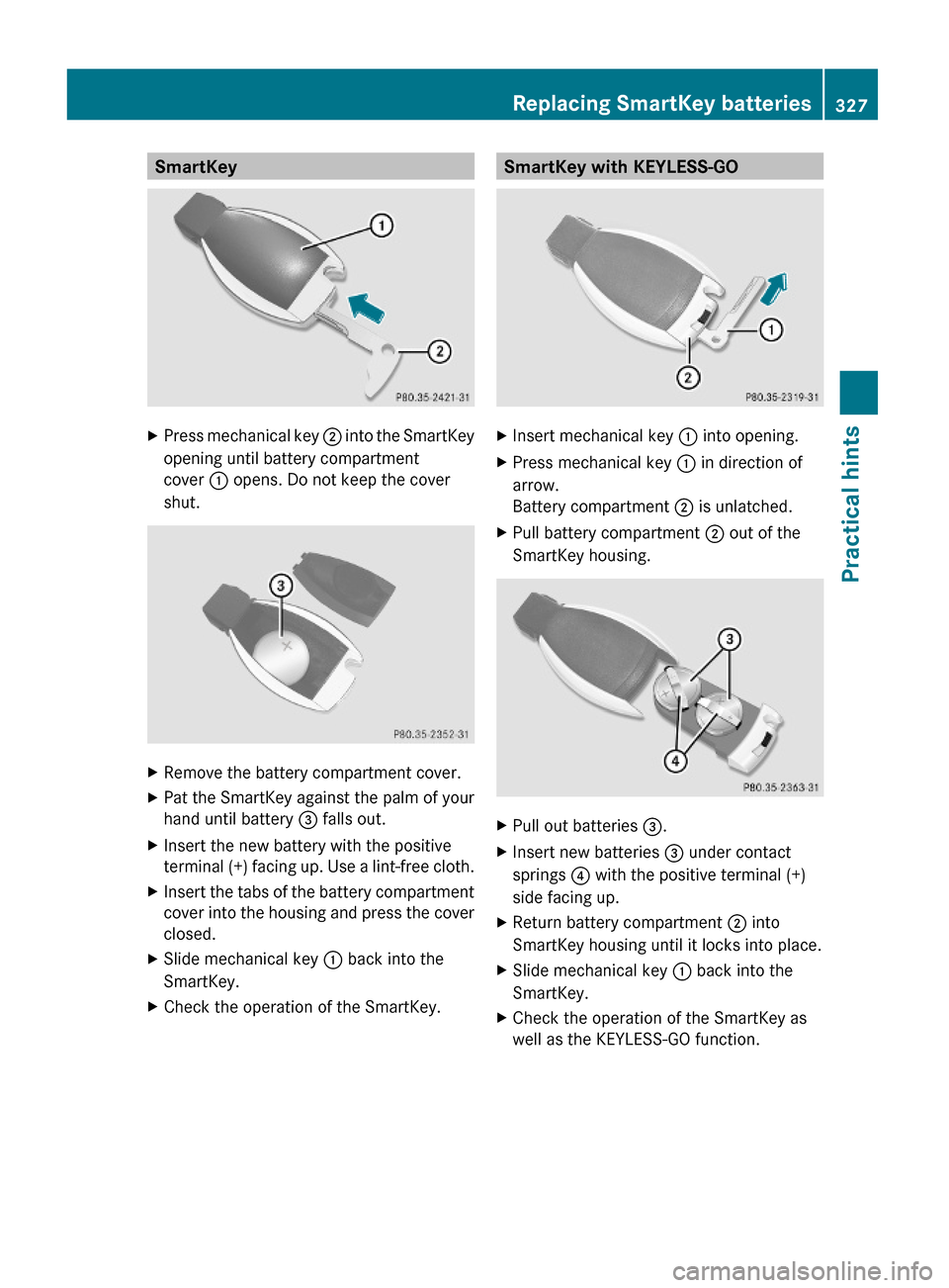
SmartKeyXPress mechanical key ; into the SmartKey
opening until battery compartment
cover : opens. Do not keep the cover
shut.
XRemove the battery compartment cover.XPat the SmartKey against the palm of your
hand until battery = falls out.
XInsert the new battery with the positive
terminal (+) facing up. Use a lint-free cloth.
XInsert the tabs of the battery compartment
cover into the housing and press the cover
closed.
XSlide mechanical key : back into the
SmartKey.
XCheck the operation of the SmartKey.SmartKey with KEYLESS-GOXInsert mechanical key : into opening.XPress mechanical key : in direction of
arrow.
Battery compartment ; is unlatched.
XPull battery compartment ; out of the
SmartKey housing.
XPull out batteries =.XInsert new batteries = under contact
springs ? with the positive terminal (+)
side facing up.
XReturn battery compartment ; into
SmartKey housing until it locks into place.
XSlide mechanical key : back into the
SmartKey.
XCheck the operation of the SmartKey as
well as the KEYLESS-GO function.
Replacing SmartKey batteries327Practical hintsX164_AKB; 5; 31, en-USd2ureepe,Version: 2.11.8.12009-09-11T12:30:16+02:00 - Seite 327Z
Page 333 of 380
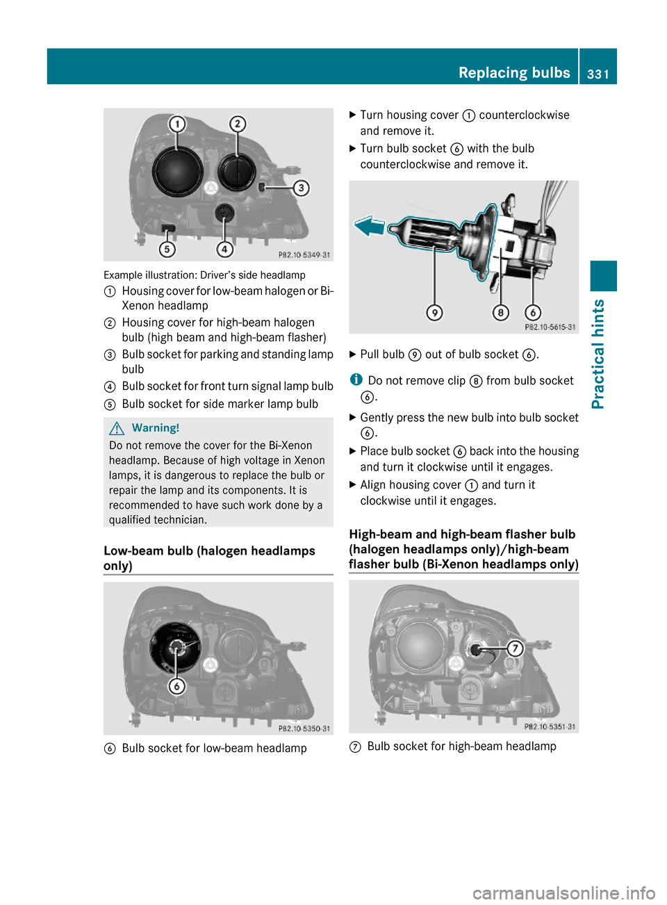
Example illustration: Driver’s side headlamp
:Housing cover for low-beam halogen or Bi-
Xenon headlamp
;Housing cover for high-beam halogen
bulb (high beam and high-beam flasher)
=Bulb socket for parking and standing lamp
bulb
?Bulb socket for front turn signal lamp bulbABulb socket for side marker lamp bulbGWarning!
Do not remove the cover for the Bi-Xenon
headlamp. Because of high voltage in Xenon
lamps, it is dangerous to replace the bulb or
repair the lamp and its components. It is
recommended to have such work done by a
qualified technician.
Low-beam bulb (halogen headlamps
only)
BBulb socket for low-beam headlampXTurn housing cover : counterclockwise
and remove it.
XTurn bulb socket B with the bulb
counterclockwise and remove it.
XPull bulb E out of bulb socket B.
iDo not remove clip D from bulb socket
B.
XGently press the new bulb into bulb socket
B.
XPlace bulb socket B back into the housing
and turn it clockwise until it engages.
XAlign housing cover : and turn it
clockwise until it engages.
High-beam and high-beam flasher bulb
(halogen headlamps only)/high-beam
flasher bulb (Bi-Xenon headlamps only)
CBulb socket for high-beam headlampReplacing bulbs331Practical hintsX164_AKB; 5; 31, en-USd2ureepe,Version: 2.11.8.12009-09-11T12:30:16+02:00 - Seite 331Z
Page 334 of 380
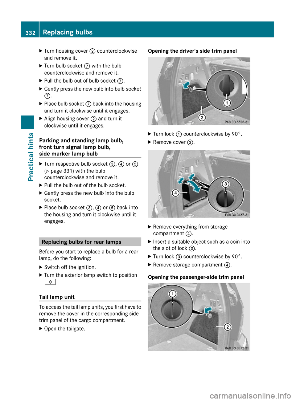
XTurn housing cover ; counterclockwise
and remove it.
XTurn bulb socket C with the bulb
counterclockwise and remove it.
XPull the bulb out of bulb socket C.XGently press the new bulb into bulb socket
C.
XPlace bulb socket C back into the housing
and turn it clockwise until it engages.
XAlign housing cover ; and turn it
clockwise until it engages.
Parking and standing lamp bulb,
front turn signal lamp bulb,
side marker lamp bulb
XTurn respective bulb socket =, ? or A
(Y page 331) with the bulb
counterclockwise and remove it.
XPull the bulb out of the bulb socket.XGently press the new bulb into the bulb
socket.
XPlace bulb socket =, ? or A back into
the housing and turn it clockwise until it
engages.
Replacing bulbs for rear lamps
Before you start to replace a bulb for a rear
lamp, do the following:
XSwitch off the ignition.XTurn the exterior lamp switch to position
$.
Tail lamp unit
To access the tail lamp units, you first have to
remove the cover in the corresponding side
trim panel of the cargo compartment.
XOpen the tailgate.Opening the driver’s side trim panelXTurn lock : counterclockwise by 90°.XRemove cover ;.XRemove everything from storage
compartment ?.
XInsert a suitable object such as a coin into
the slot of lock =.
XTurn lock = counterclockwise by 90°.XRemove storage compartment ?.
Opening the passenger-side trim panel
332Replacing bulbsPractical hints
X164_AKB; 5; 31, en-USd2ureepe,Version: 2.11.8.12009-09-11T12:30:16+02:00 - Seite 332
Page 335 of 380

XInsert a suitable object such as a coin into
the slot of lock :.
XTurn lock : by 90° in direction of the
arrow.
XRemove cover ;.
Replacing bulbs
Example illustration: LED rear lamp driver’s side
:Backup lamp bulb socket;Rear fog lamp bulb socket (driver’s side
only)
XDepending on which bulb needs to be
replaced, turn the respective bulb socket
counterclockwise.
XPull the bulb socket out of the housing.XBackup lamp bulb :: Gently press onto
the bulb and turn it counterclockwise out
of its bulb socket.
XGently press the new bulb into its bulb
socket and turn it clockwise until it
engages.
XRear fog lamp bulb ;: Pull the bulb out
of its bulb socket.
XGently press the new bulb into its bulb
socket.
XAlign the bulb socket and turn it clockwise.XMake sure the bulb socket is attached
properly.
XClose the respective cover in the cargo
compartment.
XClose the tailgate.License plate lampsXLoosen screws : of lamp cover to be
removed.
XRemove lamp cover ;.XReplace the bulb.XReinstall lamp cover ;.XRetighten screws :.
Adjusting headlamp aim
:V Vertical centerline;H Horizontal mounting height, measured
from the center
Replacing bulbs333Practical hintsX164_AKB; 5; 31, en-USd2ureepe,Version: 2.11.8.12009-09-11T12:30:16+02:00 - Seite 333Z
Page 336 of 380
Correct headlamp adjustment is extremely
important. High beam adjustments
simultaneously aim the low beam. To check
and readjust a headlamp, follow the steps
described:
XPark the vehicle on a level surface 25 feet
(7.6 m) from a vertical test screen or wall.
XMake sure the vehicle has a normal tailgate
load.
XSwitch on the low beam headlamps L.
If the beam does not show a beam pattern as
indicated in the figure left, then follow the
steps below:
XOpen the hood (Y page 228).
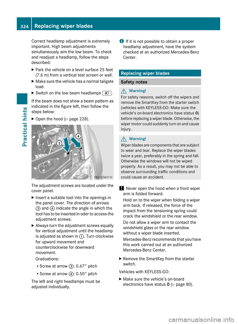
The adjustment screws are located under the
cover panel.
XInsert a suitable tool into the openings in
the panel cover. The direction of arrows
= and ? indicate the angle in which the
tool has to be inserted in oder to access the
adjustment screws.
XAlways turn the adjustment screws equally
for vertical adjustment until the headlamp
is adjusted as shown in :. Turn clockwise
for upward movement and
counterclockwise for downward
movement.
Graduations:
RScrew at arrow =: 0.67° pitch
RScrew at arrow ?: 0.50° pitch
The left and right headlamps must be
adjusted individually.
iIf it is not possible to obtain a proper
headlamp adjustment, have the system
checked at an authorized Mercedes-Benz
Center.
Replacing wiper blades
Safety notes
GWarning!
For safety reasons, switch off the wipers and
remove the SmartKey from the starter switch
(vehicles with KEYLESS-GO: Make sure the
vehicle’s on-board electronics have status 0)
before replacing a wiper blade. Otherwise, the
wiper motor could suddenly turn on and cause
injury.
GWarning!
Wiper blades are components that are subject
to wear and tear. Replace the wiper blades
twice a year, preferably in the spring and fall.
Otherwise the windows will not be wiped
properly. As a result, you may not be able to
observe surrounding traffic conditions and
could cause an accident.
! Never open the hood when a front wiper
arm is folded forward.
Hold on to the wiper when folding a wiper
arm back. If released, the force of the
impact from the tensioning spring could
crack the windshield or the rear window.
Do not allow a wiper arm to contact the
windshield glass or the rear window
without a wiper blade inserted.
Mercedes-Benz recommends that you have
this work carried out at an authorized
Mercedes-Benz Center.
XRemove the SmartKey from the starter
switch.
Vehicles with KEYLESS-GO:
XMake sure the vehicle’s on-board
electronics have status 0 (Y page 80).
334Replacing wiper bladesPractical hints
X164_AKB; 5; 31, en-USd2ureepe,Version: 2.11.8.12009-09-11T12:30:16+02:00 - Seite 334
Page 338 of 380
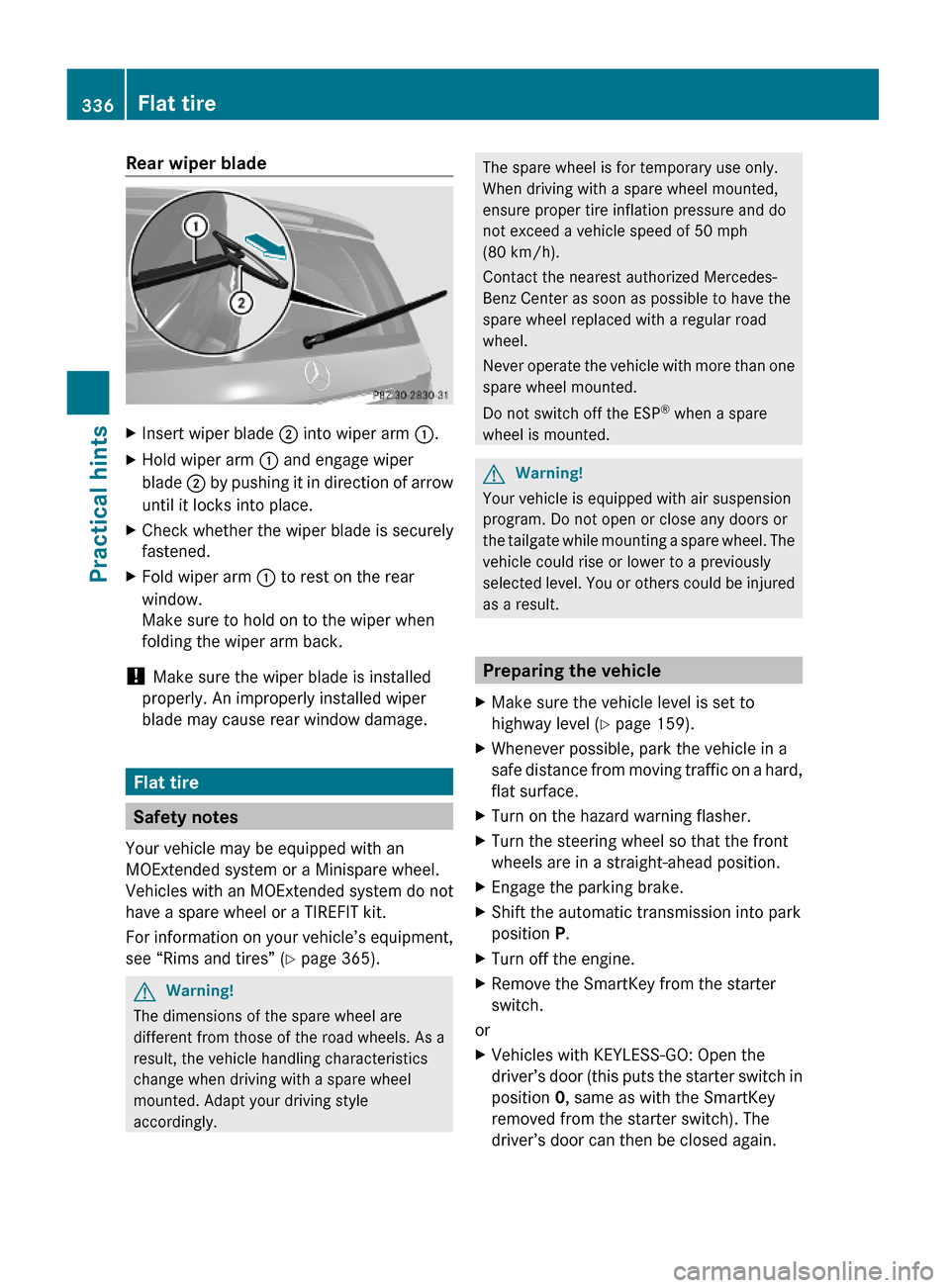
Rear wiper bladeXInsert wiper blade ; into wiper arm :.XHold wiper arm : and engage wiper
blade ; by pushing it in direction of arrow
until it locks into place.
XCheck whether the wiper blade is securely
fastened.
XFold wiper arm : to rest on the rear
window.
Make sure to hold on to the wiper when
folding the wiper arm back.
! Make sure the wiper blade is installed
properly. An improperly installed wiper
blade may cause rear window damage.
Flat tire
Safety notes
Your vehicle may be equipped with an
MOExtended system or a Minispare wheel.
Vehicles with an MOExtended system do not
have a spare wheel or a TIREFIT kit.
For information on your vehicle’s equipment,
see “Rims and tires” (Y page 365).
GWarning!
The dimensions of the spare wheel are
different from those of the road wheels. As a
result, the vehicle handling characteristics
change when driving with a spare wheel
mounted. Adapt your driving style
accordingly.
The spare wheel is for temporary use only.
When driving with a spare wheel mounted,
ensure proper tire inflation pressure and do
not exceed a vehicle speed of 50 mph
(80 km/h).
Contact the nearest authorized Mercedes-
Benz Center as soon as possible to have the
spare wheel replaced with a regular road
wheel.
Never operate the vehicle with more than one
spare wheel mounted.
Do not switch off the ESP® when a spare
wheel is mounted.
GWarning!
Your vehicle is equipped with air suspension
program. Do not open or close any doors or
the tailgate while mounting a spare wheel. The
vehicle could rise or lower to a previously
selected level. You or others could be injured
as a result.
Preparing the vehicle
XMake sure the vehicle level is set to
highway level (Y page 159).
XWhenever possible, park the vehicle in a
safe distance from moving traffic on a hard,
flat surface.
XTurn on the hazard warning flasher.XTurn the steering wheel so that the front
wheels are in a straight-ahead position.
XEngage the parking brake.XShift the automatic transmission into park
position P.
XTurn off the engine.XRemove the SmartKey from the starter
switch.
or
XVehicles with KEYLESS-GO: Open the
driver’s door (this puts the starter switch in
position 0, same as with the SmartKey
removed from the starter switch). The
driver’s door can then be closed again.
336Flat tirePractical hints
X164_AKB; 5; 31, en-USd2ureepe,Version: 2.11.8.12009-09-11T12:30:16+02:00 - Seite 336