2010 MERCEDES-BENZ GL450 weight
[x] Cancel search: weightPage 198 of 380
Carriers
For information about further carriers,
contact an authorized Mercedes-Benz
Center.
GWarning!
Only use carriers when the crossbars have
been completely mounted. The left and right
roof rails are only stabilized by means of the
crossbars mounted.
Follow the manufacturer’s installation
instructions. Otherwise, an improperly
attached carrier or its load could become
detached from the vehicle.
Do not exceed the maximum roof load of
198 lb (90 kg).
Take into consideration that when the roof is
loaded, the handling characteristics are
different from those when operating the
vehicle without the roof loaded.
Make sure
Ryou can raise the tilt/sliding sunroof at the
rear completely
Ryou can open the tailgate completely
iThe following accessories are available
for your Mercedes-Benz:
RRoof Cargo Container – Small, Medium,
or Large
RSki and Snowboard Carrier – Standard
RSki and Snowboard Carrier – Deluxe
(Only in connection with corresponding
adapter.)
For more information on Mercedes-Benz
accessories, contact your authorized
Mercedes-Benz Center.
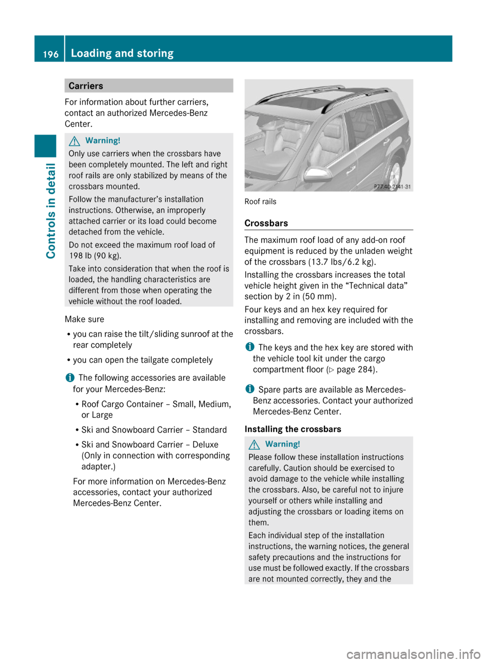
Roof rails
Crossbars
The maximum roof load of any add-on roof
equipment is reduced by the unladen weight
of the crossbars (13.7 Ibs/6.2 kg).
Installing the crossbars increases the total
vehicle height given in the “Technical data”
section by 2 in (50 mm).
Four keys and an hex key required for
installing and removing are included with the
crossbars.
iThe keys and the hex key are stored with
the vehicle tool kit under the cargo
compartment floor (Y page 284).
iSpare parts are available as Mercedes-
Benz accessories. Contact your authorized
Mercedes-Benz Center.
Installing the crossbars
GWarning!
Please follow these installation instructions
carefully. Caution should be exercised to
avoid damage to the vehicle while installing
the crossbars. Also, be careful not to injure
yourself or others while installing and
adjusting the crossbars or loading items on
them.
Each individual step of the installation
instructions, the warning notices, the general
safety precautions and the instructions for
use must be followed exactly. If the crossbars
are not mounted correctly, they and the
196Loading and storingControls in detail
X164_AKB; 5; 31, en-USd2ureepe,Version: 2.11.8.12009-09-11T12:30:16+02:00 - Seite 196
Page 199 of 380

objects attached to them could come loose
from your vehicle and cause an accident,
thereby injuring you and other persons and/
or causing damage to property, including
damage to your vehicle.GWarning!
Every time the crossbars are mounted, before
you set off on a journey and periodically
during longer journeys, check all the screws
on the crossbars to make sure that they are
secure, and tighten them if necessary. Repeat
these checks at regular intervals as road-
surface conditions dictate, and at least after
every 1500 miles (2500 km) of continuous
use.
Otherwise, the crossbars, mounted
accessories and the objects attached to them
could come loose from the vehicle causing an
accident, thereby injuring you and other
persons and/or causing damage to property,
including damage to your vehicle.
Do not use lubricant on the screws of the
crossbars. The screws could work loose and
the crossbars could become detached from
your vehicle, together with the objects
attached to them causing an accident,
thereby injuring you and other persons and/
or causing damage to property, including
damage to your vehicle.
GWarning!
Only install the crossbars at the exact
locations designated on the roof rails. The
designated locations for the front crossbars
are between the markings engraved on the
inside of the roof rails. The designated
locations for the rear crossbars are between
the gaps on the roof rails.
Otherwise, the crossbars, mounted
accessories and the objects attached to them
could come loose from the vehicle causing an
accident, thereby injuring you and other
persons and/or causing damage to property,
including damage to your vehicle.
GWarning!
A roof load creates a greater surface area
exposed to the wind and causes the vehicle
to have a higher center of gravity, thereby
changing the vehicle’s driving characteristics.
Accordingly, the additional weight on the roof
of the vehicle can have a detrimental effect
on braking, cornering and acceleration.
Never exceed the maximum permissible roof
load or the maximum permissible vehicle
weight, even when accessories for the
crossbars (e.g. ski racks, bicycle racks, etc.)
are being used. Overloading the vehicle could
result in an accident. When calculating the
weight placed on the roof please make sure
to add the weight of the crossbars, accessory
racks and the load carried together.
Always adapt your driving style to the road,
traffic and weather conditions, and drive with
added caution when the roof is loaded.
Always drive with extreme care when the
carrier is loaded. Take into consideration that
when the carrier is loaded, the handling
characteristics are different from those when
operating the vehicle without a carrier loaded.
GWarning!
Do not use accessories which have not been
approved by Mercedes-Benz for use in
conjunction with these crossbars. If non-
approved accessories are used, these
accessories and/or the objects attached to
them could come loose from the vehicle,
thereby injuring you and other persons and/
or causing damage to property, including
damage to your vehicle.
! Have a second person assist you when
installing the crossbars. The vehicle could
otherwise be damaged.
! Objects attached to the crossbar
system’s accessories must not be allowed
to restrict the movement of the tilt/sliding
sunroof. The tilt/sliding sunroof could
otherwise be damaged when it is raised.
Loading and storing197Controls in detailX164_AKB; 5; 31, en-USd2ureepe,Version: 2.11.8.12009-09-11T12:30:16+02:00 - Seite 197Z
Page 202 of 380
XUnlock cover cap ; with key :.XRemove cover cap ;.XTurn screws for clamping claws A
counterclockwise until the crossbars can
be lifted from the roof rails.
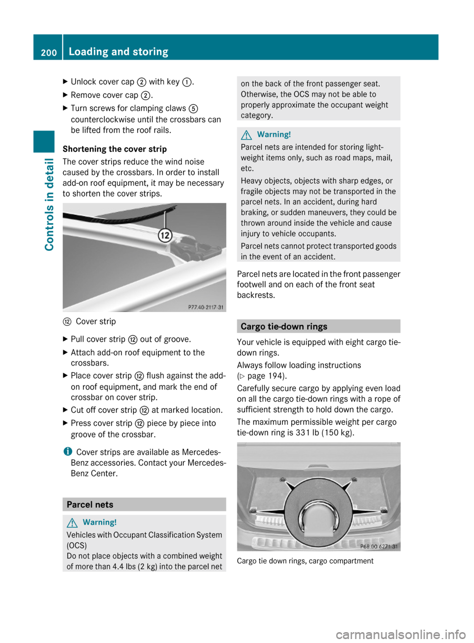
Shortening the cover strip
The cover strips reduce the wind noise
caused by the crossbars. In order to install
add-on roof equipment, it may be necessary
to shorten the cover strips.
HCover stripXPull cover strip H out of groove.XAttach add-on roof equipment to the
crossbars.
XPlace cover strip H flush against the add-
on roof equipment, and mark the end of
crossbar on cover strip.
XCut off cover strip H at marked location.XPress cover strip H piece by piece into
groove of the crossbar.
iCover strips are available as Mercedes-
Benz accessories. Contact your Mercedes-
Benz Center.
Parcel nets
GWarning!
Vehicles with Occupant Classification System
(OCS)
Do not place objects with a combined weight
of more than 4.4 lbs (2 kg) into the parcel net
on the back of the front passenger seat.
Otherwise, the OCS may not be able to
properly approximate the occupant weight
category.
GWarning!
Parcel nets are intended for storing light-
weight items only, such as road maps, mail,
etc.
Heavy objects, objects with sharp edges, or
fragile objects may not be transported in the
parcel nets. In an accident, during hard
braking, or sudden maneuvers, they could be
thrown around inside the vehicle and cause
injury to vehicle occupants.
Parcel nets cannot protect transported goods
in the event of an accident.
Parcel nets are located in the front passenger
footwell and on each of the front seat
backrests.
Cargo tie-down rings
Your vehicle is equipped with eight cargo tie-
down rings.
Always follow loading instructions
(Y page 194).
Carefully secure cargo by applying even load
on all the cargo tie-down rings with a rope of
sufficient strength to hold down the cargo.
The maximum permissible weight per cargo
tie-down ring is 331 lb (150 kg).
Cargo tie down rings, cargo compartment
200Loading and storingControls in detail
X164_AKB; 5; 31, en-USd2ureepe,Version: 2.11.8.12009-09-11T12:30:16+02:00 - Seite 200
Page 203 of 380
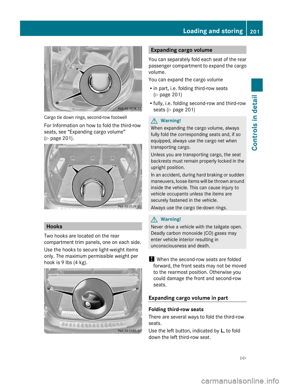
Cargo tie down rings, second-row footwell
For Information on how to fold the third-row
seats, see “Expanding cargo volume”
(Y page 201).
Hooks
Two hooks are located on the rear
compartment trim panels, one on each side.
Use the hooks to secure light-weight items
only. The maximum permissible weight per
hook is 9 lbs (4 kg).
Expanding cargo volume
You can separately fold each seat of the rear
passenger compartment to expand the cargo
volume.
You can expand the cargo volume
Rin part, i.e. folding third-row seats
(Y page 201)
Rfully, i.e. folding second-row and third-row
seats (Y page 201)
GWarning!
When expanding the cargo volume, always
fully fold the corresponding seats and, if so
equipped, always use the cargo net when
transporting cargo.
Unless you are transporting cargo, the seat
backrests must remain properly locked in the
upright position.
In an accident, during hard braking or sudden
maneuvers, loose items will be thrown around
inside the vehicle. This can cause injury to
vehicle occupants unless the items are
securely fastened in the vehicle.
Always use the cargo tie-down rings.
GWarning!
Never drive a vehicle with the tailgate open.
Deadly carbon monoxide (CO) gases may
enter vehicle interior resulting in
unconsciousness and death.
! When the second-row seats are folded
forward, the front seats may not be moved
to the rearmost position. Otherwise you
could damage the front and second-row
seats.
Expanding cargo volume in part
Folding third-row seats
There are several ways to fold the third-row
seats.
Use the left button, indicated by L, to fold
down the left third-row seat.
Loading and storing201Controls in detailX164_AKB; 5; 31, en-USd2ureepe,Version: 2.11.8.12009-09-11T12:30:16+02:00 - Seite 201Z
Page 212 of 380
! Do not sit on or lean your body weight
against the armrest when it is folded down,
as you could otherwise damage it.
Cup holders in third-row side trims
Cup holders are located in the side trims of
the third-row seats.
Sun visors
GWarning!
Do not use the vanity mirror while driving.
Keep the vanity mirrors in the sun visors
closed while vehicle is in motion. Reflected
glare can endanger you and others.
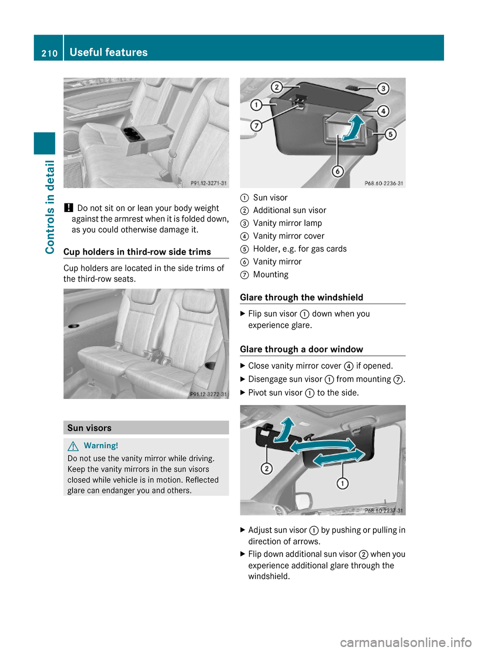
:Sun visor;Additional sun visor=Vanity mirror lamp?Vanity mirror coverAHolder, e.g. for gas cardsBVanity mirrorCMounting
Glare through the windshield
XFlip sun visor : down when you
experience glare.
Glare through a door window
XClose vanity mirror cover ? if opened.XDisengage sun visor : from mounting C.XPivot sun visor : to the side.XAdjust sun visor : by pushing or pulling in
direction of arrows.
XFlip down additional sun visor ; when you
experience additional glare through the
windshield.
210Useful featuresControls in detail
X164_AKB; 5; 31, en-USd2ureepe,Version: 2.11.8.12009-09-11T12:30:16+02:00 - Seite 210
Page 237 of 380
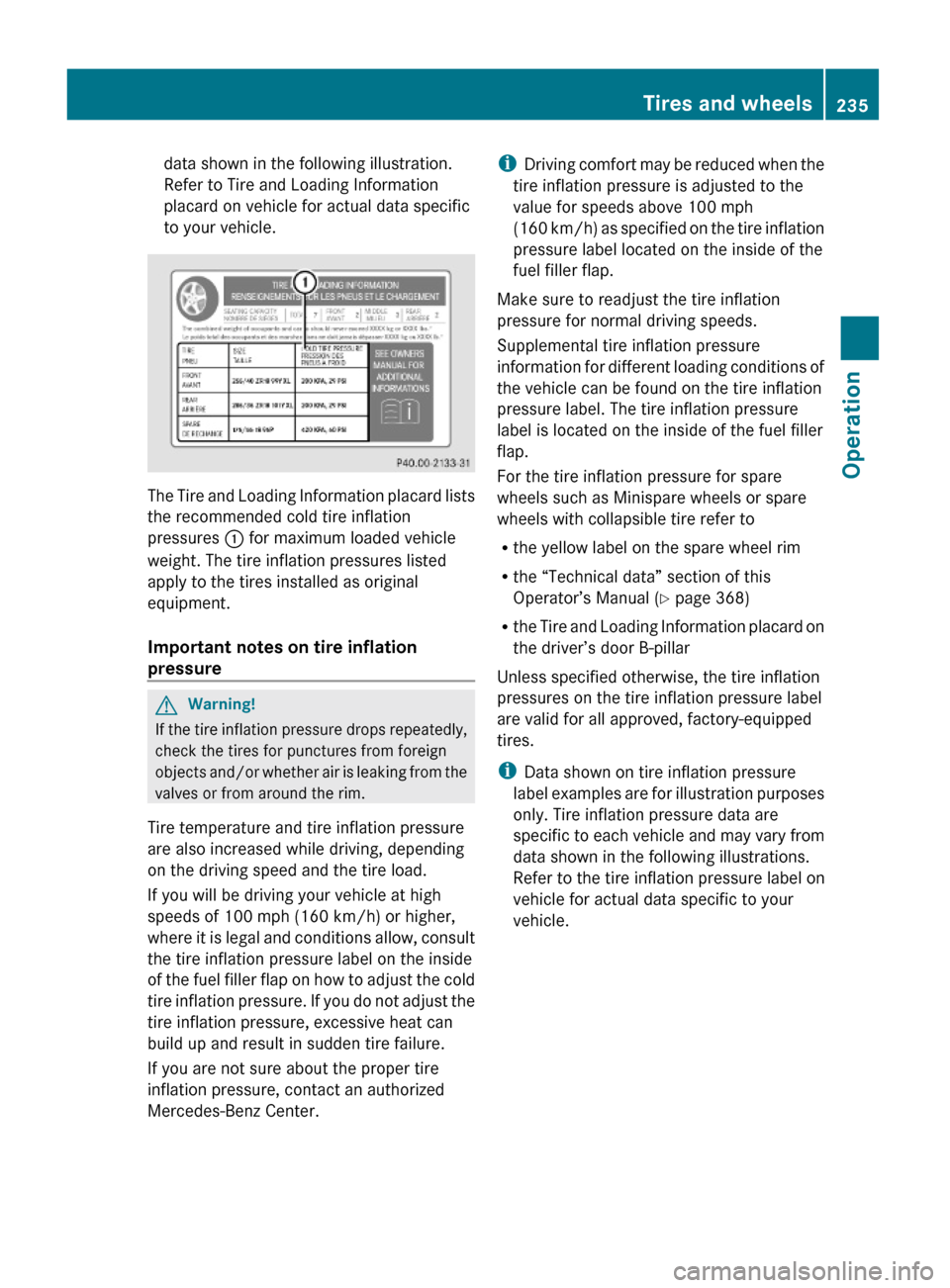
data shown in the following illustration.
Refer to Tire and Loading Information
placard on vehicle for actual data specific
to your vehicle.
The Tire and Loading Information placard lists
the recommended cold tire inflation
pressures : for maximum loaded vehicle
weight. The tire inflation pressures listed
apply to the tires installed as original
equipment.
Important notes on tire inflation
pressure
GWarning!
If the tire inflation pressure drops repeatedly,
check the tires for punctures from foreign
objects and/or whether air is leaking from the
valves or from around the rim.
Tire temperature and tire inflation pressure
are also increased while driving, depending
on the driving speed and the tire load.
If you will be driving your vehicle at high
speeds of 100 mph (160 km/h) or higher,
where it is legal and conditions allow, consult
the tire inflation pressure label on the inside
of the fuel filler flap on how to adjust the cold
tire inflation pressure. If you do not adjust the
tire inflation pressure, excessive heat can
build up and result in sudden tire failure.
If you are not sure about the proper tire
inflation pressure, contact an authorized
Mercedes-Benz Center.
iDriving comfort may be reduced when the
tire inflation pressure is adjusted to the
value for speeds above 100 mph
(160 km/h) as specified on the tire inflation
pressure label located on the inside of the
fuel filler flap.
Make sure to readjust the tire inflation
pressure for normal driving speeds.
Supplemental tire inflation pressure
information for different loading conditions of
the vehicle can be found on the tire inflation
pressure label. The tire inflation pressure
label is located on the inside of the fuel filler
flap.
For the tire inflation pressure for spare
wheels such as Minispare wheels or spare
wheels with collapsible tire refer to
Rthe yellow label on the spare wheel rim
Rthe “Technical data” section of this
Operator’s Manual (Y page 368)
Rthe Tire and Loading Information placard on
the driver’s door B-pillar
Unless specified otherwise, the tire inflation
pressures on the tire inflation pressure label
are valid for all approved, factory-equipped
tires.
iData shown on tire inflation pressure
label examples are for illustration purposes
only. Tire inflation pressure data are
specific to each vehicle and may vary from
data shown in the following illustrations.
Refer to the tire inflation pressure label on
vehicle for actual data specific to your
vehicle.
Tires and wheels235OperationX164_AKB; 5; 31, en-USd2ureepe,Version: 2.11.8.12009-09-11T12:30:16+02:00 - Seite 235Z
Page 244 of 380
Maximum tire inflation pressureGWarning!
Never exceed the maximum tire inflation
pressure. Follow recommended tire inflation
pressures.
Do not underinflate tires. Underinflated tires
wear excessively and/or unevenly, adversely
affect handling and fuel economy, and are
more likely to fail from being overheated.
Do not overinflate tires. Overinflated tires can
adversely affect handling and ride comfort,
wear unevenly, increase stopping distance,
and result in sudden deflation (blowout)
because they are more likely to become
punctured or damaged by road debris,
potholes etc.
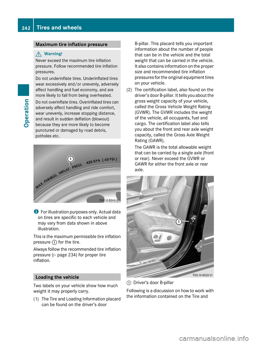
iFor illustration purposes only. Actual data
on tires are specific to each vehicle and
may vary from data shown in above
illustration.
This is the maximum permissible tire inflation
pressure : for the tire.
Always follow the recommended tire inflation
pressure (Y page 234) for proper tire
inflation.
Loading the vehicle
Two labels on your vehicle show how much
weight it may properly carry.
(1)The Tire and Loading Information placard
can be found on the driver’s door
B-pillar. This placard tells you important
information about the number of people
that can be in the vehicle and the total
weight that can be carried in the vehicle.
It also contains information on the proper
size and recommended tire inflation
pressures for the original equipment tires
on your vehicle.
(2)The certification label, also found on the
driver’s door B-pillar. It tells you about the
gross weight capacity of your vehicle,
called the Gross Vehicle Weight Rating
(GVWR). The GVWR includes the weight
of the vehicle, all occupants, fuel and
cargo. The certification label also tells
you about the front and rear axle weight
capacity, called the Gross Axle Weight
Rating (GAWR).
The GAWR is the total allowable weight
that can be carried by a single axle (front
or rear). Never exceed the GVWR or
GAWR for either the front axle or rear
axle.
:Driver’s door B-pillar
Following is a discussion on how to work with
the information contained on the Tire and
242Tires and wheelsOperation
X164_AKB; 5; 31, en-USd2ureepe,Version: 2.11.8.12009-09-11T12:30:16+02:00 - Seite 242
Page 245 of 380
Loading Information placard with regards to
loading your vehicle.
Tire and Loading Information
GWarning!
Do not overload the tires by exceeding the
specified load limit as indicated on the Tire
and Loading Information placard on the
driver’s door B-pillar. Overloading the tires
can overheat them, possibly causing a
blowout. Overloading the tires can also result
in handling or steering problems, or brake
failure.
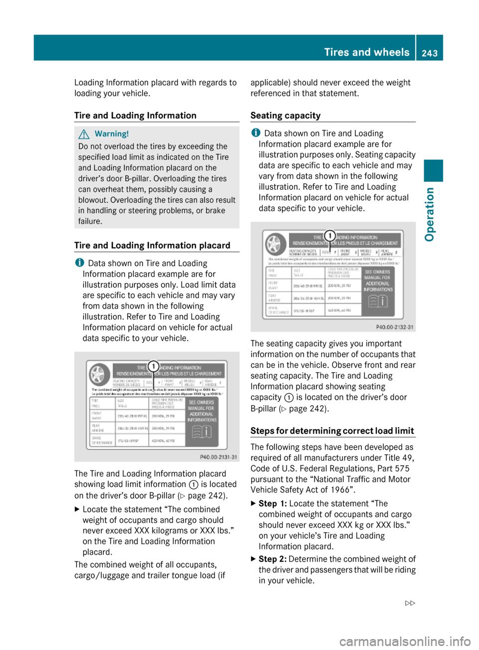
Tire and Loading Information placard
iData shown on Tire and Loading
Information placard example are for
illustration purposes only. Load limit data
are specific to each vehicle and may vary
from data shown in the following
illustration. Refer to Tire and Loading
Information placard on vehicle for actual
data specific to your vehicle.
The Tire and Loading Information placard
showing load limit information : is located
on the driver’s door B-pillar (Y page 242).
XLocate the statement “The combined
weight of occupants and cargo should
never exceed XXX kilograms or XXX lbs.”
on the Tire and Loading Information
placard.
The combined weight of all occupants,
cargo/luggage and trailer tongue load (if
applicable) should never exceed the weight
referenced in that statement.
Seating capacity
iData shown on Tire and Loading
Information placard example are for
illustration purposes only. Seating capacity
data are specific to each vehicle and may
vary from data shown in the following
illustration. Refer to Tire and Loading
Information placard on vehicle for actual
data specific to your vehicle.
The seating capacity gives you important
information on the number of occupants that
can be in the vehicle. Observe front and rear
seating capacity. The Tire and Loading
Information placard showing seating
capacity : is located on the driver’s door
B-pillar (Y page 242).
Steps for determining correct load limit
The following steps have been developed as
required of all manufacturers under Title 49,
Code of U.S. Federal Regulations, Part 575
pursuant to the “National Traffic and Motor
Vehicle Safety Act of 1966”.
XStep 1: Locate the statement “The
combined weight of occupants and cargo
should never exceed XXX kg or XXX lbs.”
on your vehicle’s Tire and Loading
Information placard.
XStep 2: Determine the combined weight of
the driver and passengers that will be riding
in your vehicle.
Tires and wheels243OperationX164_AKB; 5; 31, en-USd2ureepe,Version: 2.11.8.12009-09-11T12:30:16+02:00 - Seite 243Z