2010 MERCEDES-BENZ GL450 air condition
[x] Cancel search: air conditionPage 193 of 380
iThe manually selected air recirculation
mode is deactivated automatically:
R after 5 minutes if the outside
temperature is below approximately
41‡ (5†)
R after 5 minutes if the air conditioning and
air-drying are turned off
R after 30 minutes if the outside
temperature is above approximately
41‡ (5†)
At outside temperatures above 79‡ (26†)
the system will not automatically switch back
to outside air. A quantity of outside air is
added after approximately 30 minutes.
Residual heat and ventilation
With the engine switched off, it is possible to
continue to heat or ventilate the interior for
up to 30 minutes. This feature makes use of
the residual heat produced by the engine.
i How long the system will provide heating
depends on the coolant temperature and
the battery voltage.
Regardless of the temperature and air
volume set on the climate control panel, an
interior temperature is aimed at by 72‡
(22† ) and the blower runs on low speed to
protect the vehicle battery.
XActivating: Switch off the ignition.XPress button Á.
The indicator lamp in the button comes on.XDeactivating: Press button Á again.
The indicator lamp in the button goes out.
The residual heat is deactivated
automatically:
R when the ignition is switched on
R after approximately 30 minutes
R if the battery voltage drops
R if the coolant temperature is too low
Using driver-side settings for all
temperature zones
This feature is only available in Canada
vehicles.
You can use the settings of the driver’s side,
such as temperature, air volume and air
distribution, for all temperature zones. These
settings only need to be made once and the
climate control system will automatically
regulate the settings for all temperature
zones quickly and comfortably.XActivating: Adjust the air temperature, air
volume and air distribution.XPress button ¸.
The indicator lamp in the button comes on.
The driver-side settings are used for all
temperature zones.XDeactivating: Press button ¸ again.
The indicator lamp in the button goes out.
i If you manually set the temperature, air
volume or air distribution for the passenger
side or the rear passenger compartment
when the MONO setting is active, the
MONO setting will be switched off.
Rear window defroster
GWarning!
Any accumulation of snow and ice should be
removed from the rear window before driving.
Visibility could otherwise be impaired,
endangering you and others.
The rear window defroster uses a large
amount of power. To keep the battery drain
to a minimum, switch off the defroster as
soon as the rear window is clear. The
defroster is switched off automatically after
some time of operation depending on the
outside temperature.
Rear window defroster191Controls in detailX164_AKB; 5; 31, en-USd2ureepe,Version: 2.11.8.12009-09-11T12:30:16+02:00 - Seite 191Z
Page 217 of 380
The Tele Aid system consists of three types
of response:
R Automatic and manual emergency
R Roadside Assistance
R Information
To adjust the speaker volume during a Tele
Aid call do the following:XPress button W or X on the
multifunction steering wheel.
or
XUse the adjustment button on your
COMAND system.
Be sure to check “Owner’s Online” at
www.mbusa.com (USA only) for more
information and a description of all available
features.
System self-test
The system performs a self-test after you
have switched on the ignition.
GWarning!
A malfunction in the system has been
detected if any or all of the following
conditions occur:
R The indicator lamp in the SOS button does
not come on during the system self-test.
R The indicator lamp in Roadside Assistance
button º does not come on during the
system self-test.
R The indicator lamp in Information button
E does not come on during the system
self-test.
R The indicator lamp in the SOS button,
Roadside Assistance button º, or
Information button E remains
illuminated constantly in red after the
system self-test.
R The message Tele Aid Inoperative or
Tele Aid Not Activated appears in the
multifunction display after the system self-
test
If a malfunction is indicated as outlined above,
the system may not operate as expected. In
case of an emergency, help will have to be
summoned by other means.
Have the system checked at the nearest
Mercedes-Benz Center or contact the
Customer Assistance Center at
1-800-FOR-MERCedes (1-800-367-6372)
(USA only) or 1-888-923-8367 (Canada only)
as soon as possible.
Emergency calls
! In order to activate the Tele Aid system, a
subscriber agreement must be completed.
To ensure your system is activated and
operational, please press Information
button E to perform the acquaintance
call. Failure to complete either of these
steps may result in a system that is not
activated.
If you have any questions regarding
activation, please call the Customer
Assistance Center at
1-800-FOR-MERCedes (1-800-367-6372)
(USA only) or 1-888-923-8367 (Canada
only).
An emergency call is initiated automatically
following an accident in which the Emergency
Tensioning Devices (ETDs) or air bags have
deployed.
i An automatically initiated Tele Aid
emergency call cannot be canceled.
An emergency call can also be initiated
manually ( Y page 216).
Once the emergency call is in progress, the
indicator lamp in the SOS button will begin to
flash. The message Connecting Call
appears in the multifunction display and the
COMAND system is muted. When the
connection is established, the message
Call Connected appears in the
multifunction display.
All information relevant to the emergency,
such as the location of the vehicle
Useful features215Controls in detailX164_AKB; 5; 31, en-USd2ureepe,Version: 2.11.8.12009-09-11T12:30:16+02:00 - Seite 215Z
Page 225 of 380
iUSA only:
This device complies with Part 15 of the
FCC Rules. Operation is subject to the
following two conditions:
1. This device may not cause harmful
interference, and
2. this device must accept any
interference received, including
interference that may cause undesired
operation.
Any unauthorized modification to this
device could void the user’s authority to
operate the equipment.
iCanada only:
This device complies with RSS-210 of
Industry Canada. Operation is subject to
the following two conditions:
1.This device may not cause interference,
and
2. this device must accept any
interference received, including
interference that may cause undesired
operation of the device.
Any unauthorized modification to this
device could void the user’s authority to
operate the equipment.
Compass
XCalling up the compass: Press button
V or U on the multifunction steering
wheel repeatedly until the off-road menu
appears in the multifunction display.
The compass displays the direction into
which the vehicle is currently traveling: N,
NE, E, SE, S, SW, W, or NW.
FloormatsGWarning!
Whenever you are using floormats, make sure
there is enough clearance and that the
floormats are securely fastened.
Floormats should always be securely fastened
using the fastening equipment.
Before driving off, check that the floormats
are securely in place and adjust them if
necessary. A loose floormat could slip and
hinder proper functioning of the pedals.
Do not place several floormats on top of each
other as this may impair pedal movement.
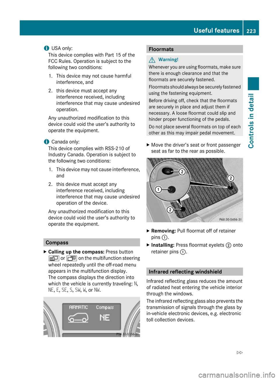
XMove the driver’s seat or front passenger
seat as far to the rear as possible.
XRemoving: Pull floormat off of retainer
pins :.
XInstalling: Press floormat eyelets ; onto
retainer pins :.
Infrared reflecting windshield
Infrared reflecting glass reduces the amount
of radiated heat entering the vehicle interior
through the windows.
The infrared reflecting glass also prevents the
transmission of signals through the glass by
in-vehicle electronic devices, e.g. electronic
toll collection devices.
Useful features223Controls in detailX164_AKB; 5; 31, en-USd2ureepe,Version: 2.11.8.12009-09-11T12:30:16+02:00 - Seite 223Z
Page 236 of 380
Important guidelines
R Only use sets of tires and rims of the same
type and make.
R Tires must be of the correct size for the rim.
R Break in new tires for approximately
60 miles (100 km) at moderate speeds.
R Regularly check the tires and rims for
damage. Dented or bent rims can cause tire
inflation pressure loss and damage to the
tire beads.
R If the vehicle is heavily loaded, check tire
inflation pressure and correct as required.
R Do not allow your tires to wear down too
far. Adhesion properties on wet roads are
sharply reduced at tread depths of less
than 1
/ 8 in (3 mm).
R When replacing individual tires, you should
mount new tires on the front wheels first
(on vehicles with same-sized wheels all
around).
Recommended tire inflation pressure
GWarning!
Follow recommended tire inflation pressures.
Do not underinflate tires. Underinflated tires
wear excessively and/or unevenly, adversely
affect handling and fuel economy, and are
more likely to fail from being overheated.
Do not overinflate tires. Overinflated tires can
adversely affect handling and ride comfort,
wear unevenly, increase stopping distance,
and result in sudden deflation (blowout)
because they are more likely to become
punctured or damaged by road debris,
potholes etc.
Do not overload the tires by exceeding the
specified load limit as indicated on the Tire
and Loading Information placard on the
driver’s door B-pillar. Overloading the tires
can overheat them, possibly causing a
blowout. Overloading the tires can also result
in handling or steering problems, or brake
failure.
Your vehicle is equipped with the Tire and
Loading Information placard located on the
driver’s door B-pillar ( Y page 242).
The tire inflation pressure should be checked
regularly. Only adjust the tire inflation
pressure on cold tires. The tires can be
considered cold if the vehicle has been
parked for at least 3 hours or driven less than
1 mile (1.6 km). Depending on the ambient
temperature, the driving speed and the tire
load, the tire temperature changes. When the
tire temperature changes by 18 ‡ (10†), the
tire inflation pressure will change by
approximately 1.5 psi (0.1 bar). Keep this in
mind when checking tire inflation pressure on
warm tires and adjust the tire pressure only
if the tire inflation pressure is too low for the
current operating conditions. If you check the
tire inflation pressure when the tires are
warm, the reading will be higher than the cold
reading. This is normal. Do not let air out to
match the specified cold tire inflation
pressure. Otherwise, the tire will be
underinflated.
Follow recommended cold tire inflation
pressures listed on Tire and Loading
Information placard on the driver’s door
B-pillar.
Keeping the tires properly inflated provides
the best handling, tread life and riding
comfort.
In addition to the Tire and Loading
Information placard on the driver’s door
B-pillar, also consult the tire inflation
pressure label on the inside of the filler flap
for any additional information pertaining to
special driving situations. For more
information, see “Important notes on tire
inflation pressure” ( Y page 235).
i Data shown on Tire and Loading
Information placard example are for
illustration purposes only. Tire data are
specific to each vehicle and may vary from234Tires and wheelsOperation
X164_AKB; 5; 31, en-USd2ureepe,Version: 2.11.8.12009-09-11T12:30:16+02:00 - Seite 234
Page 237 of 380
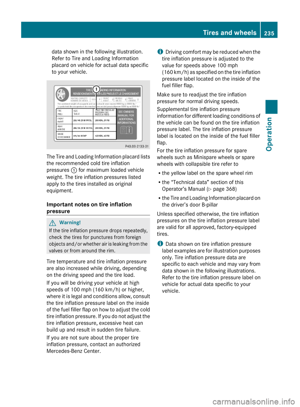
data shown in the following illustration.
Refer to Tire and Loading Information
placard on vehicle for actual data specific
to your vehicle.
The Tire and Loading Information placard lists
the recommended cold tire inflation
pressures : for maximum loaded vehicle
weight. The tire inflation pressures listed
apply to the tires installed as original
equipment.
Important notes on tire inflation
pressure
GWarning!
If the tire inflation pressure drops repeatedly,
check the tires for punctures from foreign
objects and/or whether air is leaking from the
valves or from around the rim.
Tire temperature and tire inflation pressure
are also increased while driving, depending
on the driving speed and the tire load.
If you will be driving your vehicle at high
speeds of 100 mph (160 km/h) or higher,
where it is legal and conditions allow, consult
the tire inflation pressure label on the inside
of the fuel filler flap on how to adjust the cold
tire inflation pressure. If you do not adjust the
tire inflation pressure, excessive heat can
build up and result in sudden tire failure.
If you are not sure about the proper tire
inflation pressure, contact an authorized
Mercedes-Benz Center.
iDriving comfort may be reduced when the
tire inflation pressure is adjusted to the
value for speeds above 100 mph
(160 km/h) as specified on the tire inflation
pressure label located on the inside of the
fuel filler flap.
Make sure to readjust the tire inflation
pressure for normal driving speeds.
Supplemental tire inflation pressure
information for different loading conditions of
the vehicle can be found on the tire inflation
pressure label. The tire inflation pressure
label is located on the inside of the fuel filler
flap.
For the tire inflation pressure for spare
wheels such as Minispare wheels or spare
wheels with collapsible tire refer to
Rthe yellow label on the spare wheel rim
Rthe “Technical data” section of this
Operator’s Manual (Y page 368)
Rthe Tire and Loading Information placard on
the driver’s door B-pillar
Unless specified otherwise, the tire inflation
pressures on the tire inflation pressure label
are valid for all approved, factory-equipped
tires.
iData shown on tire inflation pressure
label examples are for illustration purposes
only. Tire inflation pressure data are
specific to each vehicle and may vary from
data shown in the following illustrations.
Refer to the tire inflation pressure label on
vehicle for actual data specific to your
vehicle.
Tires and wheels235OperationX164_AKB; 5; 31, en-USd2ureepe,Version: 2.11.8.12009-09-11T12:30:16+02:00 - Seite 235Z
Page 242 of 380
illuminated, the system may not be able to
detect or signal low tire pressure as intended.
TPMS malfunctions may occur for a variety of
reasons, including the installation of
incompatible replacement or alternate tires
or wheels on the vehicle that prevent the
TPMS from functioning properly. Always
check the TPMS malfunction telltale after
replacing one or more tires or wheels on your
vehicle to ensure that the replacement or
alternate tires and wheels allow the TPMS to
continue to function properly.
iIf a condition causing the TPMS to
malfunction develops, it may take up to
10 minutes for the system to signal a
malfunction using the TPMS telltale
flashing and illumination sequence.
The telltale extinguishes after a few
minutes driving if the malfunction has been
corrected.
Tire pressure inquiries are made using the
multifunction display. The current tire
inflation pressure for each tire appears in the
multifunction display after a few minutes of
driving.
iPossible differences between the
readings of a tire pressure gauge of an air
hose, e.g. gas station equipment, and the
vehicle’s control system can occur. The tire
pressure displayed by the control system
apply to sea level. In high-altitude
locations, the reading on a tire pressure
gauge will be higher than the reading issued
by the vehicle’s control system. Do not
reduce the tire inflation pressure under
such circumstances.
XSwitch on the ignition.XPress button V or U on the
multifunction steering wheel repeatedly
until the standard display appears in the
multifunction display (Y page 128).
XPress button & or * until the current
inflation pressure for each tire appears in
the multifunction display.
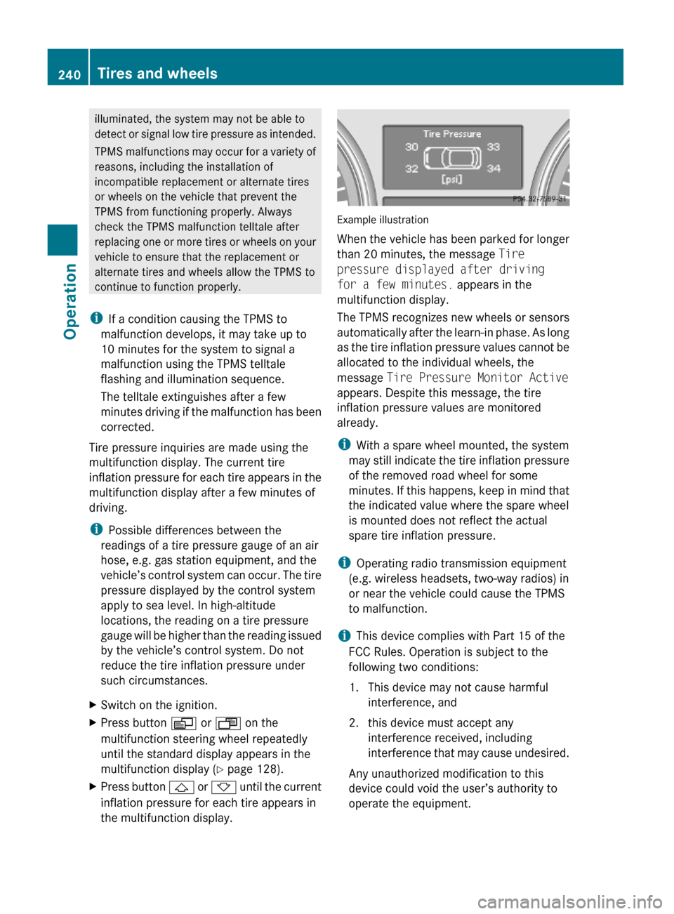
Example illustration
When the vehicle has been parked for longer
than 20 minutes, the message Tire
pressure displayed after driving
for a few minutes. appears in the
multifunction display.
The TPMS recognizes new wheels or sensors
automatically after the learn-in phase. As long
as the tire inflation pressure values cannot be
allocated to the individual wheels, the
message Tire Pressure Monitor Active
appears. Despite this message, the tire
inflation pressure values are monitored
already.
iWith a spare wheel mounted, the system
may still indicate the tire inflation pressure
of the removed road wheel for some
minutes. If this happens, keep in mind that
the indicated value where the spare wheel
is mounted does not reflect the actual
spare tire inflation pressure.
iOperating radio transmission equipment
(e.g. wireless headsets, two-way radios) in
or near the vehicle could cause the TPMS
to malfunction.
iThis device complies with Part 15 of the
FCC Rules. Operation is subject to the
following two conditions:
1. This device may not cause harmful
interference, and
2. this device must accept any
interference received, including
interference that may cause undesired.
Any unauthorized modification to this
device could void the user’s authority to
operate the equipment.
240Tires and wheelsOperation
X164_AKB; 5; 31, en-USd2ureepe,Version: 2.11.8.12009-09-11T12:30:16+02:00 - Seite 240
Page 257 of 380
radio, and heater, to the extent that these
items are available as factory-installed
equipment (whether installed or not).
Air pressure
The amount of air inside the tire pressing
outward on each square inch of the tire. Air
pressure is expressed in pounds per square
inch (psi), kilopascal (kPa), or bar.
Aspect ratio
Dimensional relationship between tire
section height and section width expressed
in percentage.
Bar
Metric unit for air pressure. There are
14.5038 pounds per square inch (psi) to
1 bar; there are 100 kilopascals (kPa) to 1 bar.
Bead
The tire bead contains steel wires wrapped by
steel cords that hold the tire onto the rim.
Cold tire inflation pressure
Tire inflation pressure when your vehicle has
been sitting for at least 3 hours or driven no
more than 1 mile (1.6 km).
Curb weight
The weight of a motor vehicle with standard
equipment including the maximum capacity
of fuel, oil, and coolant, and, if so equipped,
air conditioning and additional optional
equipment, but without passengers and
cargo.
DOT (Department of Transportation)
A tire branding symbol which denotes the tire
meets requirements of the U.S. Department
of Transportation.
GAWR (Gross Axle Weight Rating)
The GAWR is the maximum permissible axle
weight. The gross vehicle weight on each axle
must never exceed the GAWR for the front
and rear axle indicated on the certification
label located on the driver’s door B-pillar.
GTW (Gross Trailer Weight)
The GTW is the weight of the trailer plus the
weight of all cargo, equipment, luggage etc.
loaded on the trailer.
GVW (Gross Vehicle Weight)
The GVW comprises the weight of the vehicle
including fuel, tools, spare wheel, installed
accessories, passengers and cargo and, if
applicable, trailer tongue load. The GVW must
never exceed the GVWR indicated on the
certification label located on the driver’s door
B-pillar.
GVWR (Gross Vehicle Weight Rating)
This is the maximum permissible vehicle
weight of the fully loaded vehicle (weight of
the vehicle including all options, passengers,
fuel, and cargo and, if applicable, trailer
tongue load). It is indicated on the
certification label located on the driver’s door
B-pillar.
Kilopascal (kPa)
Metric unit for air pressure. There are 6.9 kPa
to 1 psi; another metric unit for air pressure
is bar. There are 100 kilopascals (kPa) to
1 bar.
Load index
Numerical code associated with the
maximum load a tire can support.
Maximum load rating
The maximum load in kilograms and pounds
that can be carried by the tire.
Tires and wheels255OperationX164_AKB; 5; 31, en-USd2ureepe,Version: 2.11.8.12009-09-11T12:30:16+02:00 - Seite 255Z
Page 258 of 380
Maximum loaded vehicle weight
The sum of curb weight, accessory weight,
total load limit, and production options
weight.
Maximum permissible tire inflation
pressure
This number is the greatest amount of air
pressure that should ever be put in the tire.
Normal occupant weight
The number of occupants the vehicle is
designed to seat, multiplied by 68 kilograms
(150 lb).
Occupant distribution
The distribution of occupants in a vehicle at
their designated seating positions.
Production options weight
The combined weight of those installed
regular production options weighing over
5 lbs (2.3 kilograms) in excess of those
standard items which they replace, not
previously considered in curb weight or
accessory weight, including heavy duty
brakes, ride levelers, roof rack, heavy duty
battery, and special trim.
PSI (Pounds per square inch)
A standard unit of measure for air pressure.
Recommended tire inflation pressure
The recommended tire inflation pressure for
normal driving conditions is listed on the Tire
and Loading Information placard located on
the driver’s door B-pillar. It provides best
handling, tread life and riding comfort.
Supplemental information pertaining to
special driving situations can be found on the
tire inflation pressure label on the inside of
the fuel filler flap.
Rim
A metal support for a tire or a tire and tube
assembly upon which the tire beads are
seated.
Sidewall
The portion of a tire between the tread and
the bead.
TIN (Tire Identification Number)
Unique identifier which facilitates efforts by
tire manufacturers to notify purchasers in
recall situations or other safety matters
concerning tires and gives purchasers the
means to easily identify such tires. The TIN is
comprised of “Manufacturer’s identification
mark”, “Tire size”, “Tire type code” and “Date
of manufacture”.
Tire ply composition and material used
This indicates the number of plies or the
number of layers of rubber-coated fabric in
the tire tread and sidewall. Tire
manufacturers also must indicate the ply
materials in the tire and sidewall, which
include steel, nylon, polyester, and others.
Tire speed rating
Part of tire designation (speed symbol);
indicates the speed range for which a tire is
approved.
Total load limit
Rated cargo and luggage load plus
68 kilograms (150 lb) times the vehicle’s
designated seating capacity.
Traction
The adhesive friction of a tire on a surface on
which it moves. The amount of grip provided.
256Tires and wheelsOperation
X164_AKB; 5; 31, en-USd2ureepe,Version: 2.11.8.12009-09-11T12:30:16+02:00 - Seite 256