2010 MERCEDES-BENZ GL450 ELECTRICAL
[x] Cancel search: ELECTRICALPage 274 of 380
vehicle and/or opens or closes doors or the
tailgate.
The vehicle’s level could change and you
could endanger yourself and/or others as a
result.
Make sure that you do not operate the ADS
button or the vehicle level control system
when coupling/decoupling the trailer.XMake sure the automatic transmission is in
park position P (Y page 115).XEngage the parking brake for the vehicle
( Y page 112).XStart the engine ( Y page 108).XClose all doors and the tailgate.XEngage the parking brake for the trailer.GWarning!
As soon as you disconnect the electrical
connection between the trailer and the
vehicle, the vehicle will lower. To help avoid
personal injury, make sure no one is near the
wheel housing or underneath the vehicle
before the electrical connection is
disconnected.
When you decouple the trailer, the vehicle is
temporarily raised because the springs are
relieved of load. Be especially careful during
this process, as you could otherwise injure
yourself and/or others. Make sure that any
persons remaining in the vehicle do not press
the switches for vehicle level control or the
ADS.
XDisconnect all electrical plug connectors.XDecouple the trailer.XMake sure that the trailer coupling is free
of load.XTurn off the engine ( Y page 113).
Driving abroad
If you plan to drive the vehicle outside the U.S.
or Canada, you should request dealer
network information for your destination from
any authorized Mercedes-Benz Center.
Control and operation of radio
transmitter
Safety notes
GWarning!
Please do not forget that your primary
responsibility is to drive the vehicle. A driver’s
attention to the road must always be his/her
primary focus when driving. For your safety
and the safety of others, we recommend that
you pull over to a safe location and stop
before placing or taking a telephone call.
If you choose to use the telephone 18
while
driving, please use the hands-free device and
only use the telephone when road, weather
and traffic conditions permit. Some
jurisdictions prohibit the driver from using a
mobile telephone while driving a vehicle.
Only operate the COMAND 18
(Cockpit
Management and Data System) if road,
weather and traffic conditions permit.
Otherwise, you may not be able to observe
traffic conditions and could endanger yourself
and others.
Bear in mind that at a speed of just 30 mph
(approximately 50 km/h), your vehicle is
covering a distance of 44 feet (approximately
14 m) every second.
Emission control
Certain systems of the engine serve to keep
the toxic components of the exhaust gases
within permissible limits required by law.
These systems will function properly only
when maintained strictly according to factory
specifications. Any adjustments on the
engine should, therefore, be carried out only
by qualified Mercedes-Benz Center
authorized technicians.
18 Observe all legal requirements.272Driving instructionsOperation
X164_AKB; 5; 31, en-USd2ureepe,Version: 2.11.8.12009-09-11T12:30:16+02:00 - Seite 272
Page 278 of 380
here. In such cases it is best to seek aid at an
authorized Mercedes-Benz Center.
The following topics deal with the cleaning
and care of your vehicle and give important
“how-to” information as well as references to
Mercedes-Benz approved vehicle-care
products.
Power washer
! Follow the instructions provided by the
power washer manufacturer on
maintaining a distance between the vehicle
and the nozzle of the power washer.
Never use a round nozzle to power-wash
tires. The intense jet of water can result in
damage to the tire.
Always replace a damaged tire.
Always keep the jet of water moving across
the surface. Do not aim directly at electrical
parts, electrical connectors, seals, or other
rubber parts.
i Vehicles with KEYLESS-GO:
If a door handle is hit by a strong jet of
water, and a SmartKey is within
approximately 3 ft (1 m) of the vehicle, it
could be inadvertently locked or unlocked.
Tar stains
Quickly remove tar stains before they dry and
become more difficult to remove. A tar
remover is recommended.
Paintwork, painted body components
! Affixing stickers, magnets, adhesive tape
or similar materials to painted body
components may damage the paintwork.
Mercedes-Benz approved Paint Care should
be applied when water drops on the paint
surface do not “bead up”. This should
normally be done every 3 to 5 months,
depending on the climate and washing
detergent used.
Mercedes-Benz approved Paint Cleaner
should be applied if the paint surface shows
signs of embedded dirt (i.e. loss of gloss).
Do not apply any of these products or wax if
your vehicle is parked in the sun or if the hood
is still hot.XUse the appropriate MB-Touch-Up Stick for
quick and provisional repairs of minor paint
damage (i.e. chips from stones, vehicle
doors, etc.).
Engine cleaning
Prior to cleaning the engine compartment,
make sure to protect electrical components
and connectors from contact with water and
cleaning agents.
Corrosion protection, such as MB
Anticorrosion Wax should be applied to the
engine compartment after every engine
cleaning. Before applying, all control linkage
bushings and joints should be lubricated. The
poly-V-belt and all pulleys should be
protected from any wax.
Vehicle washing
In the winter, thoroughly remove all traces of
road salt as soon as possible.
When washing the vehicle underbody, do not
forget to clean the inner sides of the wheels.
i Vehicles with KEYLESS-GO:
If a door handle is hit by a strong jet of
water, and a SmartKey is within
approximately 3 ft (1 m) of the vehicle, it
could be inadvertently locked or unlocked.
Hand-wash
XDo not use hot water or wash your vehicle
in direct sunlight.XOnly use a soft, wet cloth or sponge to
clean the vehicle.XOnly use a mild vehicle wash detergent,
such as Mercedes-Benz approved Car
Shampoo.276Vehicle careOperation
X164_AKB; 5; 31, en-USd2ureepe,Version: 2.11.8.12009-09-11T12:30:16+02:00 - Seite 276
Page 340 of 380
iIf sealant has leaked out, let it dry. You
can then peel it off.
If clothing has come in contact with
TIREFIT, have it dry-cleaned with
perchloroethylene as soon as possible.
GWarning!
Observe safety instructions on air pump label.
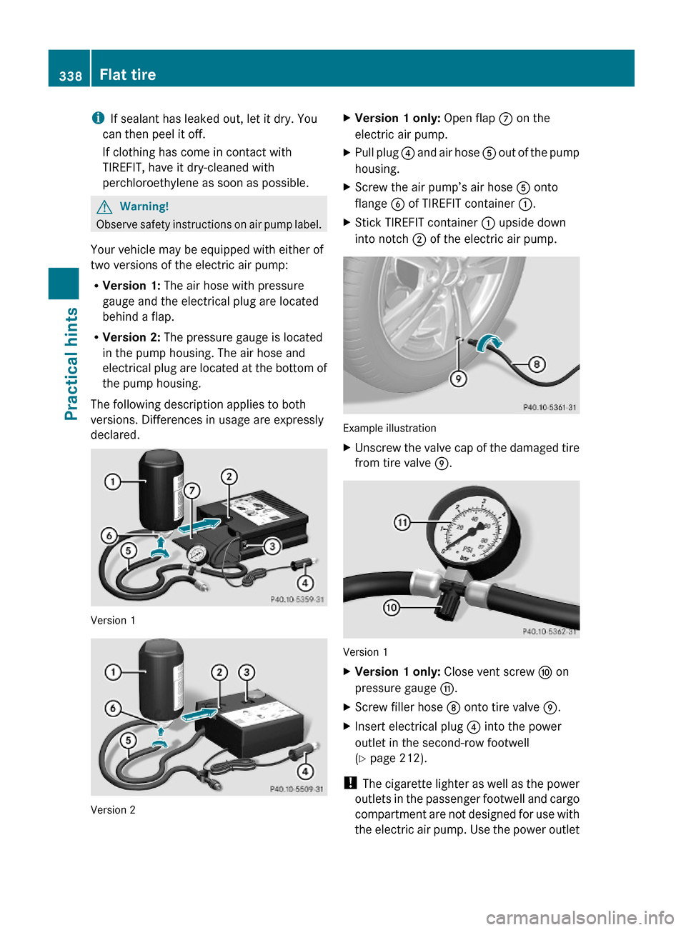
Your vehicle may be equipped with either of
two versions of the electric air pump:
RVersion 1: The air hose with pressure
gauge and the electrical plug are located
behind a flap.
RVersion 2: The pressure gauge is located
in the pump housing. The air hose and
electrical plug are located at the bottom of
the pump housing.
The following description applies to both
versions. Differences in usage are expressly
declared.
Version 1
Version 2
XVersion 1 only: Open flap C on the
electric air pump.
XPull plug ? and air hose A out of the pump
housing.
XScrew the air pump’s air hose A onto
flange B of TIREFIT container :.
XStick TIREFIT container : upside down
into notch ; of the electric air pump.
Example illustration
XUnscrew the valve cap of the damaged tire
from tire valve E.
Version 1
XVersion 1 only: Close vent screw F on
pressure gauge G.
XScrew filler hose D onto tire valve E.XInsert electrical plug ? into the power
outlet in the second-row footwell
(Y page 212).
! The cigarette lighter as well as the power
outlets in the passenger footwell and cargo
compartment are not designed for use with
the electric air pump. Use the power outlet
338Flat tirePractical hints
X164_AKB; 5; 31, en-USd2ureepe,Version: 2.11.8.12009-09-11T12:30:16+02:00 - Seite 338
Page 353 of 380
Never lean over batteries while connecting or
jump starting. You might get injured.
Battery fluid contains sulfuric acid. Do not
allow this fluid to come in contact with eyes,
skin or clothing. In case it does, immediately
flush affected area with water, and seek
medical help if necessary.
A battery will also produce hydrogen gas,
which is flammable and explosive. Keep
flames or sparks away from battery, avoid
improper connection of jumper cables,
smoking, etc.
Attempting to jump start a frozen battery can
result in it exploding, causing personal injury.
Read all instructions before proceeding.
! Do not tow-start the vehicle. You could
otherwise seriously damage the automatic
transmission which is not covered by the
Mercedes-Benz Limited Warranty.
! Jump starting should only be performed
using the jump-start terminals located in
the engine compartment.
Avoid repeated and lengthy starting
attempts.
Do not attempt to start the engine using a
battery quick-charge unit.
If the engine does not run after several
unsuccessful starting attempts, have it
checked at the nearest authorized
Mercedes-Benz Center.
Excessive unburned fuel generated by
repeated failed starting attempts may
damage the catalytic converter 20
and may
present a fire risk.
Make sure the jumper cables do not have
loose or missing insulation.
Make sure the cable clamps do not touch
any other metal part while the other end is
still attached to a battery.If the battery is discharged, the engine can be
started with jumper cables and the fully
charged battery of another vehicle or an
equivalent starter pack. Observe the
following:
R Access to the battery is not possible on all
vehicles. If you cannot access the battery
of the other vehicle, provide jump start
power by an external battery or starter
pack.
R Jump starting should only be performed
when the engine and catalytic converter 21
are cold.
R Do not start the engine if the battery is
frozen. Let the battery thaw out first.
R Only jump start from batteries with the
same voltage rating (12 V). Jump starting
with a more powerful battery could damage
the vehicle’s electrical system. Such
damage will not be covered by the
Mercedes-Benz Limited Warranty.
R Only use jumper cables with sufficient
cross-section and insulated terminal
clamps.
R Always make sure the jumper cables are
not on or near pulleys, fans or other parts
that move when an engine is started or
running.
R Should the battery be drained completely,
let the donating power source charge the
vehicle for several minutes before
reattempting the starting process.
The jump-start contacts are located in the
engine compartment on the passenger side.XMake sure the two vehicles do not touch.XSwitch off all electrical consumers.XEngage the parking brake.XMake sure the automatic transmission is in
park position P.XOpen the hood ( Y page 228).20
Vehicles with gasoline engine only.
21 Vehicles with gasoline engine only.Jump starting351Practical hintsX164_AKB; 5; 31, en-USd2ureepe,Version: 2.11.8.12009-09-11T12:30:16+02:00 - Seite 351Z
Page 354 of 380

Position C represents the charged battery of
another vehicle or an equivalent starter pack.
XFlip up cover : of positive terminal = in
direction of arrow.
! Never invert the terminal connections!
XConnect positive terminal ; of charged
battery C with positive terminal = with a
jumper cable. Clamp the cable to positive
terminal ; of charged battery C first.
XStart engine of the vehicle with charged
battery C and run at idle speed.
XSlide cover A from negative terminal B in
direction of arrow.
XConnect negative terminal ? of charged
battery C with negative terminal B with
a jumper cable. Clamp the cable to
negative terminal ? of charged battery
C first.
XStart engine of the vehicle with the
discharged battery and run at idle speed.
You can now turn on the electrical
consumers. Do not switch on the
headlamps under any circumstances.
XRemove the jumper cables from negative
terminals ? and B first.
XRemove the jumper cables from positive
terminals ; and =.
You can now switch on the headlamps.
XClose cover : of positive terminal =.XSlide cover A back onto negative terminal
B.
XHave the battery checked at the nearest
authorized Mercedes-Benz Center.
Towing the vehicle
Safety notes
Mercedes-Benz recommends that the vehicle
be transported with all wheels off the ground
using flatbed or appropriate wheel lift/dolly
equipment. This method is preferable to other
types of towing.
! To prevent damage during transport, do
not tie down vehicle by its chassis or
suspension parts.
If circumstances do not permit the
recommended towing methods, the vehicle
352Towing the vehiclePractical hints
X164_AKB; 5; 31, en-USd2ureepe,Version: 2.11.8.12009-09-11T12:30:16+02:00 - Seite 352
Page 356 of 380
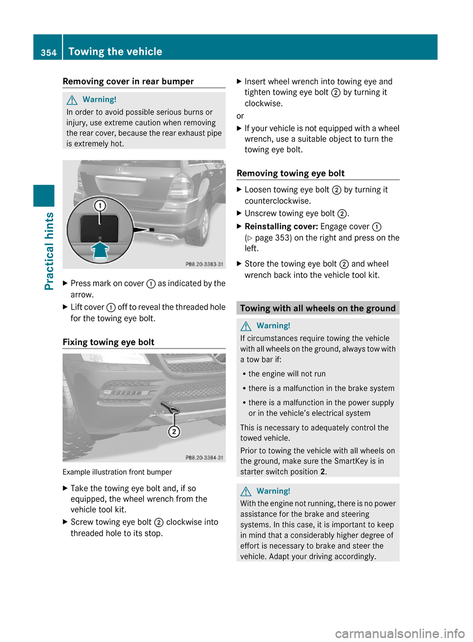
Removing cover in rear bumperGWarning!
In order to avoid possible serious burns or
injury, use extreme caution when removing
the rear cover, because the rear exhaust pipe
is extremely hot.
XPress mark on cover : as indicated by the
arrow.
XLift cover : off to reveal the threaded hole
for the towing eye bolt.
Fixing towing eye bolt
Example illustration front bumper
XTake the towing eye bolt and, if so
equipped, the wheel wrench from the
vehicle tool kit.
XScrew towing eye bolt ; clockwise into
threaded hole to its stop.
XInsert wheel wrench into towing eye and
tighten towing eye bolt ; by turning it
clockwise.
or
XIf your vehicle is not equipped with a wheel
wrench, use a suitable object to turn the
towing eye bolt.
Removing towing eye bolt
XLoosen towing eye bolt ; by turning it
counterclockwise.
XUnscrew towing eye bolt ;.XReinstalling cover: Engage cover :
(Y page 353) on the right and press on the
left.
XStore the towing eye bolt ; and wheel
wrench back into the vehicle tool kit.
Towing with all wheels on the ground
GWarning!
If circumstances require towing the vehicle
with all wheels on the ground, always tow with
a tow bar if:
Rthe engine will not run
Rthere is a malfunction in the brake system
Rthere is a malfunction in the power supply
or in the vehicle’s electrical system
This is necessary to adequately control the
towed vehicle.
Prior to towing the vehicle with all wheels on
the ground, make sure the SmartKey is in
starter switch position 2.
GWarning!
With the engine not running, there is no power
assistance for the brake and steering
systems. In this case, it is important to keep
in mind that a considerably higher degree of
effort is necessary to brake and steer the
vehicle. Adapt your driving accordingly.
354Towing the vehiclePractical hints
X164_AKB; 5; 31, en-USd2ureepe,Version: 2.11.8.12009-09-11T12:30:16+02:00 - Seite 354
Page 357 of 380
XMake sure the ignition is switched on.XWith the vehicle at a standstill, depress the
brake pedal and keep it pressed.XShift the automatic transmission into
neutral position N.XRelease the brake pedal.XIf engaged, release the parking brake.XSwitch on the hazard warning flasher
( Y page 101).
!
Keep in mind that it is important to have
the ignition switched on. Removing the
SmartKey from the starter switch or
opening a front door with the ignition
switched off will automatically shift the
automatic transmission into park position
P .
! The vehicle may be towed only for
distances up to 30 miles (50 km) and at a
speed not to exceed 30 mph (50 km/h).
i While being towed with the hazard
warning flasher in use, use the combination
switch in the usual manner to signal turns.
Only the selected turn signal will operate.
Upon canceling the turn signal, the hazard
warning flasher will operate again.
Stranded vehicle
Freeing a stranded vehicle, on which the
wheels are dug into sand or mud, should be
done with the greatest of care, especially if
the vehicle is heavily loaded.
Note the following when freeing a stranded
vehicle:
R Avoid pulling the vehicle abruptly or
diagonally, since it could result in damage
to the chassis alignment.
R Never try to free a vehicle that is still
coupled to a trailer.
R If possible, a vehicle equipped with a trailer
hitch receiver should be pulled backward in
its own previously made tracks.
Fuses
Introduction
The electrical fuses in your vehicle serve to
switch off malfunctioning power circuits.
If a fuse is blown, the components and
systems secured by that fuse will stop
operating.
GWarning!
Only use fuses approved by Mercedes-Benz
with the specified amperage for the system in
question and do not attempt to repair or
bridge a blown fuse. Using other than
approved fuses or using repaired or bridged
fuses may cause an overload leading to a fire,
and/or cause damage to electrical
components and/or systems. Have the cause
determined and remedied by an authorized
Mercedes-Benz Center.
A blown fuse must be replaced by an
appropriate spare fuse (recognizable by its
color or the fuse rating given on the fuse) of
the amperage recommended in the fuse
chart. Any Mercedes-Benz Center will be glad
to advise you on this subject.
i In case of a blown fuse contact Roadside
Assistance or an authorized Mercedes-
Benz Center.
If a newly inserted fuse blows again, have the
cause determined and rectified by an
authorized Mercedes-Benz Center.
The fuse chart is located in the cargo
compartment with the vehicle tool kit
( Y page 284). The fuse chart explains the fuse
allocation and fuse amperages.
Before replacing fuses
XEngage the parking brake.XMake sure the automatic transmission is in
park position P.
The transmission position indicator in the
multifunction display should be on P.XSwitch off all electrical consumers.Fuses355Practical hintsX164_AKB; 5; 31, en-USd2ureepe,Version: 2.11.8.12009-09-11T12:30:16+02:00 - Seite 355Z
Page 364 of 380
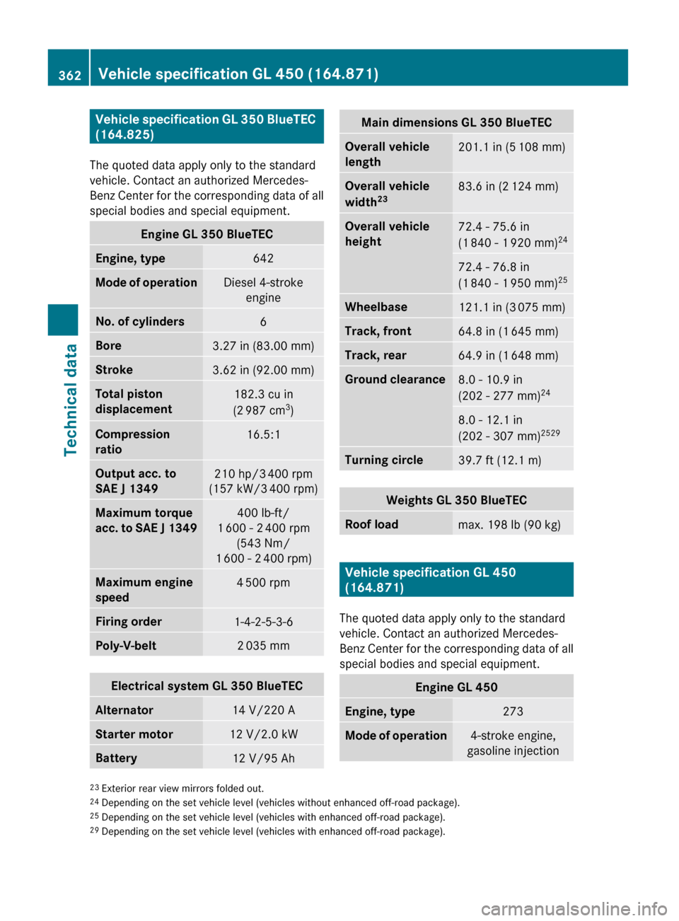
Vehicle specification GL 350 BlueTEC
(164.825)
The quoted data apply only to the standard
vehicle. Contact an authorized Mercedes-
Benz Center for the corresponding data of all
special bodies and special equipment.Engine GL 350 BlueTECEngine, type642Mode of operationDiesel 4-stroke engineNo. of cylinders6Bore3.27 in (83.00 mm)Stroke3.62 in (92.00 mm)Total piston
displacement182.3 cu in
(2 987 cm 3
)Compression
ratio16.5:1Output acc. to
SAE J 1349210 hp/3 400 rpm
(157 kW/3 400 rpm)Maximum torque
acc. to SAE J 1349400 lb-ft/
1 600 - 2 400 rpm
(543 Nm/
1 600 - 2 400 rpm)Maximum engine
speed4 500 rpmFiring order1-4-2-5-3-6Poly-V-belt2 035 mmElectrical system GL 350 BlueTECAlternator14 V/220 AStarter motor12 V/2.0 kWBattery12 V/95 AhMain dimensions GL 350 BlueTECOverall vehicle
length201.1 in (5 108 mm)Overall vehicle
width 2383.6 in (2
124 mm)Overall vehicle
height72.4 - 75.6 in
(1 840 - 1 920 mm) 2472.4 - 76.8 in
(1 840 - 1 950 mm) 25Wheelbase121.1 in (3
075 mm)Track, front64.8 in (1 645 mm)Track, rear64.9 in (1 648 mm)Ground clearance8.0 - 10.9 in
(202 - 277 mm) 248.0 - 12.1 in
(202 - 307 mm) 2529Turning circle39.7 ft (12.1 m)Weights GL 350 BlueTECRoof loadmax. 198 lb (90 kg)
Vehicle specification GL 450
(164.871)
The quoted data apply only to the standard
vehicle. Contact an authorized Mercedes-
Benz Center for the corresponding data of all
special bodies and special equipment.
Engine GL 450Engine, type273Mode of operation4-stroke engine,
gasoline injection23 Exterior rear view mirrors folded out.
24 Depending on the set vehicle level (vehicles without enhanced off-road package).
25 Depending on the set vehicle level (vehicles with enhanced off-road package).
29 Depending on the set vehicle level (vehicles with enhanced off-road package).362Vehicle specification GL 450 (164.871)Technical data
X164_AKB; 5; 31, en-USd2ureepe,Version: 2.11.8.12009-09-11T12:30:16+02:00 - Seite 362