2010 MERCEDES-BENZ E63AMG weight
[x] Cancel search: weightPage 206 of 372
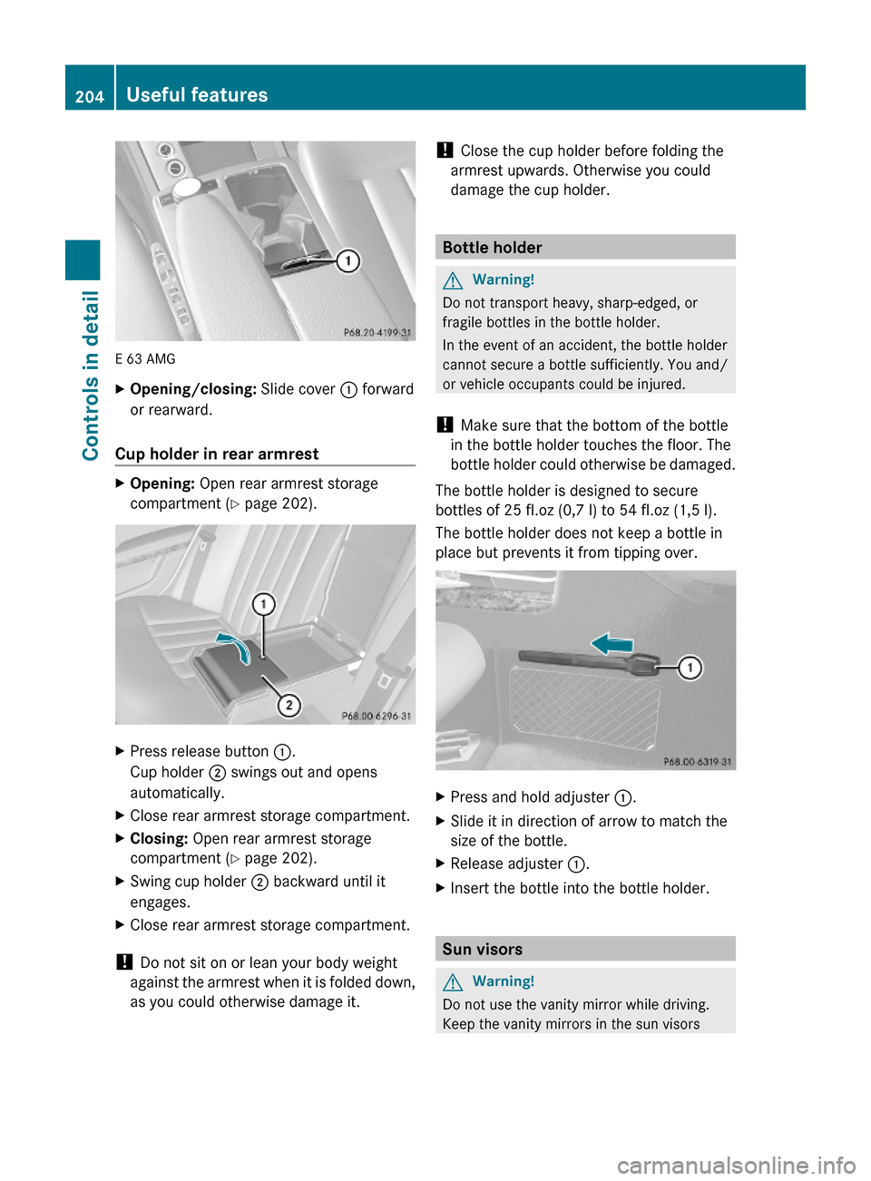
E 63 AMG
XOpening/closing: Slide cover : forward
or rearward.
Cup holder in rear armrest
XOpening: Open rear armrest storage
compartment (Y page 202).
XPress release button :.
Cup holder ; swings out and opens
automatically.
XClose rear armrest storage compartment.XClosing: Open rear armrest storage
compartment (Y page 202).
XSwing cup holder ; backward until it
engages.
XClose rear armrest storage compartment.
! Do not sit on or lean your body weight
against the armrest when it is folded down,
as you could otherwise damage it.
! Close the cup holder before folding the
armrest upwards. Otherwise you could
damage the cup holder.
Bottle holder
GWarning!
Do not transport heavy, sharp-edged, or
fragile bottles in the bottle holder.
In the event of an accident, the bottle holder
cannot secure a bottle sufficiently. You and/
or vehicle occupants could be injured.
! Make sure that the bottom of the bottle
in the bottle holder touches the floor. The
bottle holder could otherwise be damaged.
The bottle holder is designed to secure
bottles of 25 fl.oz (0,7 l) to 54 fl.oz (1,5 l).
The bottle holder does not keep a bottle in
place but prevents it from tipping over.
XPress and hold adjuster :.XSlide it in direction of arrow to match the
size of the bottle.
XRelease adjuster :.XInsert the bottle into the bottle holder.
Sun visors
GWarning!
Do not use the vanity mirror while driving.
Keep the vanity mirrors in the sun visors
204Useful featuresControls in detail
212_AKB; 2; 41, en-USd2ureepe,Version: 2.11.8.12009-07-17T09:14:21+02:00 - Seite 204
Page 231 of 372

Recommended tire inflation pressureGWarning!
Follow recommended tire inflation pressures.
Do not underinflate tires. Underinflated tires
wear excessively and/or unevenly, adversely
affect handling and fuel economy, and are
more likely to fail from being overheated.
Do not overinflate tires. Overinflated tires can
adversely affect handling and ride comfort,
wear unevenly, increase stopping distance,
and result in sudden deflation (blowout)
because they are more likely to become
punctured or damaged by road debris,
potholes etc.
Do not overload the tires by exceeding the
specified load limit as indicated on the Tire
and Loading Information placard on the
driver’s door B-pillar. Overloading the tires
can overheat them, possibly causing a
blowout. Overloading the tires can also result
in handling or steering problems, or brake
failure.
Your vehicle is equipped with the Tire and
Loading Information placard located on the
driver’s door B-pillar (Y page 237).
The tire inflation pressure should be checked
regularly. Only adjust the tire inflation
pressure on cold tires. The tires can be
considered cold if the vehicle has been
parked for at least 3 hours or driven less than
1 mile (1.6 km). Depending on the ambient
temperature, the driving speed and the tire
load, the tire temperature changes. When the
tire temperature changes by 18‡ (10†), the
tire inflation pressure will change by
approximately 1.5 psi (0.1 bar). Keep this in
mind when checking tire inflation pressure on
warm tires and adjust the tire pressure only
if the tire inflation pressure is too low for the
current operating conditions. If you check the
tire inflation pressure when the tires are
warm, the reading will be higher than the cold
reading. This is normal. Do not let air out to
match the specified cold tire inflation
pressure. Otherwise, the tire will be
underinflated.
Follow recommended cold tire inflation
pressures listed on Tire and Loading
Information placard on the driver’s door
B-pillar.
Keeping the tires properly inflated provides
the best handling, tread life and riding
comfort.
In addition to the Tire and Loading
Information placard on the driver’s door
B-pillar, also consult the tire inflation
pressure label on the inside of the filler flap
for any additional information pertaining to
special driving situations. For more
information, see “Important notes on tire
inflation pressure” (Y page 230).
iData shown on Tire and Loading
Information placard example are for
illustration purposes only. Tire data are
specific to each vehicle and may vary from
data shown in the following illustration.
Refer to Tire and Loading Information
placard on vehicle for actual data specific
to your vehicle.
The Tire and Loading Information placard lists
the recommended cold tire inflation
pressures : for maximum loaded vehicle
weight. The tire inflation pressures listed
apply to the tires installed as original
equipment.
Tires and wheels229Operation212_AKB; 2; 41, en-USd2ureepe,Version: 2.11.8.12009-07-17T09:14:21+02:00 - Seite 229Z
Page 239 of 372
may be displayed for the wrong position
temporarily. After driving for a few minutes,
the inflation pressure will be shown for the
correct position.
Maximum tire inflation pressure
GWarning!
Never exceed the maximum tire inflation
pressure. Follow recommended tire inflation
pressures.
Do not underinflate tires. Underinflated tires
wear excessively and/or unevenly, adversely
affect handling and fuel economy, and are
more likely to fail from being overheated.
Do not overinflate tires. Overinflated tires can
adversely affect handling and ride comfort,
wear unevenly, increase stopping distance,
and result in sudden deflation (blowout)
because they are more likely to become
punctured or damaged by road debris,
potholes etc.
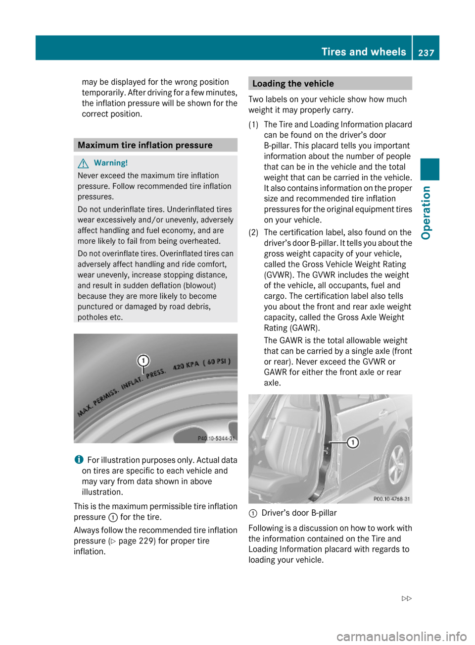
iFor illustration purposes only. Actual data
on tires are specific to each vehicle and
may vary from data shown in above
illustration.
This is the maximum permissible tire inflation
pressure : for the tire.
Always follow the recommended tire inflation
pressure (Y page 229) for proper tire
inflation.
Loading the vehicle
Two labels on your vehicle show how much
weight it may properly carry.
(1)The Tire and Loading Information placard
can be found on the driver’s door
B-pillar. This placard tells you important
information about the number of people
that can be in the vehicle and the total
weight that can be carried in the vehicle.
It also contains information on the proper
size and recommended tire inflation
pressures for the original equipment tires
on your vehicle.
(2)The certification label, also found on the
driver’s door B-pillar. It tells you about the
gross weight capacity of your vehicle,
called the Gross Vehicle Weight Rating
(GVWR). The GVWR includes the weight
of the vehicle, all occupants, fuel and
cargo. The certification label also tells
you about the front and rear axle weight
capacity, called the Gross Axle Weight
Rating (GAWR).
The GAWR is the total allowable weight
that can be carried by a single axle (front
or rear). Never exceed the GVWR or
GAWR for either the front axle or rear
axle.
:Driver’s door B-pillar
Following is a discussion on how to work with
the information contained on the Tire and
Loading Information placard with regards to
loading your vehicle.
Tires and wheels237Operation212_AKB; 2; 41, en-USd2ureepe,Version: 2.11.8.12009-07-17T09:14:21+02:00 - Seite 237Z
Page 240 of 372
Tire and Loading InformationGWarning!
Do not overload the tires by exceeding the
specified load limit as indicated on the Tire
and Loading Information placard on the
driver’s door B-pillar. Overloading the tires
can overheat them, possibly causing a
blowout. Overloading the tires can also result
in handling or steering problems, or brake
failure.
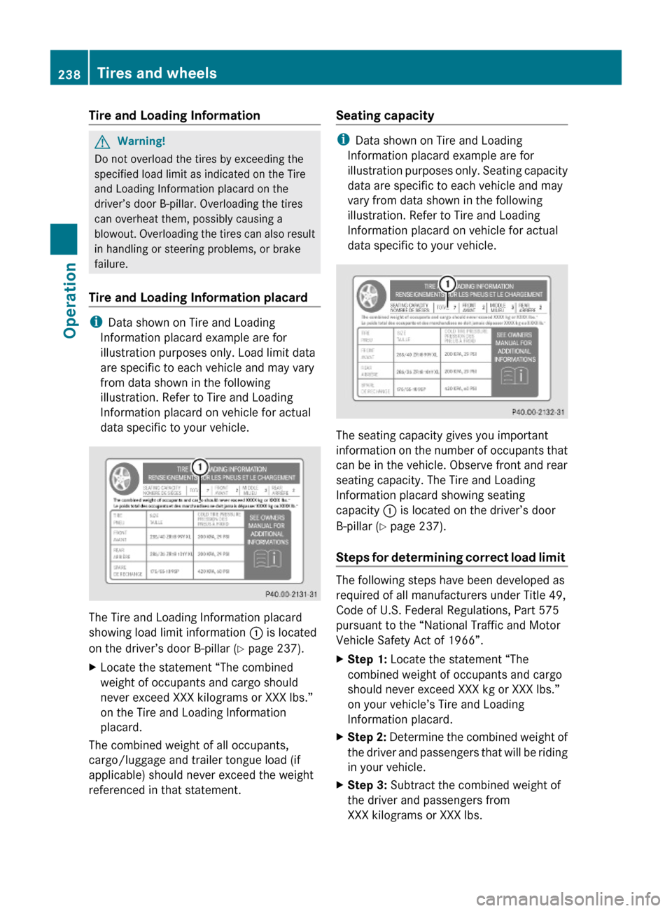
Tire and Loading Information placard
iData shown on Tire and Loading
Information placard example are for
illustration purposes only. Load limit data
are specific to each vehicle and may vary
from data shown in the following
illustration. Refer to Tire and Loading
Information placard on vehicle for actual
data specific to your vehicle.
The Tire and Loading Information placard
showing load limit information : is located
on the driver’s door B-pillar (Y page 237).
XLocate the statement “The combined
weight of occupants and cargo should
never exceed XXX kilograms or XXX lbs.”
on the Tire and Loading Information
placard.
The combined weight of all occupants,
cargo/luggage and trailer tongue load (if
applicable) should never exceed the weight
referenced in that statement.
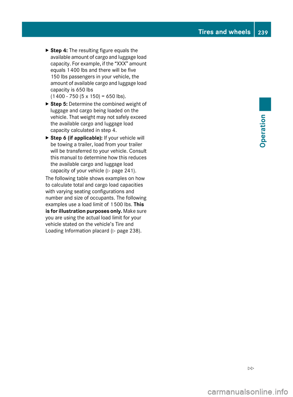
Seating capacity
iData shown on Tire and Loading
Information placard example are for
illustration purposes only. Seating capacity
data are specific to each vehicle and may
vary from data shown in the following
illustration. Refer to Tire and Loading
Information placard on vehicle for actual
data specific to your vehicle.
The seating capacity gives you important
information on the number of occupants that
can be in the vehicle. Observe front and rear
seating capacity. The Tire and Loading
Information placard showing seating
capacity : is located on the driver’s door
B-pillar (Y page 237).
Steps for determining correct load limit
The following steps have been developed as
required of all manufacturers under Title 49,
Code of U.S. Federal Regulations, Part 575
pursuant to the “National Traffic and Motor
Vehicle Safety Act of 1966”.
XStep 1: Locate the statement “The
combined weight of occupants and cargo
should never exceed XXX kg or XXX lbs.”
on your vehicle’s Tire and Loading
Information placard.
XStep 2: Determine the combined weight of
the driver and passengers that will be riding
in your vehicle.
XStep 3: Subtract the combined weight of
the driver and passengers from
XXX kilograms or XXX lbs.
238Tires and wheelsOperation
212_AKB; 2; 41, en-USd2ureepe,Version: 2.11.8.12009-07-17T09:14:21+02:00 - Seite 238
Page 241 of 372
XStep 4: The resulting figure equals the
available amount of cargo and luggage load
capacity. For example, if the “XXX” amount
equals 1 400 lbs and there will be five
150 lbs passengers in your vehicle, the
amount of available cargo and luggage load
capacity is 650 lbs
(1 400 - 750 (5 x 150) = 650 lbs).XStep 5: Determine the combined weight of
luggage and cargo being loaded on the
vehicle. That weight may not safely exceed
the available cargo and luggage load
capacity calculated in step 4.XStep 6 (if applicable): If your vehicle will
be towing a trailer, load from your trailer
will be transferred to your vehicle. Consult
this manual to determine how this reduces
the available cargo and luggage load
capacity of your vehicle ( Y page 241).
The following table shows examples on how
to calculate total and cargo load capacities
with varying seating configurations and
number and size of occupants. The following
examples use a load limit of 1 500 lbs. This
is for illustration purposes only. Make sure
you are using the actual load limit for your
vehicle stated on the vehicle’s Tire and
Loading Information placard ( Y page 238).
Tires and wheels239Operation212_AKB; 2; 41, en-USd2ureepe,Version: 2.11.8.12009-07-17T09:14:21+02:00 - Seite 239Z
Page 242 of 372
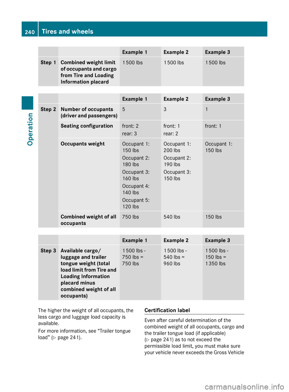
Example 1Example 2Example 3Step 1Combined weight limit
of occupants and cargo
from Tire and Loading
Information placard1 500 lbs1 500 lbs1 500 lbsExample 1Example 2Example 3Step 2Number of occupants
(driver and passengers)531Seating configurationfront: 2
rear: 3front: 1
rear: 2front: 1Occupants weightOccupant 1:
150 lbs
Occupant 2:
180 lbs
Occupant 3:
160 lbs
Occupant 4:
140 lbs
Occupant 5:
120 lbsOccupant 1:
200 lbs
Occupant 2:
190 lbs
Occupant 3:
150 lbsOccupant 1:
150 lbsCombined weight of all
occupants750 lbs540 lbs150 lbsExample 1Example 2Example 3Step 3Available cargo/
luggage and trailer
tongue weight (total
load limit from Tire and
Loading Information
placard minus
combined weight of all
occupants)1 500 lbs -
750 lbs =
750 lbs1 500 lbs -
540 lbs =
960 lbs1 500 lbs -
150 lbs =
1 350 lbsThe higher the weight of all occupants, the
less cargo and luggage load capacity is
available.
For more information, see “Trailer tongue
load” ( Y page 241).Certification label
Even after careful determination of the
combined weight of all occupants, cargo and
the trailer tongue load (if applicable)
( Y page 241) as to not exceed the
permissible load limit, you must make sure
your vehicle never exceeds the Gross Vehicle
240Tires and wheelsOperation
212_AKB; 2; 41, en-USd2ureepe,Version: 2.11.8.12009-07-17T09:14:21+02:00 - Seite 240
Page 243 of 372

Weight Rating (GVWR) and the Gross Axle
Weight Rating (GAWR) for either the front or
rear axle. You can obtain the GVWR and
GAWR from the certification label. The
certification label can be found on the driver’s
door B-pillar, see the “Technical data” section
(Y page 346).
Gross Vehicle Weight Rating (GVWR): The
total weight of the vehicle, all occupants, all
cargo, and the trailer tongue load (if
applicable) must never exceed the GVWR.
Gross Axle Weight Rating (GAWR): The total
allowable weight that can be carried by a
single axle (front or rear).
To assure that your vehicle does not exceed
the maximum permissible weight limits
(GVWR and GAWR for front and rear axle),
have the loaded vehicle (including driver,
passengers and all cargo and, if applicable,
trailer fully loaded) weighed on a suitable
commercial scale.
Trailer tongue load
The tongue load of any trailer is an important
weight to measure because it affects the load
you can carry in your vehicle. If a trailer is
towed, the tongue load must be added to the
weight of all occupants riding and any cargo
you are carrying in the vehicle. The tongue
load typically is 10% of the trailer weight and
everything loaded in it.
Your Mercedes-Benz has been designed
primarily to carry passengers and their cargo.
Mercedes-Benz does not recommend trailer
towing with your vehicle.
Maximum tire load
GWarning!
Do not overload the tires by exceeding the
specified load limit as indicated on the Tire
and Loading Information placard on the
driver’s door B-pillar. Overloading the tires
can overheat them, possibly causing a
blowout. Overloading the tires can also result
in handling or steering problems, or brake
failure.
iFor illustration purposes only. Actual data
on tires are specific to each vehicle and
may vary from data shown in above
illustration.
The maximum tire load rating : is the
maximum weight the tires are designed to
support.
For more information on tire load rating, see
(Y page 246).
For information on calculating total and cargo
load capacities, see (Y page 238).
Direction of rotation
Unidirectional tires offer added advantages,
such as better hydroplaning performance. To
benefit, however, you must make sure the
tires rotate in the direction specified.
An arrow on the sidewall indicates the
intended direction of rotation of the tire.
Spare wheels may be mounted against the
direction of rotation (spinning) even with a
unidirectional tire for temporary use only until
the regular drive wheel has been repaired or
replaced. Always observe and follow
applicable temporary use restrictions and
speed limitations indicated on the spare
wheel.
Tires and wheels241Operation212_AKB; 2; 41, en-USd2ureepe,Version: 2.11.8.12009-07-17T09:14:21+02:00 - Seite 241Z
Page 251 of 372
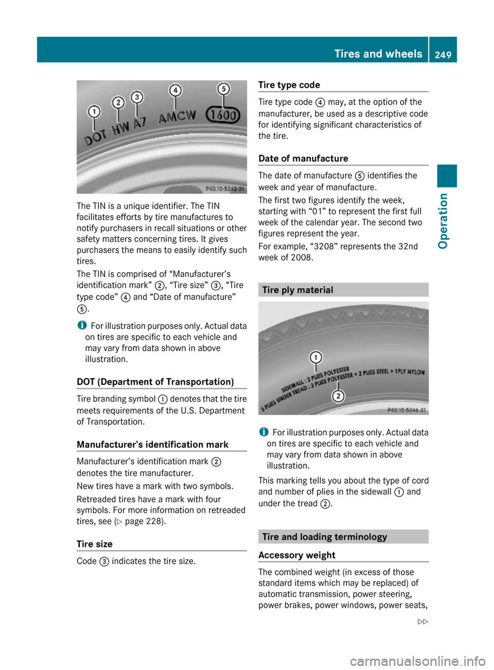
The TIN is a unique identifier. The TIN
facilitates efforts by tire manufactures to
notify purchasers in recall situations or other
safety matters concerning tires. It gives
purchasers the means to easily identify such
tires.
The TIN is comprised of “Manufacturer’s
identification mark” ;, “Tire size” =, “Tire
type code” ? and “Date of manufacture”
A.
iFor illustration purposes only. Actual data
on tires are specific to each vehicle and
may vary from data shown in above
illustration.
DOT (Department of Transportation)
Tire branding symbol : denotes that the tire
meets requirements of the U.S. Department
of Transportation.
Manufacturer’s identification mark
Manufacturer’s identification mark ;
denotes the tire manufacturer.
New tires have a mark with two symbols.
Retreaded tires have a mark with four
symbols. For more information on retreaded
tires, see (Y page 228).
Tire size
Code = indicates the tire size.
Tire type code
Tire type code ? may, at the option of the
manufacturer, be used as a descriptive code
for identifying significant characteristics of
the tire.
Date of manufacture
The date of manufacture A identifies the
week and year of manufacture.
The first two figures identify the week,
starting with “01” to represent the first full
week of the calendar year. The second two
figures represent the year.
For example, “3208” represents the 32nd
week of 2008.
Tire ply material
iFor illustration purposes only. Actual data
on tires are specific to each vehicle and
may vary from data shown in above
illustration.
This marking tells you about the type of cord
and number of plies in the sidewall : and
under the tread ;.
Tire and loading terminology
Accessory weight
The combined weight (in excess of those
standard items which may be replaced) of
automatic transmission, power steering,
power brakes, power windows, power seats,
Tires and wheels249Operation212_AKB; 2; 41, en-USd2ureepe,Version: 2.11.8.12009-07-17T09:14:21+02:00 - Seite 249Z