2010 MERCEDES-BENZ E63AMG Battery
[x] Cancel search: BatteryPage 164 of 372

Activating HOLD XMake sure the activation conditions are
met.
XDepress the brake pedal.XContinue to depress the brake pedal with
increased pedal pressure until the message
HOLD appears in the multifunction display.
The HOLD function is activated. You can
now release the brake pedal.
Example illustration, HOLD function activated
iIf the HOLD function is not activated when
depressing the brake pedal, wait briefly and
repeat the above steps.
GWarning!
The vehicle’s brakes are applied when the
HOLD function is activated. Therefore,
deactivate the HOLD function, for example,
when the vehicle is pulled through an
automatic car wash or being towed.
Deactivating HOLD
The HOLD function is switched off when
Ryou depress the accelerator pedal with the
automatic transmission in drive position D
or reverse gear R
Ryou shift the automatic transmission into
park position P
Ryou depress the brake pedal fully again
until the message HOLD in the multifunction
display disappears
Ryou activate the DISTRONIC PLUS
GWarning!
The braking effect of the HOLD function is
canceled and the vehicle can start to roll if
Rthe HOLD function is deactivated by
depressing the accelerator pedal or the
brake pedal
Rthe HOLD function or the power supply is
malfunctioning, e.g. due to battery failure
Rthe electrical components in the engine
compartment or the fuses have been
manipulated
Rthe battery is disconnected
GWarning!
Never get out of the vehicle while the HOLD
function is activated!
The HOLD function must never be operated
or deactivated by passengers or from outside
the vehicle.
The HOLD function does not replace the
parking brake. It must not be used to secure
the vehicle when parking.
Deactivate the HOLD function when leaving
or parking the vehicle. Use the parking brake
to secure the vehicle.
When the HOLD function is activated, the
automatic transmission shifts into park
position P automatically when
Ropening the driver’s door and releasing the
seat belt
Rturning off the engine
Ropening the hood
Ra system malfunction occurs
Rthe on-board voltage is insufficient
The HOLD function is deactivated.
AIRMATIC (E 550 and E 550 4MATIC)
Introduction
The AIRMATIC lets you select the chassis and
suspension setup. The chassis and
162Driving systemsControls in detail
212_AKB; 2; 41, en-USd2ureepe,Version: 2.11.8.12009-07-17T09:14:21+02:00 - Seite 162
Page 193 of 372
A quantity of outside air is added after
approximately 30 minutes.XDeactivating: Press button g again.
The indicator lamp above the button goes
out.
i The manually selected air recirculation
mode is deactivated automatically:
R after 5 minutes if the outside
temperature is below approximately
41‡ (5†)
R after 5 minutes if the air conditioning is
turned off
R after 30 minutes if the outside
temperature is above approximately
41‡ (5†)
Residual heat and ventilation
This feature is only available in Canada
vehicles with 3-zone automatic climate
control.
With the engine turned off, it is possible to
continue to heat or ventilate the interior for
up to 30 minutes. This feature makes use of
the residual heat produced by the engine.
i If you switch on the residual heat function
when outside temperatures are high, only
the ventilation will be switched on.
XActivating: Switch off the ignition.XPress button Ì.
The indicator lamp above the button comes
on.XDeactivating: Press button Ì.
The indicator lamp above the button goes
out.
The residual heat is deactivated
automatically:
R when the ignition is switched on
R after approximately 30 minutes
R if the battery voltage drops
ZONE function
The temperature can be adjusted for each
zone individually.
Dual-zone automatic climate controlXActivating: Press button á, rocker
switch E (Y page 181) or rocker switch
F (Y page 183).
The indicator lamp above button á
comes on.
The temperature can be adjusted for each
zone individually.XDeactivating: Press button á.
The indicator lamp above the button goes
out.
The temperature can be adjusted for all
zones via the driver’s-side settings.
3-zone automatic climate control
XActivating: Press button á.
The indicator lamp above the button comes
on.
The temperature can be adjusted for each
zone individually.XDeactivating: Press button á.
The indicator lamp above the button goes
out.
The temperature can be adjusted for all
zones via the driver’s-side settings.
Rear window defroster
GWarning!
Any accumulation of snow and ice should be
removed from the rear window before driving.
Visibility could otherwise be impaired,
endangering you and others.
The rear window defroster uses a large
amount of power. To keep the battery drain
to a minimum, switch off the defroster as
soon as the rear window is clear. The
defroster is switched off automatically after
Rear window defroster191Controls in detail212_AKB; 2; 41, en-USd2ureepe,Version: 2.11.8.12009-07-17T09:14:21+02:00 - Seite 191Z
Page 194 of 372

some time of operation depending on the
outside temperature.XSwitch on the ignition.XSwitching on: Press button ¤.
The indicator lamp above the button comes
on.XSwitching off: Press button ¤ again.
The rear window defroster switches off when
the battery voltage is too low. Too many
electrical consumers may be operating
simultaneously.
XSwitch off consumers that are currently not
needed if required.
Power tilt/sliding sunroof
Opening and closing
GObserve Safety notes, see page 56.GWarning!
When opening or closing the tilt/sliding
sunroof, make sure there is no danger of
anyone being harmed by the opening/closing
procedure.
The tilt/sliding sunroof is equipped with the
express operation and automatic reversal
function. If the movement of the tilt/sliding
sunroof is blocked during the closing
procedure, the tilt/sliding sunroof will stop
and open slightly.
The tilt/sliding sunroof operates differently
when the sunroof switch is pressed and held.
See the “Closing when the tilt/sliding sunroof
is blocked” section for details.
The opening/closing procedure of the tilt/
sliding sunroof can be immediately halted by
releasing the sunroof switch or, if the sunroof
switch was moved past the resistance point
and released, by moving the sunroof switch in
any direction.
GWarning!
The tilt/sliding sunroof is made out of glass.
In the event of an accident, the glass may
shatter. This may result in an opening in the
roof.
In a vehicle rollover, occupants not wearing
their seat belts or not wearing them properly
may be thrown out of the opening. Such an
opening also presents a potential for injury for
occupants wearing their seat belts properly as
entire body parts or portions of them may
protrude from the passenger compartment.
! To avoid damaging the seals, do not
transport any objects with sharp edges
which can stick out of the tilt/sliding
sunroof.
Do not open the tilt/sliding sunroof if there
is snow or ice on the roof, as this could
result in malfunctions.
If you cannot open or close the tilt/sliding
sunroof due to a malfunction contact
Roadside Assistance or an authorized
Mercedes-Benz Center.
! Please keep in mind that weather
conditions can sometimes change rapidly.
Make sure to close the tilt/sliding sunroof
when leaving the vehicle. If water enters
the vehicle interior, vehicle electronics
could be damaged which is not covered by
the Mercedes-Benz Limited Warranty.
i You can also open or close the tilt/sliding
sunroof using the SmartKey or the
KEYLESS-GO function, see “Summer
opening feature” ( Y page 107) and
“Convenience closing feature”
( Y page 108).
i After switching off the ignition or
removing the SmartKey from the starter
switch, you can operate the tilt/sliding
sunroof until you open the driver’s or front
passenger door. If no door was opened you
can operate the tilt/sliding sunroof for up
to 5 minutes.192Power tilt/sliding sunroofControls in detail
212_AKB; 2; 41, en-USd2ureepe,Version: 2.11.8.12009-07-17T09:14:21+02:00 - Seite 192
Page 208 of 372
Ashtrays
Center console ashtray
iA storage compartment is located under
the ashtray insert.
! The storage compartment is not heat-
proof. When smoking always make sure the
ashtray insert is present and properly
inserted.
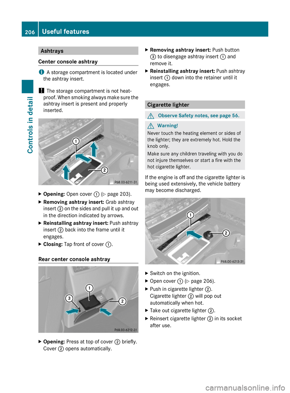
XOpening: Open cover : (Y page 203).XRemoving ashtray insert: Grab ashtray
insert ; on the sides and pull it up and out
in the direction indicated by arrows.
XReinstalling ashtray insert: Push ashtray
insert ; back into the frame until it
engages.
XClosing: Tap front of cover :.
Rear center console ashtray
XOpening: Press at top of cover ; briefly.
Cover ; opens automatically.
XRemoving ashtray insert: Push button
= to disengage ashtray insert : and
remove it.
XReinstalling ashtray insert: Push ashtray
insert : down into the retainer until it
engages.
Cigarette lighter
GObserve Safety notes, see page 56.GWarning!
Never touch the heating element or sides of
the lighter; they are extremely hot. Hold the
knob only.
Make sure any children traveling with you do
not injure themselves or start a fire with the
hot cigarette lighter.
If the engine is off and the cigarette lighter is
being used extensively, the vehicle battery
may become discharged.
XSwitch on the ignition.XOpen cover : (Y page 206).XPush in cigarette lighter ;.
Cigarette lighter ; will pop out
automatically when hot.
XTake out cigarette lighter ;.XReinsert cigarette lighter ; in its socket
after use.
206Useful featuresControls in detail
212_AKB; 2; 41, en-USd2ureepe,Version: 2.11.8.12009-07-17T09:14:21+02:00 - Seite 206
Page 209 of 372
Power outlets
The power outlets can be used to
accommodate 12V DC electrical accessories
(e.g. auxiliary lamps, mobile phone chargers)
up to a maximum of 15 A (180 W).
If the engine is off and the power outlets are
being used extensively, the vehicle battery
may become discharged.
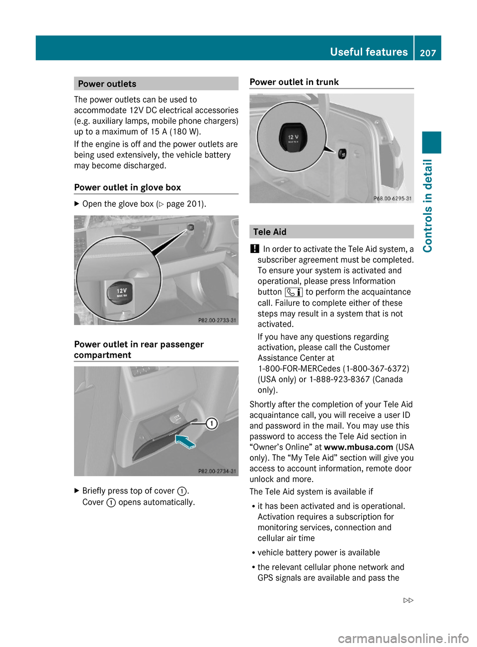
Power outlet in glove box
XOpen the glove box (Y page 201).
Power outlet in rear passenger
compartment
XBriefly press top of cover :.
Cover : opens automatically.
Power outlet in trunk
Tele Aid
! In order to activate the Tele Aid system, a
subscriber agreement must be completed.
To ensure your system is activated and
operational, please press Information
button ï to perform the acquaintance
call. Failure to complete either of these
steps may result in a system that is not
activated.
If you have any questions regarding
activation, please call the Customer
Assistance Center at
1-800-FOR-MERCedes (1-800-367-6372)
(USA only) or 1-888-923-8367 (Canada
only).
Shortly after the completion of your Tele Aid
acquaintance call, you will receive a user ID
and password in the mail. You may use this
password to access the Tele Aid section in
“Owner’s Online” at www.mbusa.com (USA
only). The “My Tele Aid” section will give you
access to account information, remote door
unlock and more.
The Tele Aid system is available if
Rit has been activated and is operational.
Activation requires a subscription for
monitoring services, connection and
cellular air time
Rvehicle battery power is available
Rthe relevant cellular phone network and
GPS signals are available and pass the
Useful features207Controls in detail212_AKB; 2; 41, en-USd2ureepe,Version: 2.11.8.12009-07-17T09:14:21+02:00 - Seite 207Z
Page 217 of 372
Reprogramming a single signal
transmitter button
To program a device using a signal
transmitter button previously trained, follow
these steps:
XSwitch on the ignition.XPress and hold the desired signal
transmitter button ( ;, = or ?). Do not
release the button.
Indicator lamp : will begin to flash after
20 seconds.XWithout releasing the signal transmitter
button, proceed with programming starting
with step 3.
Operation of integrated remote control
XSwitch on the ignition.XSelect and press the appropriate
integrated signal transmitter button ( ;,
= or ?) to activate the remote controlled
device.
The integrated remote control transmitter
continues to send the signal as long as the
button is pressed – up to 20 seconds.
Erasing the integrated remote control
memory
i If you sell your vehicle, erase the codes of
all three channels.
XSwitch on the ignition.XSimultaneously press and hold outer signal
transmitter buttons ; and ?, for
approximately 20 seconds, until indicator
lamp : flashes rapidly. Do not hold for
longer than 30 seconds.
The codes of all three channels are erased.Programming tips
If you are having difficulty programming the
integrated remote control, here are some
helpful tips:
R Check the frequency of hand-held remote
control A (typically located on the reverse
side of the remote). The integrated remote
control is compatible with radio-frequency
devices operating between 280-390 MHz.
R Put a new battery in hand-held remote
control A. This will increase the likelihood
of the hand-held remote control sending a
stronger and more accurate signal to the
integrated remote control.
R While performing step 3, hold hand-held
remote control A at different lengths and
angles from the signal transmitter button
( ; , = or ?) you are programming.
Attempt varying angles at the distance of 2
to 12 inches (5 to 30 cm) away or the same
angle at varying distances.
R If another hand-held remote control is
available for the same device, try the
programming steps again using that other
hand-held remote control. Make sure new
batteries are in the hand-held remote
control before beginning the procedure.
R Straighten the antenna wire from the
garage door opener assembly. This may
help improve transmitting and/or receiving
signals.
i Certain types of garage door openers are
incompatible with the integrated remote
control. If you should experience further
difficulties with programming the
integrated remote control, contact an
authorized Mercedes-Benz Center, or call
the Mercedes-Benz Customer Assistance
Center (USA only) at
1-800-FOR-MERCedes (1-800-367-6372),
or the HomeLink ®
Hotline (USA only) at
1-800-355-3515, or the Customer Service
(Canada only) at 1-800-387-0100.
Useful features215Controls in detail212_AKB; 2; 41, en-USd2ureepe,Version: 2.11.8.12009-07-17T09:14:21+02:00 - Seite 215Z
Page 253 of 372
Maximum permissible tire inflation
pressure
This number is the greatest amount of air
pressure that should ever be put in the tire.
Normal occupant weight
The number of occupants the vehicle is
designed to seat, multiplied by 68 kilograms
(150 lb).
Occupant distribution
The distribution of occupants in a vehicle at
their designated seating positions.
Production options weight
The combined weight of those installed
regular production options weighing over
5 lbs (2.3 kilograms) in excess of those
standard items which they replace, not
previously considered in curb weight or
accessory weight, including heavy duty
brakes, ride levelers, roof rack, heavy duty
battery, and special trim.
PSI (Pounds per square inch)
A standard unit of measure for air pressure.
Recommended tire inflation pressure
The recommended tire inflation pressure for
normal driving conditions is listed on the Tire
and Loading Information placard located on
the driver’s door B-pillar. It provides best
handling, tread life and riding comfort.
Supplemental information pertaining to
special driving situations can be found on the
tire inflation pressure label on the inside of
the fuel filler flap.
Rim
A metal support for a tire or a tire and tube
assembly upon which the tire beads are
seated.
Sidewall
The portion of a tire between the tread and
the bead.
TIN (Tire Identification Number)
Unique identifier which facilitates efforts by
tire manufacturers to notify purchasers in
recall situations or other safety matters
concerning tires and gives purchasers the
means to easily identify such tires. The TIN is
comprised of “Manufacturer’s identification
mark”, “Tire size”, “Tire type code” and “Date
of manufacture”.
Tire ply composition and material used
This indicates the number of plies or the
number of layers of rubber-coated fabric in
the tire tread and sidewall. Tire
manufacturers also must indicate the ply
materials in the tire and sidewall, which
include steel, nylon, polyester, and others.
Tire speed rating
Part of tire designation (speed symbol);
indicates the speed range for which a tire is
approved.
Total load limit
Rated cargo and luggage load plus
68 kilograms (150 lb) times the vehicle’s
designated seating capacity.
Traction
The adhesive friction of a tire on a surface on
which it moves. The amount of grip provided.
Tread
The portion of a tire that comes into contact
with the road.
Tires and wheels251Operation212_AKB; 2; 41, en-USd2ureepe,Version: 2.11.8.12009-07-17T09:14:21+02:00 - Seite 251Z
Page 261 of 372

Clearing the maintenance service
indicator message
The maintenance service indicator message
is cleared automatically
R after approximately 10 seconds when you
switch on the ignition
R after approximately 10 seconds when
reaching the service threshold while driving
R after approximately 30 seconds, once the
suggested maintenance service term has
passed
XClearing the maintenance service
indicator message manually: Press
button % or button a on the
multifunction steering wheel.
The standard display appears in the
multifunction display.
Maintenance service term exceeded
If you have exceeded the suggested
maintenance service term, you will see the
following message in the multifunction
display:
Service A Exceeded by XXXXX miles
(km)
Service A Exceeded by XXX days
In addition, a signal sounds when the
message appears.
Any authorized Mercedes-Benz Center will
reset the maintenance service indicator
following a completed maintenance service.
Calling up the maintenance service
indicator display
i The menu overview can be found on
( Y page 129).
You can call up the maintenance service
indicator display at any time to check when
the next maintenance service is required.
XSwitch on the ignition.
The standard display of the control system
appears ( Y page 129).XPress button = or ; on the
multifunction steering wheel to select the
Serv. menu.XPress button : or 9 to select
ASSYST PLUS .XPress button a on the multifunction
steering wheel to confirm.
The maintenance service indicator display
with the maintenance service deadline
appears in the multifunction display.
i If the battery was disconnected, the days
of disconnection will not be included in the
count shown by the maintenance service
indicator. To arrive at the true maintenance
service deadline, you will need to subtract
these days from the days shown in the
maintenance service indicator message or
maintenance service indicator display.
Resetting the maintenance service
indicator
In the event that the maintenance service on
your vehicle is not carried out at an authorized
Mercedes-Benz Center, you can have the
maintenance service indicator reset.
The automotive maintenance facility carrying
out the maintenance service will find the
information for resetting the maintenance
service indicator in the maintenance-relevant
literature for your vehicle.
Such literature is available at any authorized
Mercedes-Benz Center or directly from
Mercedes-Benz.
! If the maintenance service indicator was
reset inadvertently, have an authorized
Mercedes-Benz Center correct it.
Only reset the maintenance service
indicator if the proper maintenance service
has been performed. Not following the
proper maintenance service as described
in the Maintenance Booklet will result in
Maintenance259Operation212_AKB; 2; 41, en-USd2ureepe,Version: 2.11.8.12009-07-17T09:14:21+02:00 - Seite 259Z