2010 MERCEDES-BENZ E350 towing
[x] Cancel search: towingPage 243 of 372

Weight Rating (GVWR) and the Gross Axle
Weight Rating (GAWR) for either the front or
rear axle. You can obtain the GVWR and
GAWR from the certification label. The
certification label can be found on the driver’s
door B-pillar, see the “Technical data” section
(Y page 346).
Gross Vehicle Weight Rating (GVWR): The
total weight of the vehicle, all occupants, all
cargo, and the trailer tongue load (if
applicable) must never exceed the GVWR.
Gross Axle Weight Rating (GAWR): The total
allowable weight that can be carried by a
single axle (front or rear).
To assure that your vehicle does not exceed
the maximum permissible weight limits
(GVWR and GAWR for front and rear axle),
have the loaded vehicle (including driver,
passengers and all cargo and, if applicable,
trailer fully loaded) weighed on a suitable
commercial scale.
Trailer tongue load
The tongue load of any trailer is an important
weight to measure because it affects the load
you can carry in your vehicle. If a trailer is
towed, the tongue load must be added to the
weight of all occupants riding and any cargo
you are carrying in the vehicle. The tongue
load typically is 10% of the trailer weight and
everything loaded in it.
Your Mercedes-Benz has been designed
primarily to carry passengers and their cargo.
Mercedes-Benz does not recommend trailer
towing with your vehicle.
Maximum tire load
GWarning!
Do not overload the tires by exceeding the
specified load limit as indicated on the Tire
and Loading Information placard on the
driver’s door B-pillar. Overloading the tires
can overheat them, possibly causing a
blowout. Overloading the tires can also result
in handling or steering problems, or brake
failure.
iFor illustration purposes only. Actual data
on tires are specific to each vehicle and
may vary from data shown in above
illustration.
The maximum tire load rating : is the
maximum weight the tires are designed to
support.
For more information on tire load rating, see
(Y page 246).
For information on calculating total and cargo
load capacities, see (Y page 238).
Direction of rotation
Unidirectional tires offer added advantages,
such as better hydroplaning performance. To
benefit, however, you must make sure the
tires rotate in the direction specified.
An arrow on the sidewall indicates the
intended direction of rotation of the tire.
Spare wheels may be mounted against the
direction of rotation (spinning) even with a
unidirectional tire for temporary use only until
the regular drive wheel has been repaired or
replaced. Always observe and follow
applicable temporary use restrictions and
speed limitations indicated on the spare
wheel.
Tires and wheels241Operation212_AKB; 2; 41, en-USd2ureepe,Version: 2.11.8.12009-07-17T09:14:21+02:00 - Seite 241Z
Page 269 of 372

Vehicle equipment ............................268
Where will I find ...? ..........................268
Vehicle status messages in the
multifunction display .......................272
What to do if … ..................................304
Unlocking/locking manually ...........314
Resetting activated NECK-PRO
active front head restraints .............316
Replacing SmartKey batteries .........317
Replacing bulbs .................................318
Replacing wiper blades ....................322
Flat tire ..............................................323
Bleeding the fuel system (diesel
engine only) .......................................333
AdBlue® (diesel engine only) ...........333
Battery ...............................................336
Jump starting ....................................338
Towing the vehicle ............................340
Fuses ..................................................343
267Practical hints212_AKB; 2; 41, en-USd2ureepe,Version: 2.11.8.12009-07-17T09:14:21+02:00 - Seite 267
Page 270 of 372
Vehicle equipment
iThis Operator’s Manual describes all
features, standard or optional, potentially
available for your vehicle at the time of
purchase. Please be aware that your
vehicle might not be equipped with all
features described in this manual.
Where will I find ...?
First aid kit
iCheck expiration dates and contents for
completeness at least once a year and
replace missing/expired items.
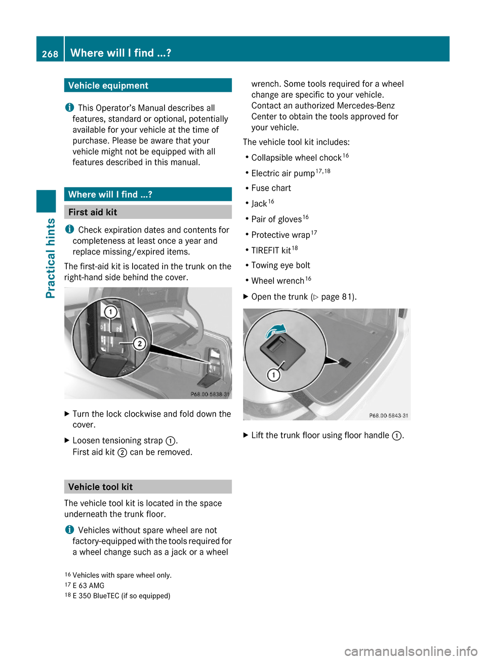
The first-aid kit is located in the trunk on the
right-hand side behind the cover.
XTurn the lock clockwise and fold down the
cover.
XLoosen tensioning strap :.
First aid kit ; can be removed.
Vehicle tool kit
The vehicle tool kit is located in the space
underneath the trunk floor.
iVehicles without spare wheel are not
factory-equipped with the tools required for
a wheel change such as a jack or a wheel
wrench. Some tools required for a wheel
change are specific to your vehicle.
Contact an authorized Mercedes-Benz
Center to obtain the tools approved for
your vehicle.
The vehicle tool kit includes:
RCollapsible wheel chock16
RElectric air pump17,18
RFuse chart
RJack16
RPair of gloves16
RProtective wrap17
RTIREFIT kit18
RTowing eye bolt
RWheel wrench16
XOpen the trunk (Y page 81).XLift the trunk floor using floor handle :.16Vehicles with spare wheel only.17E 63 AMG18E 350 BlueTEC (if so equipped)
268Where will I find ...?Practical hints
212_AKB; 2; 41, en-USd2ureepe,Version: 2.11.8.12009-07-17T09:14:21+02:00 - Seite 268
Page 271 of 372
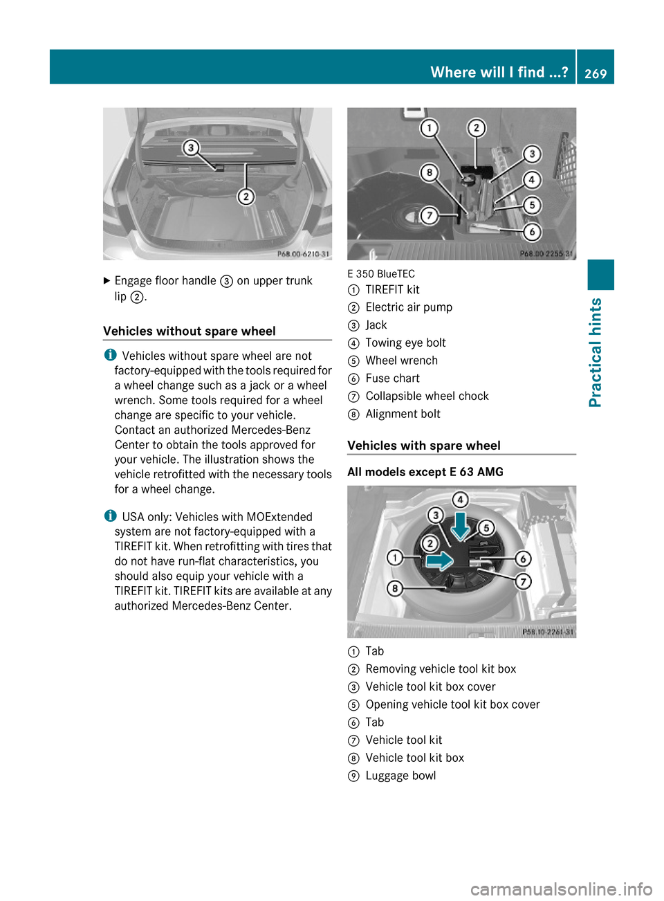
XEngage floor handle = on upper trunk
lip ;.
Vehicles without spare wheel
iVehicles without spare wheel are not
factory-equipped with the tools required for
a wheel change such as a jack or a wheel
wrench. Some tools required for a wheel
change are specific to your vehicle.
Contact an authorized Mercedes-Benz
Center to obtain the tools approved for
your vehicle. The illustration shows the
vehicle retrofitted with the necessary tools
for a wheel change.
iUSA only: Vehicles with MOExtended
system are not factory-equipped with a
TIREFIT kit. When retrofitting with tires that
do not have run-flat characteristics, you
should also equip your vehicle with a
TIREFIT kit. TIREFIT kits are available at any
authorized Mercedes-Benz Center.
E 350 BlueTEC
:TIREFIT kit;Electric air pump=Jack?Towing eye boltAWheel wrenchBFuse chartCCollapsible wheel chockDAlignment bolt
Vehicles with spare wheel
All models except E 63 AMG
:Tab;Removing vehicle tool kit box=Vehicle tool kit box coverAOpening vehicle tool kit box coverBTabCVehicle tool kitDVehicle tool kit boxELuggage bowlWhere will I find ...?269Practical hints212_AKB; 2; 41, en-USd2ureepe,Version: 2.11.8.12009-07-17T09:14:21+02:00 - Seite 269Z
Page 272 of 372
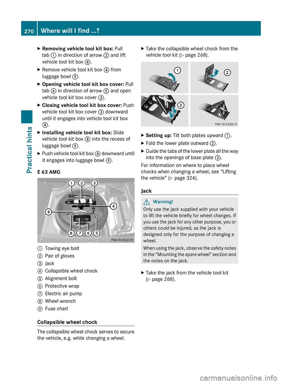
XRemoving vehicle tool kit box: Pull
tab : in direction of arrow ; and lift
vehicle tool kit box D.
XRemove vehicle tool kit box D from
luggage bowl E.
XOpening vehicle tool kit box cover: Pull
tab B in direction of arrow A and open
vehicle tool kit box cover =.
XClosing vehicle tool kit box cover: Push
vehicle tool kit box cover = downward
until it engages into vehicle tool kit box
D.
XInstalling vehicle tool kit box: Slide
vehicle tool kit box D into the recess of
luggage bowl E.
XPush vehicle tool kit box D downward until
it engages into luggage bowl E.
E 63 AMG
:Towing eye bolt;Pair of gloves=Jack?Collapsible wheel chockAAlignment boltBProtective wrapCElectric air pumpDWheel wrenchEFuse chart
Collapsible wheel chock
The collapsible wheel chock serves to secure
the vehicle, e.g. while changing a wheel.
XTake the collapsible wheel chock from the
vehicle tool kit (Y page 268).
XSetting up: Tilt both plates upward :.XFold the lower plate outward ;.XGuide the tabs of the lower plate all the way
into the openings of base plate =.
For information on where to place wheel
chocks when changing a wheel, see “Lifting
the vehicle” (Y page 324).
Jack
GWarning!
Only use the jack supplied with your vehicle
to lift the vehicle briefly for wheel changes. If
you use the jack for any other purpose, you or
others could be injured, as the jack is
designed only for the purpose of changing a
wheel.
When using the jack, observe the safety notes
in the “Mounting the spare wheel” section and
the notes on the jack.
XTake the jack from the vehicle tool kit
(Y page 268).
270Where will I find ...?Practical hints
212_AKB; 2; 41, en-USd2ureepe,Version: 2.11.8.12009-07-17T09:14:21+02:00 - Seite 270
Page 342 of 372
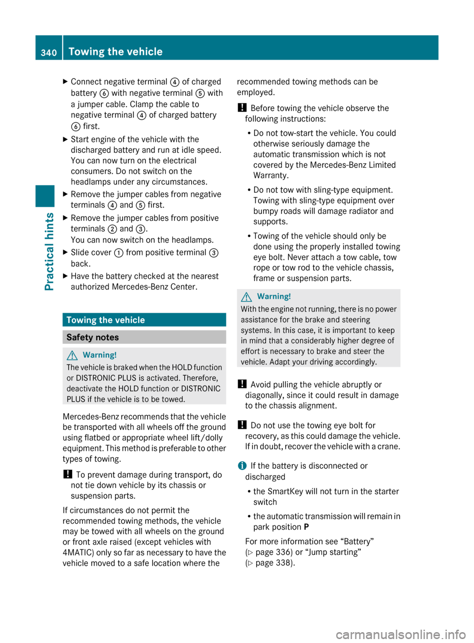
XConnect negative terminal ? of charged
battery B with negative terminal A with
a jumper cable. Clamp the cable to
negative terminal ? of charged battery
B first.XStart engine of the vehicle with the
discharged battery and run at idle speed.
You can now turn on the electrical
consumers. Do not switch on the
headlamps under any circumstances.XRemove the jumper cables from negative
terminals ? and A first.XRemove the jumper cables from positive
terminals ; and =.
You can now switch on the headlamps.XSlide cover : from positive terminal =
back.XHave the battery checked at the nearest
authorized Mercedes-Benz Center.
Towing the vehicle
Safety notes
GWarning!
The vehicle is braked when the HOLD function
or DISTRONIC PLUS is activated. Therefore,
deactivate the HOLD function or DISTRONIC
PLUS if the vehicle is to be towed.
Mercedes-Benz recommends that the vehicle
be transported with all wheels off the ground
using flatbed or appropriate wheel lift/dolly
equipment. This method is preferable to other
types of towing.
! To prevent damage during transport, do
not tie down vehicle by its chassis or
suspension parts.
If circumstances do not permit the
recommended towing methods, the vehicle
may be towed with all wheels on the ground
or front axle raised (except vehicles with
4MATIC) only so far as necessary to have the
vehicle moved to a safe location where the
recommended towing methods can be
employed.
! Before towing the vehicle observe the
following instructions:
R Do not tow-start the vehicle. You could
otherwise seriously damage the
automatic transmission which is not
covered by the Mercedes-Benz Limited
Warranty.
R Do not tow with sling-type equipment.
Towing with sling-type equipment over
bumpy roads will damage radiator and
supports.
R Towing of the vehicle should only be
done using the properly installed towing
eye bolt. Never attach a tow cable, tow
rope or tow rod to the vehicle chassis,
frame or suspension parts.GWarning!
With the engine not running, there is no power
assistance for the brake and steering
systems. In this case, it is important to keep
in mind that a considerably higher degree of
effort is necessary to brake and steer the
vehicle. Adapt your driving accordingly.
! Avoid pulling the vehicle abruptly or
diagonally, since it could result in damage
to the chassis alignment.
! Do not use the towing eye bolt for
recovery, as this could damage the vehicle.
If in doubt, recover the vehicle with a crane.
i If the battery is disconnected or
discharged
R the SmartKey will not turn in the starter
switch
R the automatic transmission will remain in
park position P
For more information see “Battery”
( Y page 336) or “Jump starting”
( Y page 338).
340Towing the vehiclePractical hints
212_AKB; 2; 41, en-USd2ureepe,Version: 2.11.8.12009-07-17T09:14:21+02:00 - Seite 340
Page 343 of 372
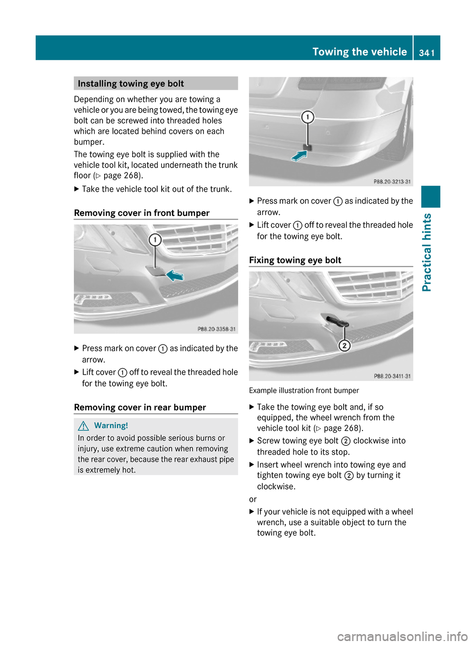
Installing towing eye bolt
Depending on whether you are towing a
vehicle or you are being towed, the towing eye
bolt can be screwed into threaded holes
which are located behind covers on each
bumper.
The towing eye bolt is supplied with the
vehicle tool kit, located underneath the trunk
floor (Y page 268).
XTake the vehicle tool kit out of the trunk.
Removing cover in front bumper
XPress mark on cover : as indicated by the
arrow.
XLift cover : off to reveal the threaded hole
for the towing eye bolt.
Removing cover in rear bumper
GWarning!
In order to avoid possible serious burns or
injury, use extreme caution when removing
the rear cover, because the rear exhaust pipe
is extremely hot.
XPress mark on cover : as indicated by the
arrow.
XLift cover : off to reveal the threaded hole
for the towing eye bolt.
Fixing towing eye bolt
Example illustration front bumper
XTake the towing eye bolt and, if so
equipped, the wheel wrench from the
vehicle tool kit (Y page 268).
XScrew towing eye bolt ; clockwise into
threaded hole to its stop.
XInsert wheel wrench into towing eye and
tighten towing eye bolt ; by turning it
clockwise.
or
XIf your vehicle is not equipped with a wheel
wrench, use a suitable object to turn the
towing eye bolt.
Towing the vehicle341Practical hints212_AKB; 2; 41, en-USd2ureepe,Version: 2.11.8.12009-07-17T09:14:21+02:00 - Seite 341Z
Page 344 of 372
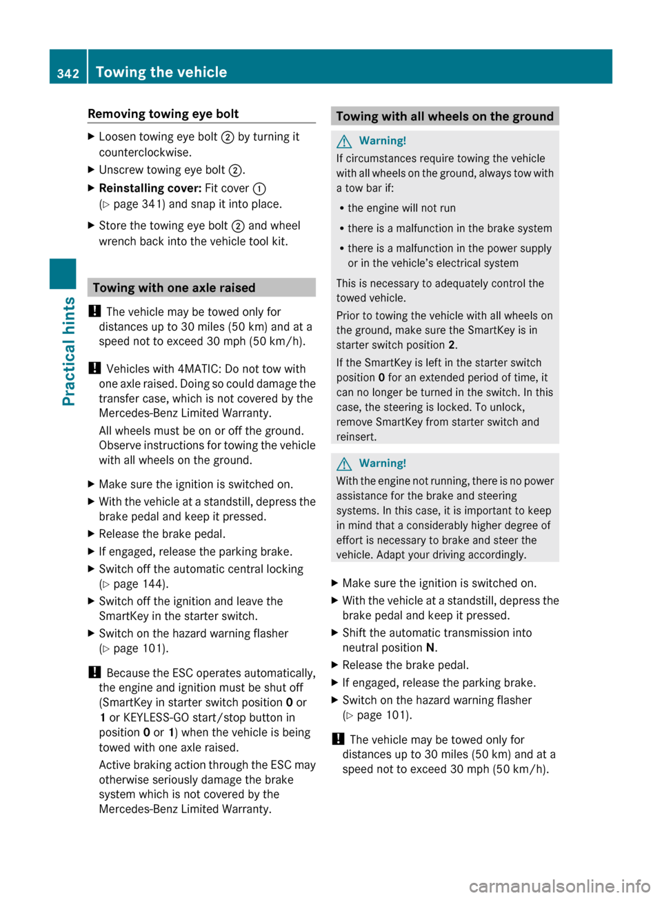
Removing towing eye boltXLoosen towing eye bolt ; by turning it
counterclockwise.XUnscrew towing eye bolt ;.XReinstalling cover: Fit cover :
( Y page 341) and snap it into place.XStore the towing eye bolt ; and wheel
wrench back into the vehicle tool kit.
Towing with one axle raised
! The vehicle may be towed only for
distances up to 30 miles (50 km) and at a
speed not to exceed 30 mph (50 km/h).
! Vehicles with 4MATIC: Do not tow with
one axle raised. Doing so could damage the
transfer case, which is not covered by the
Mercedes-Benz Limited Warranty.
All wheels must be on or off the ground.
Observe instructions for towing the vehicle
with all wheels on the ground.
XMake sure the ignition is switched on.XWith the vehicle at a standstill, depress the
brake pedal and keep it pressed.XRelease the brake pedal.XIf engaged, release the parking brake.XSwitch off the automatic central locking
( Y page 144).XSwitch off the ignition and leave the
SmartKey in the starter switch.XSwitch on the hazard warning flasher
( Y page 101).
!
Because the ESC operates automatically,
the engine and ignition must be shut off
(SmartKey in starter switch position 0 or
1 or KEYLESS-GO start/stop button in
position 0 or 1) when the vehicle is being
towed with one axle raised.
Active braking action through the ESC may
otherwise seriously damage the brake
system which is not covered by the
Mercedes-Benz Limited Warranty.
Towing with all wheels on the groundGWarning!
If circumstances require towing the vehicle
with all wheels on the ground, always tow with
a tow bar if:
R the engine will not run
R there is a malfunction in the brake system
R there is a malfunction in the power supply
or in the vehicle’s electrical system
This is necessary to adequately control the
towed vehicle.
Prior to towing the vehicle with all wheels on
the ground, make sure the SmartKey is in
starter switch position 2.
If the SmartKey is left in the starter switch
position 0 for an extended period of time, it
can no longer be turned in the switch. In this
case, the steering is locked. To unlock,
remove SmartKey from starter switch and
reinsert.
GWarning!
With the engine not running, there is no power
assistance for the brake and steering
systems. In this case, it is important to keep
in mind that a considerably higher degree of
effort is necessary to brake and steer the
vehicle. Adapt your driving accordingly.
XMake sure the ignition is switched on.XWith the vehicle at a standstill, depress the
brake pedal and keep it pressed.XShift the automatic transmission into
neutral position N.XRelease the brake pedal.XIf engaged, release the parking brake.XSwitch on the hazard warning flasher
( Y page 101).
!
The vehicle may be towed only for
distances up to 30 miles (50 km) and at a
speed not to exceed 30 mph (50 km/h).
342Towing the vehiclePractical hints
212_AKB; 2; 41, en-USd2ureepe,Version: 2.11.8.12009-07-17T09:14:21+02:00 - Seite 342