2010 MERCEDES-BENZ E350 clock
[x] Cancel search: clockPage 273 of 372
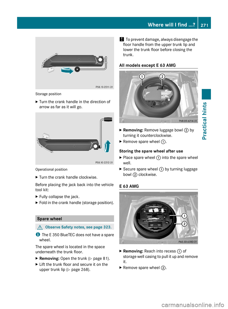
Storage position
XTurn the crank handle in the direction of
arrow as far as it will go.
Operational position
XTurn the crank handle clockwise.
Before placing the jack back into the vehicle
tool kit:
XFully collapse the jack.XFold in the crank handle (storage position).
Spare wheel
GObserve Safety notes, see page 323.
iThe E 350 BlueTEC does not have a spare
wheel.
The spare wheel is located in the space
underneath the trunk floor.
XRemoving: Open the trunk (Y page 81).XLift the trunk floor and secure it on the
upper trunk lip (Y page 268).
! To prevent damage, always disengage the
floor handle from the upper trunk lip and
lower the trunk floor before closing the
trunk.
All models except E 63 AMG
XRemoving: Remove luggage bowl ; by
turning it counterclockwise.
XRemove spare wheel :.
Storing the spare wheel after use
XPlace spare wheel : into the spare wheel
well.
XSecure spare wheel : by turning luggage
bowl ; clockwise.
E 63 AMG
XRemoving: Reach into recess : of
storage well casing to pull it up and remove
it.
XRemove spare wheel ;.Where will I find ...?271Practical hints212_AKB; 2; 41, en-USd2ureepe,Version: 2.11.8.12009-07-17T09:14:21+02:00 - Seite 271Z
Page 317 of 372

The anti-theft alarm system will trigger when
you
Runlock the driver’s door or the trunk with
the mechanical key
and
Ropen the driver’s door or the trunk
To cancel the alarm, insert the SmartKey into
the starter switch.
Removing the mechanical key
XMove locking tab : in the direction of
arrow.
XSlide mechanical key ; out of the housing.
Unlocking the driver’s door
XInsert mechanical key ; into the driver’s
door lock.
XTurn mechanical key ; counterclockwise
to position 1.
XPull the door handle to open the driver’s
door.
XTurn mechanical key ; back and remove
it from the driver’s door lock.
Unlocking the trunk
A minimum height clearance of 5.78 ft
(1.76 m) is required to open the trunk lid.
XInsert mechanical key ; into the trunk lid
lock.
XTurn mechanical key ; counterclockwise
to position 1.
! When you open the trunk, the trunk lid
swings open upwards. Always make sure
there is sufficient overhead clearance.
XTurn mechanical key ; back and remove
it from the trunk lid lock.
Locking the vehicle
If you cannot lock the vehicle with the
SmartKey or with KEYLESS-GO, lock it as
follows:
XOpen the driver’s door.XClose the front passenger door, the rear
doors, and the trunk.
XPress the central locking switch
(Y page 81).
The locking knobs of the front passenger
door and the rear doors move down.
XIf the vehicle battery is disconnected or
drained: Press down the locking knobs on
Unlocking/locking manually315Practical hints212_AKB; 2; 41, en-USd2ureepe,Version: 2.11.8.12009-07-17T09:14:21+02:00 - Seite 315Z
Page 318 of 372

the front passenger door and the rear
doors.
XExit the vehicle.XClose the driver’s door.XRemove mechanical key ; from the
SmartKey (Y page 315).
XInsert mechanical key ; into the driver’s
door lock.
XTurn mechanical key ; clockwise to
position 1.
The vehicle is locked.
XTurn mechanical key ; back and remove
it from the driver’s door lock.
XCheck whether the doors and the trunk are
locked.
XIf necessary, lock the trunk with the
mechanical key (Y page 85).
iThis procedure does not arm the anti-
theft alarm system, nor does it lock the fuel
filler flap.
Fuel filler flap
GWarning!
Avoid contact with the vehicle walls as they
may contain sharp edges. Otherwise, you
could injure yourself while releasing the fuel
filler flap.
In case the central locking system does not
release the fuel filler flap, you can open it
manually.
The fuel filler flap release is located on the
passenger side in the trunk behind the cover.
XOpen the trunk (Y page 81).XPush the parcel net down.XOpen the cover (Y page 268).XRemove fuel filler flap release ; from
holder :.
XPull fuel filler flap release ; in direction of
the arrow.
XOpen the fuel filler flap (Y page 220).XClose the cover.XClose the trunk.
Resetting activated NECK-PRO active
front head restraints
If the NECK-PRO active front head restraints
have been triggered in a rear-end collision,
they must be reset.
You can tell that the NECK-PRO active front
head restraints have been triggered when
they have been moved forward and cannot be
adjusted.
GWarning!
For safety reasons, have the NECK-PRO active
front head restraints checked at an
authorized Mercedes-Benz Center after a
rear-end collision.
316Resetting activated NECK-PRO active front head restraintsPractical hints
212_AKB; 2; 41, en-USd2ureepe,Version: 2.11.8.12009-07-17T09:14:21+02:00 - Seite 316
Page 322 of 372
recommended to have such work done by a
qualified technician.
Before you start to replace a bulb for a front
lamp, do the following:
XSwitch off the ignition.XTurn the exterior lamp switch to position
$.
XOpen the hood (Y page 223).
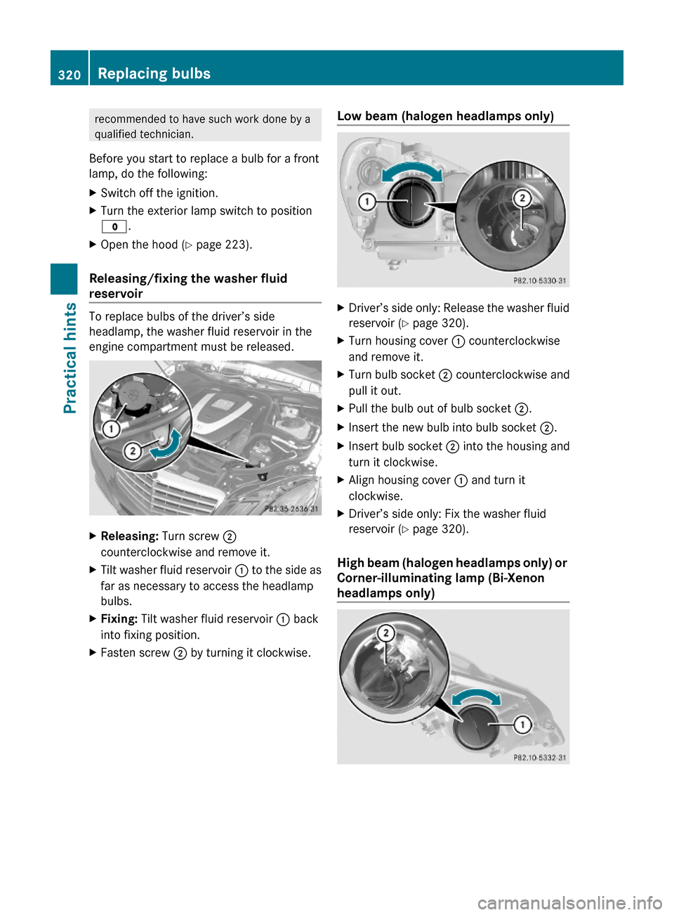
Releasing/fixing the washer fluid
reservoir
To replace bulbs of the driver’s side
headlamp, the washer fluid reservoir in the
engine compartment must be released.
XReleasing: Turn screw ;
counterclockwise and remove it.
XTilt washer fluid reservoir : to the side as
far as necessary to access the headlamp
bulbs.
XFixing: Tilt washer fluid reservoir : back
into fixing position.
XFasten screw ; by turning it clockwise.Low beam (halogen headlamps only)XDriver’s side only: Release the washer fluid
reservoir (Y page 320).
XTurn housing cover : counterclockwise
and remove it.
XTurn bulb socket ; counterclockwise and
pull it out.
XPull the bulb out of bulb socket ;.XInsert the new bulb into bulb socket ;.XInsert bulb socket ; into the housing and
turn it clockwise.
XAlign housing cover : and turn it
clockwise.
XDriver’s side only: Fix the washer fluid
reservoir (Y page 320).
High beam (halogen headlamps only) or
Corner-illuminating lamp (Bi-Xenon
headlamps only)
320Replacing bulbsPractical hints
212_AKB; 2; 41, en-USd2ureepe,Version: 2.11.8.12009-07-17T09:14:21+02:00 - Seite 320
Page 323 of 372
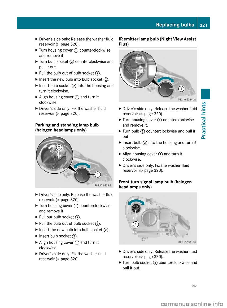
XDriver’s side only: Release the washer fluid
reservoir (Y page 320).
XTurn housing cover : counterclockwise
and remove it.
XTurn bulb socket ; counterclockwise and
pull it out.
XPull the bulb out of bulb socket ;.XInsert the new bulb into bulb socket ;.XInsert bulb socket ; into the housing and
turn it clockwise.
XAlign housing cover : and turn it
clockwise.
XDriver’s side only: Fix the washer fluid
reservoir (Y page 320).
Parking and standing lamp bulb
(halogen headlamps only)
XDriver’s side only: Release the washer fluid
reservoir (Y page 320).
XTurn housing cover : counterclockwise
and remove it.
XPull out bulb socket ;.XPull the bulb out of bulb socket ;.XInsert the new bulb into bulb socket ;.XInsert bulb socket ;.XAlign housing cover : and turn it
clockwise.
XDriver’s side only: Fix the washer fluid
reservoir (Y page 320).
IR emitter lamp bulb (Night View Assist
Plus)
XDriver’s side only: Release the washer fluid
reservoir (Y page 320).
XTurn housing cover : counterclockwise
and remove it.
XTurn bulb ; counterclockwise and pull it
out.
XInsert bulb ; into the housing and turn it
clockwise.
XAlign housing cover : and turn it
clockwise.
XDriver’s side only: Fix the washer fluid
reservoir (Y page 320).
Front turn signal lamp bulb (halogen
headlamps only)
XDriver’s side only: Release the washer fluid
reservoir (Y page 320).
XTurn bulb socket : counterclockwise and
pull it out.
Replacing bulbs321Practical hints212_AKB; 2; 41, en-USd2ureepe,Version: 2.11.8.12009-07-17T09:14:21+02:00 - Seite 321Z
Page 324 of 372
XTurn the bulb counterclockwise with light
pressure and pull it out of bulb socket :.
XInsert the new bulb into bulb socket : and
turn the bulb clockwise.
XInsert bulb socket : into the housing and
turn it clockwise.
XDriver’s side only: Fix the washer fluid
reservoir (Y page 320).
Replacing wiper blades
Safety notes
GWarning!
For safety reasons, switch off the wipers and
remove the SmartKey from the starter switch
(vehicles with KEYLESS-GO: Make sure the
vehicle’s on-board electronics have status 0)
before replacing a wiper blade. Otherwise, the
wiper motor could suddenly turn on and cause
injury.
GWarning!
Wiper blades are components that are subject
to wear and tear. Replace the wiper blades
twice a year, preferably in the spring and fall.
Otherwise the windshield will not be wiped
properly. As a result, you may not be able to
observe surrounding traffic conditions and
could cause an accident.
! Never open the hood when a wiper arm is
folded forward.
Hold on to the wiper when folding a wiper
arm back. If released, the force of the
impact from the tensioning spring could
crack the windshield.
Do not allow a wiper arm to contact the
windshield glass without a wiper blade
inserted.
Mercedes-Benz recommends that you have
this work carried out at an authorized
Mercedes-Benz Center.
XRemove the SmartKey from the starter
switch.
Vehicles with KEYLESS-GO:XMake sure the vehicle’s on-board
electronics have status 0 (Y page 86).
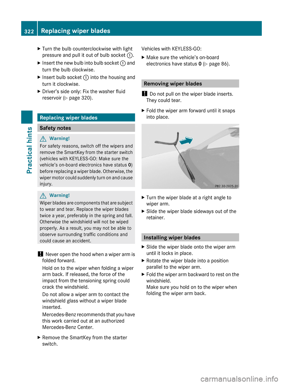
Removing wiper blades
! Do not pull on the wiper blade inserts.
They could tear.
XFold the wiper arm forward until it snaps
into place.
XTurn the wiper blade at a right angle to
wiper arm.
XSlide the wiper blade sideways out of the
retainer.
Installing wiper blades
XSlide the wiper blade onto the wiper arm
until it locks in place.
XRotate the wiper blade into a position
parallel to the wiper arm.
XFold the wiper arm backward to rest on the
windshield.
Make sure you hold on to the wiper when
folding the wiper arm back.
322Replacing wiper bladesPractical hints
212_AKB; 2; 41, en-USd2ureepe,Version: 2.11.8.12009-07-17T09:14:21+02:00 - Seite 322
Page 327 of 372
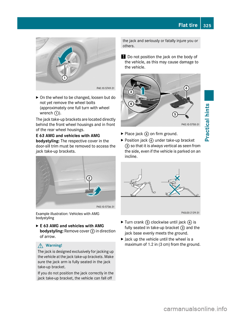
XOn the wheel to be changed, loosen but do
not yet remove the wheel bolts
(approximately one full turn with wheel
wrench :).
The jack take-up brackets are located directly
behind the front wheel housings and in front
of the rear wheel housings.
E 63 AMG and vehicles with AMG
bodystyling: The respective cover in the
door-sill trim must be removed to access the
jack take-up brackets.
Example illustration: Vehicles with AMGbodystyling
XE 63 AMG and vehicles with AMG
bodystyling: Remove cover ; in direction
of arrow.
GWarning!
The jack is designed exclusively for jacking up
the vehicle at the jack take-up brackets. Make
sure the jack arm is fully seated in the jack
take-up bracket.
If you do not position the jack correctly in the
jack take-up bracket, the vehicle can fall off
the jack and seriously or fatally injure you or
others.
! Do not position the jack on the body of
the vehicle, as this may cause damage to
the vehicle.
XPlace jack ? on firm ground.XPosition jack ? under take-up bracket
= so that it is always vertical as seen from
the side, even if the vehicle is parked on an
incline.
XTurn crank A clockwise until jack ? is
fully seated in take-up bracket = and the
jack base evenly meets the ground.
XJack up the vehicle until the wheel is a
maximum of 1.2 in (3 cm) from the ground.
Flat tire325Practical hints212_AKB; 2; 41, en-USd2ureepe,Version: 2.11.8.12009-07-17T09:14:21+02:00 - Seite 325Z
Page 330 of 372
XTurn the SmartKey in the starter switch to
position 1.
or
XVehicles with KEYLESS-GO: Press the
KEYLESS-GO start/stop button once. Do
not depress the brake pedal.
XPress I on electric air pump switch ;.
The electric air pump switches on and
inflates the collapsible tire.
XInflate the collapsible tire to the
recommended tire inflation pressure as
specified for your vehicle (Y page 358).
This should take approximately 5 minutes.
GWarning!
The air hose and the union nut can become
hot during inflation. Exercise proper caution
to avoid burning yourself when using the
equipment.
! Do not operate the electric air pump
longer than 8 minutes without interruption.
Otherwise it may overheat.
You may operate the air pump again after
it has cooled off.
! Compare the recommended tire inflation
pressure for your vehicle with the tire
inflation pressure on the yellow label
located on the spare wheel rim.
If the tire inflation pressure on the yellow
label on the spare wheel rim differs from
the values given in this Operator’s Manual,
inflate the tire to the recommended tire
inflation pressure given on the yellow label
on the spare wheel rim.
XPress 0 on electric air pump switch ;.XTurn the SmartKey in the starter switch to
position 0.
or
XVehicles with KEYLESS-GO: Press the
KEYLESS-GO start/stop button twice. Do
not depress the brake pedal.
XVersion 1 only: If the tire inflation pressure
is above the recommended tire inflation
pressure as specified for your vehicle
(Y page 358), decrease tire pressure using
the vent screw on air hose ?.
XVersion 2 only: If the tire inflation pressure
is above the recommended tire inflation
pressure as specified for your vehicle
(Y page 358), decrease tire pressure using
deflate button B.
GObserve Safety notes, see page 231.XDetach the electric air pump.XReinstall collapsible tire valve cap.XVersion 1 only: Store electrical plug =
and air hose ? behind flap :.
XVersion 2 only: Store electrical plug =
and the air hose back into the pump
housing bottom.
XPlace the electric air pump back in its
designated storage space.
XLower the vehicle.
Lowering the vehicle
XLower the vehicle by turning the crank
counterclockwise until the vehicle is
resting fully on its own weight.
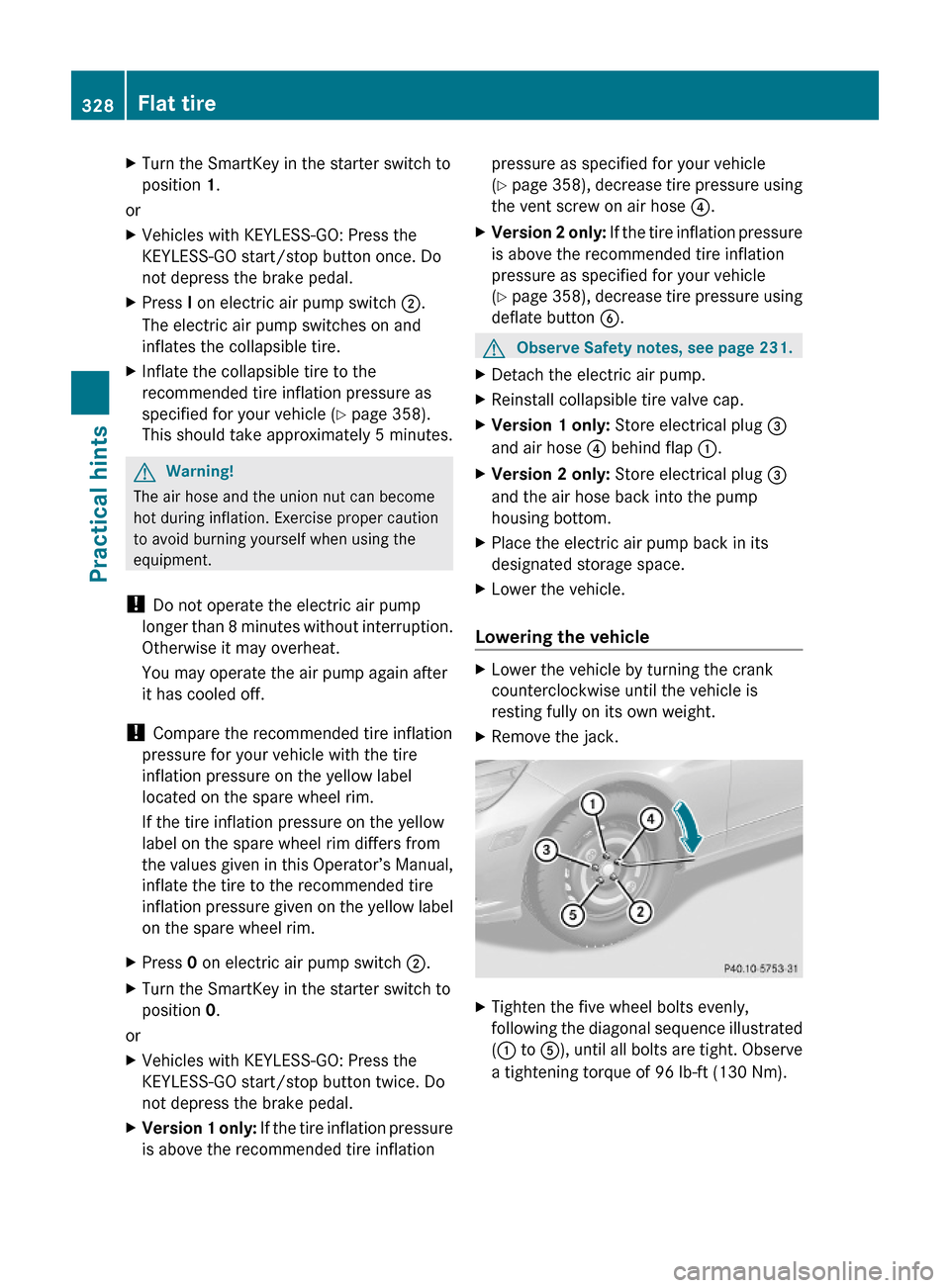
XRemove the jack.XTighten the five wheel bolts evenly,
following the diagonal sequence illustrated
(: to A), until all bolts are tight. Observe
a tightening torque of 96 lb-ft (130 Nm).
328Flat tirePractical hints
212_AKB; 2; 41, en-USd2ureepe,Version: 2.11.8.12009-07-17T09:14:21+02:00 - Seite 328