2010 MERCEDES-BENZ E350 Front
[x] Cancel search: FrontPage 323 of 372
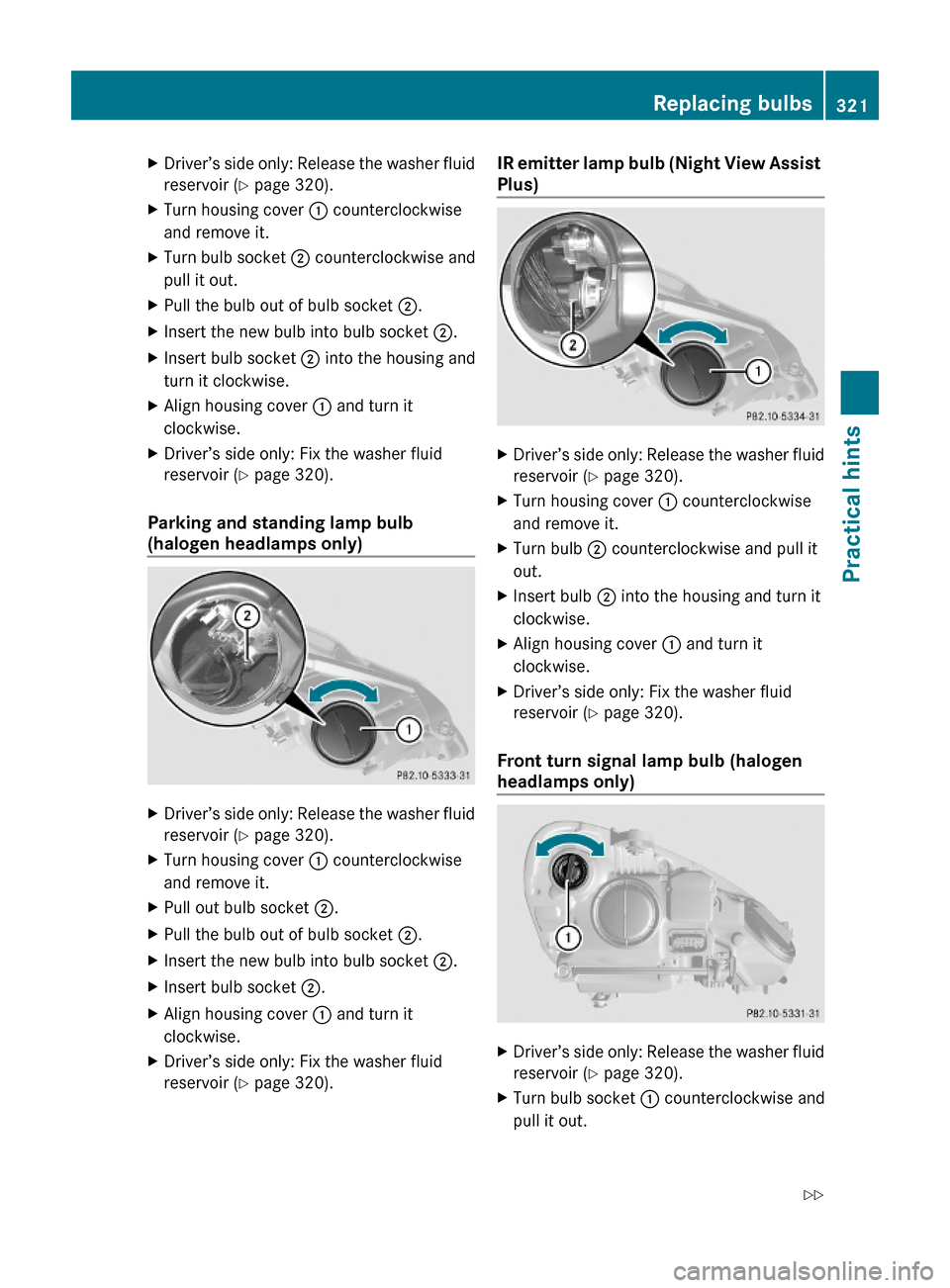
XDriver’s side only: Release the washer fluid
reservoir (Y page 320).
XTurn housing cover : counterclockwise
and remove it.
XTurn bulb socket ; counterclockwise and
pull it out.
XPull the bulb out of bulb socket ;.XInsert the new bulb into bulb socket ;.XInsert bulb socket ; into the housing and
turn it clockwise.
XAlign housing cover : and turn it
clockwise.
XDriver’s side only: Fix the washer fluid
reservoir (Y page 320).
Parking and standing lamp bulb
(halogen headlamps only)
XDriver’s side only: Release the washer fluid
reservoir (Y page 320).
XTurn housing cover : counterclockwise
and remove it.
XPull out bulb socket ;.XPull the bulb out of bulb socket ;.XInsert the new bulb into bulb socket ;.XInsert bulb socket ;.XAlign housing cover : and turn it
clockwise.
XDriver’s side only: Fix the washer fluid
reservoir (Y page 320).
IR emitter lamp bulb (Night View Assist
Plus)
XDriver’s side only: Release the washer fluid
reservoir (Y page 320).
XTurn housing cover : counterclockwise
and remove it.
XTurn bulb ; counterclockwise and pull it
out.
XInsert bulb ; into the housing and turn it
clockwise.
XAlign housing cover : and turn it
clockwise.
XDriver’s side only: Fix the washer fluid
reservoir (Y page 320).
Front turn signal lamp bulb (halogen
headlamps only)
XDriver’s side only: Release the washer fluid
reservoir (Y page 320).
XTurn bulb socket : counterclockwise and
pull it out.
Replacing bulbs321Practical hints212_AKB; 2; 41, en-USd2ureepe,Version: 2.11.8.12009-07-17T09:14:21+02:00 - Seite 321Z
Page 325 of 372
Flat tire
Safety notes
Your vehicle may be equipped with:
R a Minispare wheel
R a spare wheel with collapsible tire
R an MOExtended system (your vehicle does
not have a spare wheel or a TIREFIT kit)
R a TIREFIT kit 19
(your vehicle does not have
a spare wheel)
GWarning!
The dimensions of the spare wheel are
different from those of the road wheels. As a
result, the vehicle handling characteristics
change when driving with a spare wheel
mounted. Adapt your driving style
accordingly.
The spare wheel is for temporary use only.
When driving with a spare wheel mounted,
ensure proper tire inflation pressure and do
not exceed a vehicle speed of 50 mph
(80 km/h).
Contact the nearest authorized Mercedes-
Benz Center as soon as possible to have the
spare wheel replaced with a regular road
wheel.
Never operate the vehicle with more than one
spare wheel mounted.
Do not switch off the ESC when a spare wheel
is mounted.
Preparing the vehicle
XVehicles with AIRMATIC:
Make sure the vehicle level is set to normal
level ( Y page 163).XWhenever possible, park the vehicle in a
safe distance from moving traffic on a hard,
flat surface.XTurn on the hazard warning flasher.XTurn the steering wheel so that the front
wheels are in a straight-ahead position.XEngage the parking brake.XShift the automatic transmission into park
position P.XTurn off the engine.XRemove the SmartKey from the starter
switch.
or
XVehicles with KEYLESS-GO: Open the
driver’s door (this puts the starter switch in
position 0, same as with the SmartKey
removed from the starter switch). The
driver’s door can then be closed again.
Open doors only when conditions are safe
to do so.XVehicles with KEYLESS-GO: Remove the
KEYLESS-GO start/stop button from the
starter switch.XHave any passenger exit the vehicle at a
safe distance from the roadway. Open
doors only when conditions are safe to do
so.
Mounting the spare wheel
Introduction
XPrepare the vehicle as described
( Y page 323).XTake the following out of the vehicle:
R spare wheel
R jack
R vehicle tool kit
R collapsible wheel chock
R electric air pump (required for vehicles
with spare wheel with collapsible tire
only)
For information on where to find the
respective items, see “Where will I find ...?”
( Y page 268) and ( Y page 271).
19
Canada only.Flat tire323Practical hints212_AKB; 2; 41, en-USd2ureepe,Version: 2.11.8.12009-07-17T09:14:21+02:00 - Seite 323Z
Page 326 of 372
iVehicles without spare wheel are not
factory-equipped with the tools required for
a wheel change such as a jack or a wheel
wrench. Some tools required for a wheel
change are specific to your vehicle.
Contact an authorized Mercedes-Benz
Center to obtain the tools approved for
your vehicle. This section describes the
wheel change using the tools approved and
recommended for your vehicle.
Lifting the vehicleGWarning!
When jacking up the vehicle, only use the jack
which has been specifically approved by
Mercedes-Benz for your vehicle.
The jack is designed exclusively for jacking up
the vehicle at the jack take-up brackets built
into both sides of the vehicle. Make sure the
jack arm is fully seated in the jack take-up
bracket. The jack must always be vertical
when in use, especially on inclines or
declines.
The jack is intended only for lifting the vehicle
briefly for wheel changes. It is not suited for
performing maintenance work under the
vehicle. To help avoid personal injury, use the
jack only to lift the vehicle during a wheel
change.
Never get beneath the vehicle while it is
supported by the jack. Keep hands and feet
away from the area under the lifted vehicle.
Always lower the vehicle onto sufficient
capacity jackstands before working under the
vehicle.
Always engage the parking brake firmly and
block the wheels with wheel chocks or other
sizeable objects before raising the vehicle
with the jack. Do not disengage the parking
brake while the vehicle is raised.
Make sure that the ground on which the
vehicle is standing and where you place the
jack is solid, level and not slippery. If
necessary, use a large underlay. On slippery
surfaces, such as tiled floors, you should use
a non-slip underlay, for example a rubber mat.
Do not use wooden blocks or similar objects
to support the jack. Otherwise the jack may
not be able to achieve its load-bearing
capacity if it is not at its full height.
Never start the engine when the vehicle is
raised.
Also observe the notes on the jack.XPrevent the vehicle from rolling away by
blocking wheels with wheel chocks or other
sizeable objects.
When your vehicle is equipped with a wheel
chock, it is included with the vehicle tool kit
( Y page 268). For information on setting up
the collapsible wheel chock, see
( Y page 270).
When changing a wheel on a level surface:
XPlace a wheel chock or other sizeable
object in front of and another wheel chock
or other sizeable object behind the wheel
that is diagonally opposite to the wheel
being changed.
Always try lifting the vehicle using the jack on
a level surface. However, should
circumstances require you to do so on a hill:
XPlace wheel chocks or other sizeable
objects on the downhill side in front of both
wheels on the side opposite to the side on
which the wheel is to be changed.GWarning!
Only jack up the vehicle on level ground or on
slight inclines/declines. Otherwise, the
vehicle could fall off the jack and injure you or
others.
324Flat tirePractical hints
212_AKB; 2; 41, en-USd2ureepe,Version: 2.11.8.12009-07-17T09:14:21+02:00 - Seite 324
Page 327 of 372
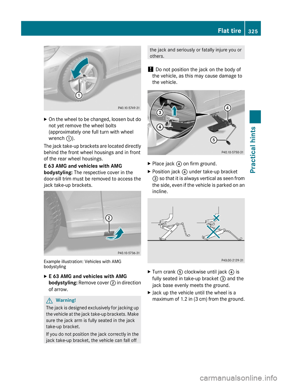
XOn the wheel to be changed, loosen but do
not yet remove the wheel bolts
(approximately one full turn with wheel
wrench :).
The jack take-up brackets are located directly
behind the front wheel housings and in front
of the rear wheel housings.
E 63 AMG and vehicles with AMG
bodystyling: The respective cover in the
door-sill trim must be removed to access the
jack take-up brackets.
Example illustration: Vehicles with AMGbodystyling
XE 63 AMG and vehicles with AMG
bodystyling: Remove cover ; in direction
of arrow.
GWarning!
The jack is designed exclusively for jacking up
the vehicle at the jack take-up brackets. Make
sure the jack arm is fully seated in the jack
take-up bracket.
If you do not position the jack correctly in the
jack take-up bracket, the vehicle can fall off
the jack and seriously or fatally injure you or
others.
! Do not position the jack on the body of
the vehicle, as this may cause damage to
the vehicle.
XPlace jack ? on firm ground.XPosition jack ? under take-up bracket
= so that it is always vertical as seen from
the side, even if the vehicle is parked on an
incline.
XTurn crank A clockwise until jack ? is
fully seated in take-up bracket = and the
jack base evenly meets the ground.
XJack up the vehicle until the wheel is a
maximum of 1.2 in (3 cm) from the ground.
Flat tire325Practical hints212_AKB; 2; 41, en-USd2ureepe,Version: 2.11.8.12009-07-17T09:14:21+02:00 - Seite 325Z
Page 342 of 372
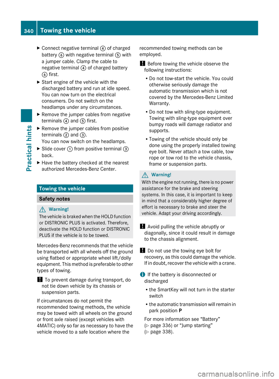
XConnect negative terminal ? of charged
battery B with negative terminal A with
a jumper cable. Clamp the cable to
negative terminal ? of charged battery
B first.XStart engine of the vehicle with the
discharged battery and run at idle speed.
You can now turn on the electrical
consumers. Do not switch on the
headlamps under any circumstances.XRemove the jumper cables from negative
terminals ? and A first.XRemove the jumper cables from positive
terminals ; and =.
You can now switch on the headlamps.XSlide cover : from positive terminal =
back.XHave the battery checked at the nearest
authorized Mercedes-Benz Center.
Towing the vehicle
Safety notes
GWarning!
The vehicle is braked when the HOLD function
or DISTRONIC PLUS is activated. Therefore,
deactivate the HOLD function or DISTRONIC
PLUS if the vehicle is to be towed.
Mercedes-Benz recommends that the vehicle
be transported with all wheels off the ground
using flatbed or appropriate wheel lift/dolly
equipment. This method is preferable to other
types of towing.
! To prevent damage during transport, do
not tie down vehicle by its chassis or
suspension parts.
If circumstances do not permit the
recommended towing methods, the vehicle
may be towed with all wheels on the ground
or front axle raised (except vehicles with
4MATIC) only so far as necessary to have the
vehicle moved to a safe location where the
recommended towing methods can be
employed.
! Before towing the vehicle observe the
following instructions:
R Do not tow-start the vehicle. You could
otherwise seriously damage the
automatic transmission which is not
covered by the Mercedes-Benz Limited
Warranty.
R Do not tow with sling-type equipment.
Towing with sling-type equipment over
bumpy roads will damage radiator and
supports.
R Towing of the vehicle should only be
done using the properly installed towing
eye bolt. Never attach a tow cable, tow
rope or tow rod to the vehicle chassis,
frame or suspension parts.GWarning!
With the engine not running, there is no power
assistance for the brake and steering
systems. In this case, it is important to keep
in mind that a considerably higher degree of
effort is necessary to brake and steer the
vehicle. Adapt your driving accordingly.
! Avoid pulling the vehicle abruptly or
diagonally, since it could result in damage
to the chassis alignment.
! Do not use the towing eye bolt for
recovery, as this could damage the vehicle.
If in doubt, recover the vehicle with a crane.
i If the battery is disconnected or
discharged
R the SmartKey will not turn in the starter
switch
R the automatic transmission will remain in
park position P
For more information see “Battery”
( Y page 336) or “Jump starting”
( Y page 338).
340Towing the vehiclePractical hints
212_AKB; 2; 41, en-USd2ureepe,Version: 2.11.8.12009-07-17T09:14:21+02:00 - Seite 340
Page 343 of 372
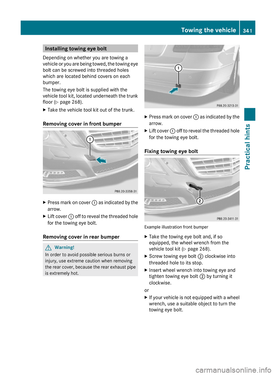
Installing towing eye bolt
Depending on whether you are towing a
vehicle or you are being towed, the towing eye
bolt can be screwed into threaded holes
which are located behind covers on each
bumper.
The towing eye bolt is supplied with the
vehicle tool kit, located underneath the trunk
floor (Y page 268).
XTake the vehicle tool kit out of the trunk.
Removing cover in front bumper
XPress mark on cover : as indicated by the
arrow.
XLift cover : off to reveal the threaded hole
for the towing eye bolt.
Removing cover in rear bumper
GWarning!
In order to avoid possible serious burns or
injury, use extreme caution when removing
the rear cover, because the rear exhaust pipe
is extremely hot.
XPress mark on cover : as indicated by the
arrow.
XLift cover : off to reveal the threaded hole
for the towing eye bolt.
Fixing towing eye bolt
Example illustration front bumper
XTake the towing eye bolt and, if so
equipped, the wheel wrench from the
vehicle tool kit (Y page 268).
XScrew towing eye bolt ; clockwise into
threaded hole to its stop.
XInsert wheel wrench into towing eye and
tighten towing eye bolt ; by turning it
clockwise.
or
XIf your vehicle is not equipped with a wheel
wrench, use a suitable object to turn the
towing eye bolt.
Towing the vehicle341Practical hints212_AKB; 2; 41, en-USd2ureepe,Version: 2.11.8.12009-07-17T09:14:21+02:00 - Seite 341Z
Page 348 of 372
Vehicle equipment
iThis Operator’s Manual describes all
features, standard or optional, potentially
available for your vehicle at the time of
purchase. Please be aware that your
vehicle might not be equipped with all
features described in this manual.
Parts service
All authorized Mercedes-Benz Centers
maintain a stock of Genuine Mercedes-Benz
Parts required for maintenance and repair
work. In addition, strategically located parts
distribution centers provide quick and
reliable parts service.
More than 300 000 different parts for
Mercedes-Benz models are available.
Genuine Mercedes-Benz Parts are subjected
to stringent quality inspections. Each part has
been specifically developed, manufactured or
selected for and adapted to Mercedes-Benz
vehicles.
Therefore, Genuine Mercedes-Benz Parts
should be installed.
! Do not use non-genuine Mercedes-Benz
parts and accessories not authorized by
Mercedes-Benz. Doing so could damage
the vehicle, which is not covered by the
Mercedes-Benz Limited Warranty. Also, it
could compromise the vehicle’s durability
or safety.
Warranty coverage
Your vehicle is covered under the terms of the
warranties printed in the Service and
Warranty Information booklet.
Your authorized Mercedes-Benz Center will
exchange or repair any defective parts
originally installed in the vehicle in
accordance with the terms of the following
warranties:
RNew Vehicle Limited Warranty
REmission System Warranty
REmission Performance Warranty
RCalifornia, Connecticut, Maine,
Massachusetts, New York, Pennsylvania,
Rhode Island, and Vermont Emission
Control Systems Warranty
RState Warranty Enforcement Laws (Lemon
Laws)
Replacement parts and accessories are
covered by the Mercedes-Benz Parts and
Accessories warranties, copies of which are
available at any authorized Mercedes-Benz
Center.
Loss of Service and Warranty
Information booklet
Should you lose your Service and Warranty
Information booklet, have an authorized
Mercedes-Benz Center arrange for a
replacement. It will be mailed to you.
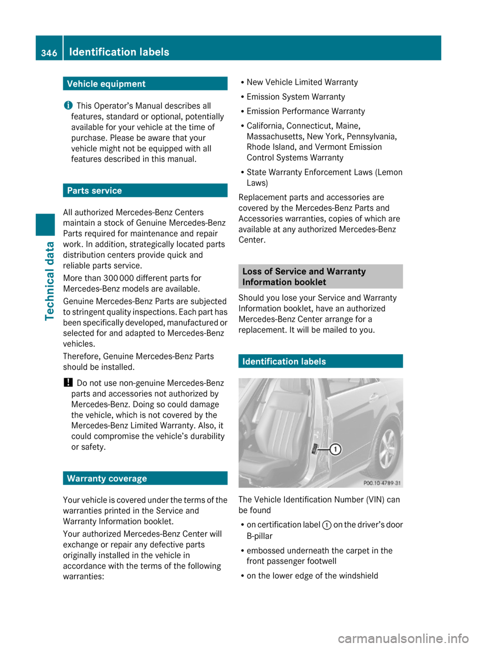
Identification labels
The Vehicle Identification Number (VIN) can
be found
Ron certification label : on the driver’s door
B-pillar
Rembossed underneath the carpet in the
front passenger footwell
Ron the lower edge of the windshield
346Identification labelsTechnical data
212_AKB; 2; 41, en-USd2ureepe,Version: 2.11.8.12009-07-17T09:14:21+02:00 - Seite 346
Page 349 of 372
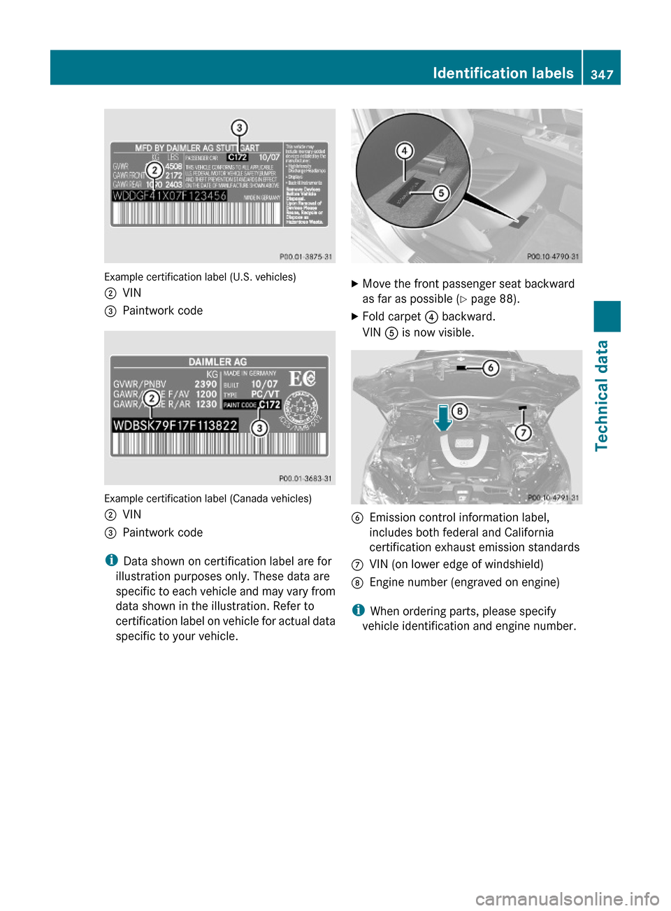
Example certification label (U.S. vehicles)
;VIN=Paintwork code
Example certification label (Canada vehicles)
;VIN=Paintwork code
iData shown on certification label are for
illustration purposes only. These data are
specific to each vehicle and may vary from
data shown in the illustration. Refer to
certification label on vehicle for actual data
specific to your vehicle.
XMove the front passenger seat backward
as far as possible (Y page 88).
XFold carpet ? backward.
VIN A is now visible.
BEmission control information label,
includes both federal and California
certification exhaust emission standards
CVIN (on lower edge of windshield)DEngine number (engraved on engine)
iWhen ordering parts, please specify
vehicle identification and engine number.
Identification labels347Technical data212_AKB; 2; 41, en-USd2ureepe,Version: 2.11.8.12009-07-17T09:14:21+02:00 - Seite 347Z