2010 MERCEDES-BENZ C350S brake
[x] Cancel search: brakePage 313 of 364
Manually unlocking the gear selector
lever
If the vehicle’s electrical system is
malfunctioning, the gear selector lever could
remain locked in park position P. In this case
the gear selector lever can be unlocked
manually, e.g. to tow the vehicle.
XEngage the parking brake.
! Do not use sharp objects to loosen the
gear selector lever cover in the center
console, as this could damage the gear
selector lever cover or the center console.
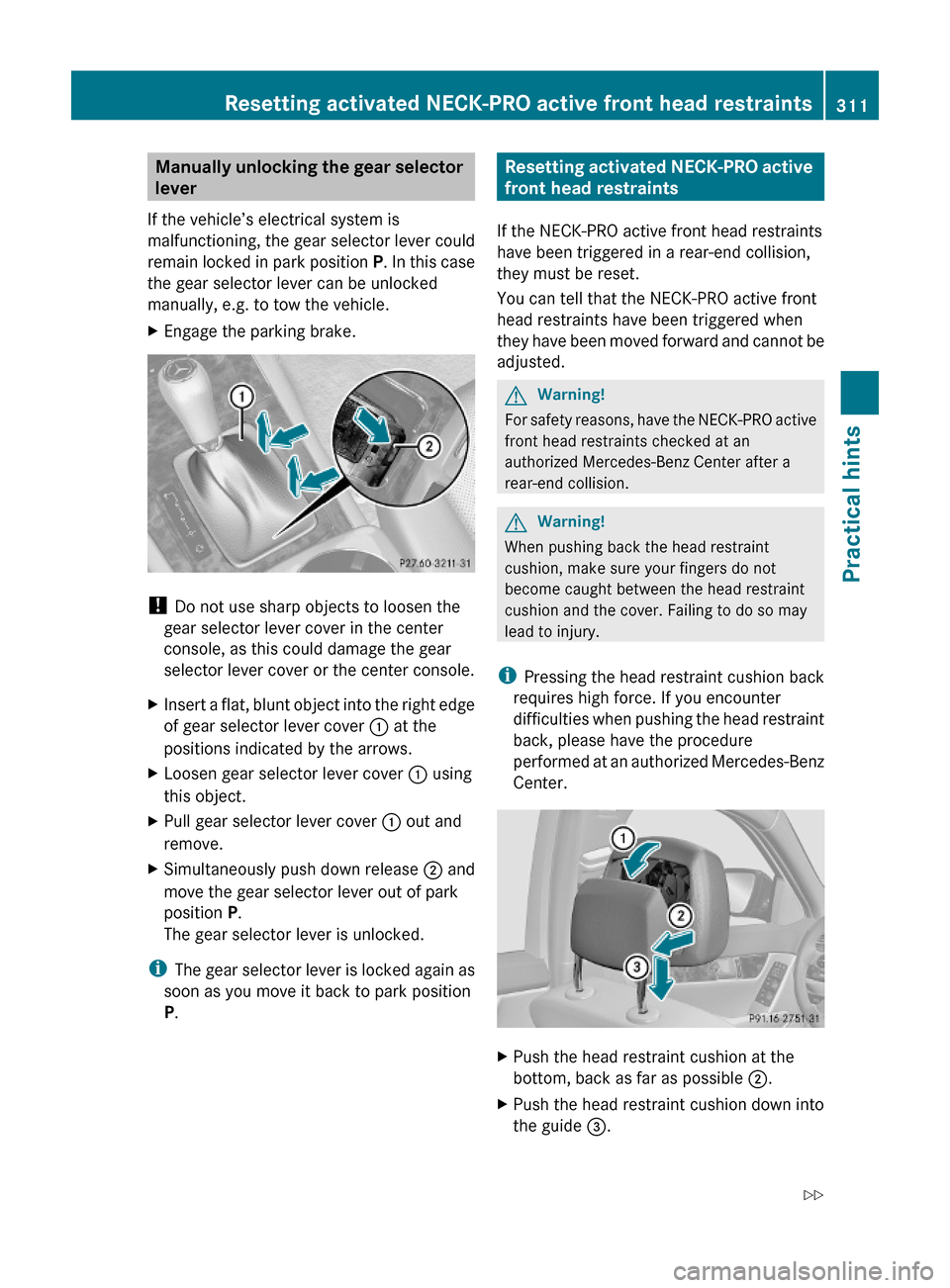
XInsert a flat, blunt object into the right edge
of gear selector lever cover : at the
positions indicated by the arrows.
XLoosen gear selector lever cover : using
this object.
XPull gear selector lever cover : out and
remove.
XSimultaneously push down release ; and
move the gear selector lever out of park
position P.
The gear selector lever is unlocked.
iThe gear selector lever is locked again as
soon as you move it back to park position
P.
Resetting activated NECK-PRO active
front head restraints
If the NECK-PRO active front head restraints
have been triggered in a rear-end collision,
they must be reset.
You can tell that the NECK-PRO active front
head restraints have been triggered when
they have been moved forward and cannot be
adjusted.
GWarning!
For safety reasons, have the NECK-PRO active
front head restraints checked at an
authorized Mercedes-Benz Center after a
rear-end collision.
GWarning!
When pushing back the head restraint
cushion, make sure your fingers do not
become caught between the head restraint
cushion and the cover. Failing to do so may
lead to injury.
iPressing the head restraint cushion back
requires high force. If you encounter
difficulties when pushing the head restraint
back, please have the procedure
performed at an authorized Mercedes-Benz
Center.
XPush the head restraint cushion at the
bottom, back as far as possible ;.
XPush the head restraint cushion down into
the guide =.
Resetting activated NECK-PRO active front head restraints311Practical hints204_AKB; 5; 23, en-USd2ureepe,Version: 2.11.8.12009-07-16T17:54:06+02:00 - Seite 311Z
Page 316 of 364
Bulbs
You can replace the following bulbs yourself:
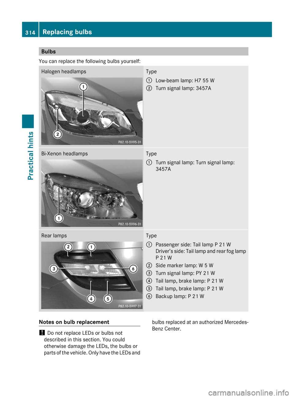
Halogen headlampsType:Low-beam lamp: H7 55 W;Turn signal lamp: 3457ABi-Xenon headlampsType:Turn signal lamp: Turn signal lamp:
3457A
Rear lampsType:Passenger side: Tail lamp P 21 W
Driver’s side: Tail lamp and rear fog lamp
P 21 W
;Side marker lamp: W 5 W=Turn signal lamp: PY 21 W?Tail lamp, brake lamp: P 21 WATail lamp, brake lamp: P 21 WBBackup lamp: P 21 WNotes on bulb replacement
! Do not replace LEDs or bulbs not
described in this section. You could
otherwise damage the LEDs, the bulbs or
parts of the vehicle. Only have the LEDs and
bulbs replaced at an authorized Mercedes-
Benz Center.
314Replacing bulbsPractical hints
204_AKB; 5; 23, en-USd2ureepe,Version: 2.11.8.12009-07-16T17:54:06+02:00 - Seite 314
Page 318 of 364
Replacing bulbs for rear lamps
Before you start to replace a bulb for a rear
lamp, do the following:
XSwitch off the ignition.XTurn the exterior lamp switch to position
$.
XOpen the trunk.
Tail lamp unit
XDriver’s side: Lift up the bottom and pull out
the trim panel covering the driver side rear
light.
XPassenger side: Open the fuse box in the
trunk (Y page 329).
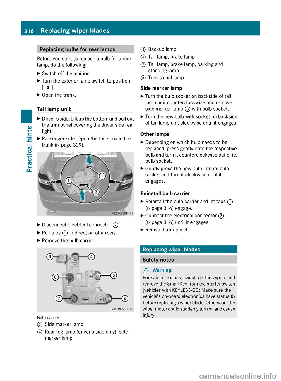
XDisconnect electrical connector ;.XPull tabs : in direction of arrows.XRemove the bulb carrier.
Bulb carrier
=Side marker lamp?Rear fog lamp (driver’s side only), side
marker lamp
ABackup lampBTail lamp, brake lampCTail lamp, brake lamp, parking and
standing lamp
DTurn signal lamp
Side marker lamp
XTurn the bulb socket on backside of tail
lamp unit counterclockwise and remove
side marker lamp = with bulb socket.
XTurn the new bulb with socket on backside
of tail lamp unit clockwise until it engages.
Other lamps
XDepending on which bulb needs to be
replaced, press gently onto the respective
bulb and turn it counterclockwise out of its
bulb socket.
XGently press the new bulb into its bulb
socket and turn it clockwise until it
engages.
Reinstall bulb carrier
XReinstall the bulb carrier and let tabs :
(Y page 316) engage.
XConnect the electrical connector ;
(Y page 316) until it engages.
XReinstall trim panel.
Replacing wiper blades
Safety notes
GWarning!
For safety reasons, switch off the wipers and
remove the SmartKey from the starter switch
(vehicles with KEYLESS-GO: Make sure the
vehicle’s on-board electronics have status 0)
before replacing a wiper blade. Otherwise, the
wiper motor could suddenly turn on and cause
injury.
316Replacing wiper bladesPractical hints
204_AKB; 5; 23, en-USd2ureepe,Version: 2.11.8.12009-07-16T17:54:06+02:00 - Seite 316
Page 320 of 364
not exceed a vehicle speed of 50 mph
(80 km/h).
Contact the nearest authorized Mercedes-
Benz Center as soon as possible to have the
spare wheel replaced with a regular road
wheel.
Never operate the vehicle with more than one
spare wheel mounted.
Do not switch off the ESP ®
when a spare
wheel is mounted.
Preparing the vehicle
XWhenever possible, park the vehicle in a
safe distance from moving traffic on a hard,
flat surface.XTurn on the hazard warning flasher.XTurn the steering wheel so that the front
wheels are in a straight-ahead position.XEngage the parking brake.XShift the automatic transmission into park
position P (manual transmission to 1st or
reverse gear R).XTurn off the engine.XRemove the SmartKey from the starter
switch.
or
XVehicles with KEYLESS-GO: Open the
driver’s door (this puts the starter switch in
position 0, same as with the SmartKey
removed from the starter switch). The
driver’s door can then be closed again.
Open doors only when conditions are safe
to do so.XVehicles with KEYLESS-GO: Remove the
KEYLESS-GO start/stop button from the
starter switch.XHave any passenger exit the vehicle at a
safe distance from the roadway. Open
doors only when conditions are safe to do
so.Mounting the spare wheel
IntroductionXPrepare the vehicle as described
( Y page 318).XTake the following out of the vehicle:
R spare wheel
R jack
R vehicle tool kit box
For information on where to find the
respective items, see “Where will I find ...?”
( Y page 268) and ( Y page 270).
i Vehicles without spare wheel are not
factory-equipped with the tools required for
a wheel change such as a jack or a wheel
wrench. Some tools required for a wheel
change are specific to your vehicle.
Contact an authorized Mercedes-Benz
Center to obtain the tools approved for
your vehicle. This section describes the
wheel change using the tools approved and
recommended for your vehicle.
Lifting the vehicle
GWarning!
When jacking up the vehicle, only use the jack
which has been specifically approved by
Mercedes-Benz for your vehicle.
The jack is designed exclusively for jacking up
the vehicle at the jack take-up brackets built
into both sides of the vehicle. Make sure the
jack arm is fully seated in the jack take-up
bracket. The jack must always be vertical
when in use, especially on inclines or
declines.
The jack is intended only for lifting the vehicle
briefly for wheel changes. It is not suited for
performing maintenance work under the
vehicle. To help avoid personal injury, use the
jack only to lift the vehicle during a wheel
change.
Never get beneath the vehicle while it is
supported by the jack. Keep hands and feet
318Flat tirePractical hints
204_AKB; 5; 23, en-USd2ureepe,Version: 2.11.8.12009-07-16T17:54:06+02:00 - Seite 318
Page 321 of 364
away from the area under the lifted vehicle.
Always lower the vehicle onto sufficient
capacity jackstands before working under the
vehicle.
Always engage the parking brake firmly and
block the wheels with wheel chocks or other
sizeable objects before raising the vehicle
with the jack. Do not disengage the parking
brake while the vehicle is raised.
Make sure that the ground on which the
vehicle is standing and where you place the
jack is solid, level and not slippery. If
necessary, use a large underlay. On slippery
surfaces, such as tiled floors, you should use
a non-slip underlay, for example a rubber mat.
Do not use wooden blocks or similar objects
to support the jack. Otherwise the jack may
not be able to achieve its load-bearing
capacity if it is not at its full height.
Never start the engine when the vehicle is
raised.
Also observe the notes on the jack.
XPrevent the vehicle from rolling away by
blocking wheels with wheel chocks or other
sizeable objects.
When your vehicle is equipped with a wheel
chock, it is included with the vehicle tool kit
(Y page 268). For information on setting up
the collapsible wheel chock, see
(Y page 269).
When changing a wheel on a level surface:
XPlace a wheel chock or other sizeable
object in front of and another wheel chock
or other sizeable object behind the wheel
that is diagonally opposite to the wheel
being changed.
Always try lifting the vehicle using the jack on
a level surface. However, should
circumstances require you to do so on a hill:
XPlace wheel chocks or other sizeable
objects on the downhill side in front of both
wheels on the side opposite to the side on
which the wheel is to be changed.
GWarning!
Only jack up the vehicle on level ground or on
slight inclines/declines. Otherwise, the
vehicle could fall off the jack and injure you or
others.
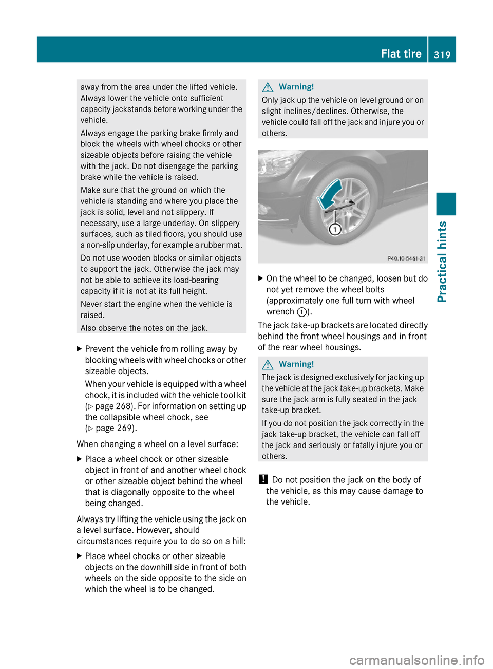
XOn the wheel to be changed, loosen but do
not yet remove the wheel bolts
(approximately one full turn with wheel
wrench :).
The jack take-up brackets are located directly
behind the front wheel housings and in front
of the rear wheel housings.
GWarning!
The jack is designed exclusively for jacking up
the vehicle at the jack take-up brackets. Make
sure the jack arm is fully seated in the jack
take-up bracket.
If you do not position the jack correctly in the
jack take-up bracket, the vehicle can fall off
the jack and seriously or fatally injure you or
others.
! Do not position the jack on the body of
the vehicle, as this may cause damage to
the vehicle.
Flat tire319Practical hints204_AKB; 5; 23, en-USd2ureepe,Version: 2.11.8.12009-07-16T17:54:06+02:00 - Seite 319Z
Page 326 of 364
of the other vehicle, provide jump start
power by an external battery or starter
pack.
RJump starting should only be performed
when the engine and catalytic converter
are cold.
RDo not jump start the engine or charge the
battery if the battery is frozen. Let the
battery thaw out first.
ROnly jump start from batteries with the
same voltage rating (12 V). Jump starting
with a more powerful battery could damage
the vehicle’s electrical system. Such
damage will not be covered by the
Mercedes-Benz Limited Warranty.
ROnly use jumper cables with sufficient
cross-section and insulated terminal
clamps.
RAlways make sure the jumper cables are
not on or near pulleys, fans or other parts
that move when an engine is started or
running.
RShould the battery be drained completely,
let the donating power source charge the
vehicle for several minutes before
reattempting the starting process.
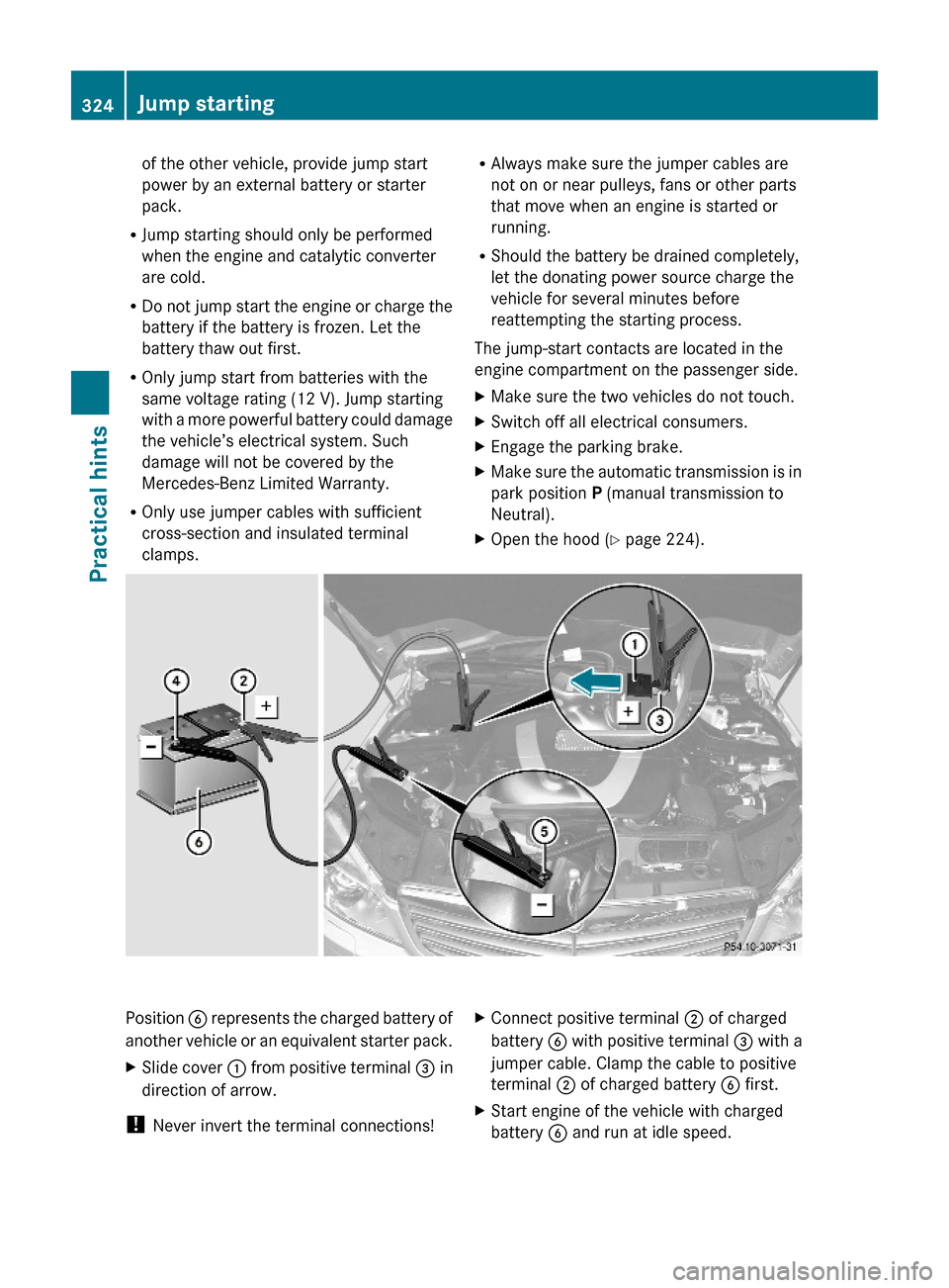
The jump-start contacts are located in the
engine compartment on the passenger side.
XMake sure the two vehicles do not touch.XSwitch off all electrical consumers.XEngage the parking brake.XMake sure the automatic transmission is in
park position P (manual transmission to
Neutral).
XOpen the hood (Y page 224).Position B represents the charged battery of
another vehicle or an equivalent starter pack.
XSlide cover : from positive terminal = in
direction of arrow.
! Never invert the terminal connections!
XConnect positive terminal ; of charged
battery B with positive terminal = with a
jumper cable. Clamp the cable to positive
terminal ; of charged battery B first.
XStart engine of the vehicle with charged
battery B and run at idle speed.
324Jump startingPractical hints
204_AKB; 5; 23, en-USd2ureepe,Version: 2.11.8.12009-07-16T17:54:06+02:00 - Seite 324
Page 327 of 364
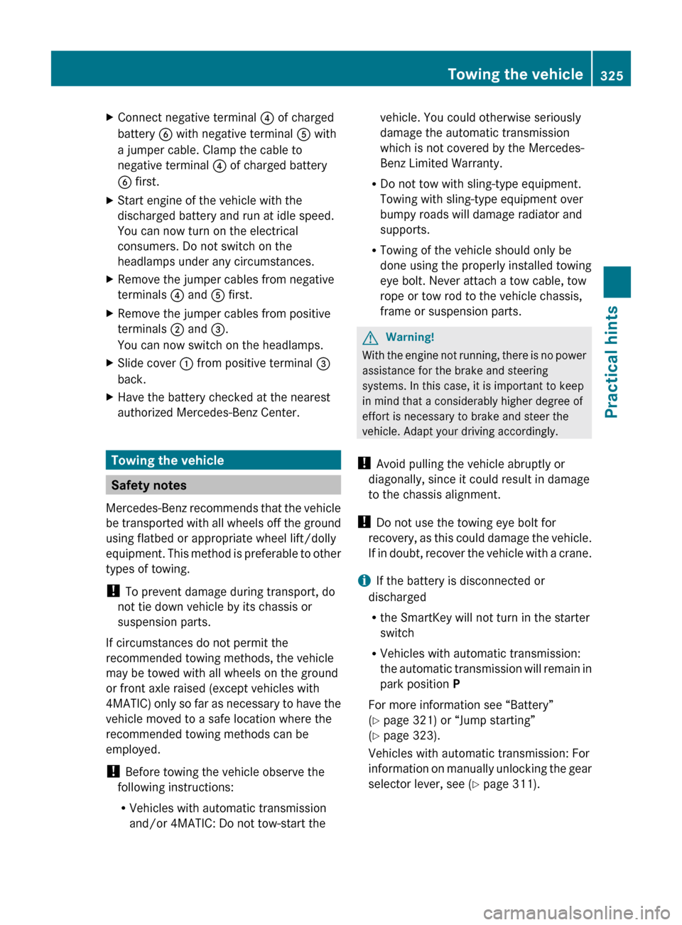
XConnect negative terminal ? of charged
battery B with negative terminal A with
a jumper cable. Clamp the cable to
negative terminal ? of charged battery
B first.XStart engine of the vehicle with the
discharged battery and run at idle speed.
You can now turn on the electrical
consumers. Do not switch on the
headlamps under any circumstances.XRemove the jumper cables from negative
terminals ? and A first.XRemove the jumper cables from positive
terminals ; and =.
You can now switch on the headlamps.XSlide cover : from positive terminal =
back.XHave the battery checked at the nearest
authorized Mercedes-Benz Center.
Towing the vehicle
Safety notes
Mercedes-Benz recommends that the vehicle
be transported with all wheels off the ground
using flatbed or appropriate wheel lift/dolly
equipment. This method is preferable to other
types of towing.
! To prevent damage during transport, do
not tie down vehicle by its chassis or
suspension parts.
If circumstances do not permit the
recommended towing methods, the vehicle
may be towed with all wheels on the ground
or front axle raised (except vehicles with
4MATIC) only so far as necessary to have the
vehicle moved to a safe location where the
recommended towing methods can be
employed.
! Before towing the vehicle observe the
following instructions:
R Vehicles with automatic transmission
and/or 4MATIC: Do not tow-start the
vehicle. You could otherwise seriously
damage the automatic transmission
which is not covered by the Mercedes-
Benz Limited Warranty.
R Do not tow with sling-type equipment.
Towing with sling-type equipment over
bumpy roads will damage radiator and
supports.
R Towing of the vehicle should only be
done using the properly installed towing
eye bolt. Never attach a tow cable, tow
rope or tow rod to the vehicle chassis,
frame or suspension parts.GWarning!
With the engine not running, there is no power
assistance for the brake and steering
systems. In this case, it is important to keep
in mind that a considerably higher degree of
effort is necessary to brake and steer the
vehicle. Adapt your driving accordingly.
! Avoid pulling the vehicle abruptly or
diagonally, since it could result in damage
to the chassis alignment.
! Do not use the towing eye bolt for
recovery, as this could damage the vehicle.
If in doubt, recover the vehicle with a crane.
i If the battery is disconnected or
discharged
R the SmartKey will not turn in the starter
switch
R Vehicles with automatic transmission:
the automatic transmission will remain in
park position P
For more information see “Battery”
( Y page 321) or “Jump starting”
( Y page 323).
Vehicles with automatic transmission: For
information on manually unlocking the gear
selector lever, see ( Y page 311).
Towing the vehicle325Practical hints204_AKB; 5; 23, en-USd2ureepe,Version: 2.11.8.12009-07-16T17:54:06+02:00 - Seite 325Z
Page 329 of 364

Removing towing eye boltXLoosen towing eye bolt ; by turning it
counterclockwise.XUnscrew towing eye bolt ;.XStore the towing eye bolt ; and wheel
wrench back into the vehicle tool kit.
Towing with all wheels on the ground
GWarning!
If circumstances require towing the vehicle
with all wheels on the ground, always tow with
a tow bar if:
R the engine will not run
R there is a malfunction in the brake system
R there is a malfunction in the power supply
or in the vehicle’s electrical system
This is necessary to adequately control the
towed vehicle.
Prior to towing the vehicle with all wheels on
the ground, make sure the SmartKey is in
starter switch position 2.
If the SmartKey is left in the starter switch
position 0 for an extended period of time, it
can no longer be turned in the switch. In this
case, the steering is locked. To unlock,
remove SmartKey from starter switch and
reinsert.
GWarning!
With the engine not running, there is no power
assistance for the brake and steering
systems. In this case, it is important to keep
in mind that a considerably higher degree of
effort is necessary to brake and steer the
vehicle. Adapt your driving accordingly.
XMake sure the ignition is switched on.XWith the vehicle at a standstill, depress the
brake pedal and keep it pressed.XVehicles with manual transmission: Shift
the manual transmission into the neutral
position (no gear selected).
or
XVehicles with automatic transmission: Shift
the automatic transmission into neutral
position N.XRelease the brake pedal.XIf engaged, release the parking brake.XSwitch on the hazard warning flasher
( Y page 93).
!
The vehicle may be towed only for
distances up to 30 miles (50 km) and at a
speed not to exceed 30 mph (50 km/h).
i While being towed with the hazard
warning flasher in use, use the combination
switch in the usual manner to signal turns.
Only the selected turn signal will operate.
Upon canceling the turn signal, the hazard
warning flasher will operate again.
Towing with front axle raised
! The vehicle may be towed only for
distances up to 30 miles (50 km) and at a
speed not to exceed 30 mph (50 km/h).
! Vehicles with 4MATIC: Do not tow with
one axle raised. Doing so could damage the
transfer case, which is not covered by the
Mercedes-Benz Limited Warranty.
All wheels must be on or off the ground.
Observe instructions for towing the vehicle
with all wheels on the ground.
XMake sure the ignition is switched on.XWith the vehicle at a standstill, depress the
brake pedal and keep it pressed.Towing the vehicle327Practical hints204_AKB; 5; 23, en-USd2ureepe,Version: 2.11.8.12009-07-16T17:54:06+02:00 - Seite 327Z