2010 MERCEDES-BENZ C300LUX 4MATIC Tool kit
[x] Cancel search: Tool kitPage 20 of 364

U
Uniform Tire Quality Grading
Standards .................................. 244, 252
Units
Selecting speedometer display
mode ............................................. 131
Unleaded gasoline, premium ........... 354
Unlocking the vehicle
KEYLESS-GO .................................... 71
Manually ........................................ 309
SmartKey ......................................... 70
Upholstery, cleaning ......................... 266
Useful features .................................. 207
V
Valet locking ........................................ 77
Vehicle
Battery ........................................... 321
Care ............................................... 260
Control system .............................. 118
Identification Number (VIN) ...........332
Locking/unlocking ........................... 70
Lowering (wheel change) ...............321
Modifications and alterations,
Operating safety .............................. 22
Towing ........................................... 325
Unlocking/locking manually ..........309
Vehicle dimensions
see Vehicle specification
Vehicle Identification Number
(VIN) ................................................... 332
Vehicle jack see Jack
Vehicle lighting .................................... 90
Vehicle loading
Cargo tie-down rings ...................... 203
Instructions .................................... 202
Load limit ....................................... 239
Roof rack ....................................... 203
Split rear seat bench .....................204
Terminology ................................... 250
Vehicle maximum load on the tire ... 252
Vehicle specification
C 250 ............................................. 334
C 250 4MATIC ............................... 335
C 250 4MATIC Sport ...................... 336
C 250 Sport ................................... 334
C 300 ............................................. 337
C 300 4MATIC ............................... 339
C 300 4MATIC Sport ...................... 340
C 300 Sport ................................... 338
C 350 ............................................. 341
C 350 4MATIC ............................... 343
C 350 Sport ................................... 342
C 63 AMG ...................................... 343
Vehicle status message memory .... 129
Vehicle tool kit .................................. 268
Vehicle washing see Vehicle care
Vehicle weights
see Vehicle specification
W
Warning sounds
Driver’s or passenger’s seat belt .....51
Parking brake ................................ 281
Parktronic system ..........................187
Seat belt telltale ............................ 301
Warranty coverage ............................ 332
Washer and headlamp cleaning
system ................................................ 358
Washer fluid
Mixing ratio .................................... 358
Refilling .......................................... 228
Washing the vehicle .......................... 260
Wear pattern (tires) .......................... 245
Weights (vehicle) see Vehicle specification
Wheel
Changing ....................................... 317
Removing ....................................... 320
Spare ............................................. 317
Tightening torque ........................... 321
Wheels, sizes ..................................... 344
Wheels, Tires and .............................. 229
Window curtain air bags ..................... 42
Windows see Power windows
Windows, cleaning ............................ 264
Windshield
Cleaning wiper blades .................... 264
Defogging ...................................... 195
18Index204_AKB; 5; 23, en-USd2ureepe,Version: 2.11.8.12009-07-16T17:54:06+02:00 - Seite 18
Page 270 of 364
Vehicle equipment
iThis Operator’s Manual describes all
features, standard or optional, potentially
available for your vehicle at the time of
purchase. Please be aware that your
vehicle might not be equipped with all
features described in this manual.
Where will I find ...?
First aid kit
iCheck expiration dates and contents for
completeness at least once a year and
replace missing/expired items.
Depending on the equipment configuration,
the first-aid kit will be located either in the
open storage department in the trunk or
behind the cover panel on the left-hand side
of the trunk.
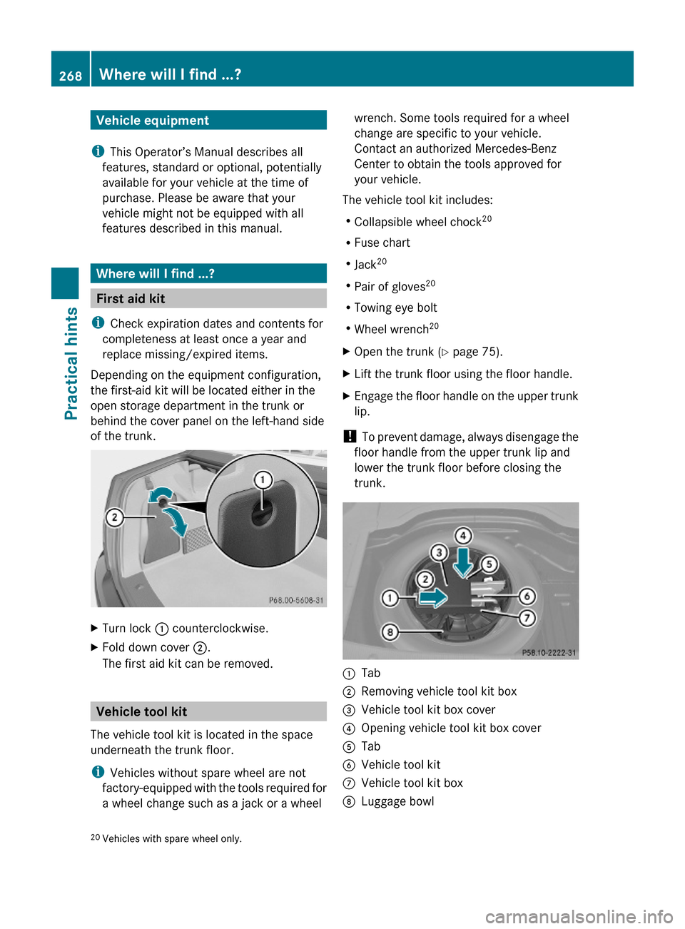
XTurn lock : counterclockwise.XFold down cover ;.
The first aid kit can be removed.
Vehicle tool kit
The vehicle tool kit is located in the space
underneath the trunk floor.
iVehicles without spare wheel are not
factory-equipped with the tools required for
a wheel change such as a jack or a wheel
wrench. Some tools required for a wheel
change are specific to your vehicle.
Contact an authorized Mercedes-Benz
Center to obtain the tools approved for
your vehicle.
The vehicle tool kit includes:
RCollapsible wheel chock20
RFuse chart
RJack20
RPair of gloves20
RTowing eye bolt
RWheel wrench20
XOpen the trunk (Y page 75).XLift the trunk floor using the floor handle.XEngage the floor handle on the upper trunk
lip.
! To prevent damage, always disengage the
floor handle from the upper trunk lip and
lower the trunk floor before closing the
trunk.
:Tab;Removing vehicle tool kit box=Vehicle tool kit box cover?Opening vehicle tool kit box coverATabBVehicle tool kitCVehicle tool kit boxDLuggage bowl20Vehicles with spare wheel only.268Where will I find ...?Practical hints
204_AKB; 5; 23, en-USd2ureepe,Version: 2.11.8.12009-07-16T17:54:06+02:00 - Seite 268
Page 271 of 364
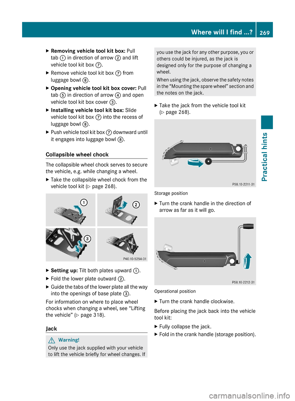
XRemoving vehicle tool kit box: Pull
tab : in direction of arrow ; and lift
vehicle tool kit box C.
XRemove vehicle tool kit box C from
luggage bowl D.
XOpening vehicle tool kit box cover: Pull
tab A in direction of arrow ? and open
vehicle tool kit box cover =.
XInstalling vehicle tool kit box: Slide
vehicle tool kit box C into the recess of
luggage bowl D.
XPush vehicle tool kit box C downward until
it engages into luggage bowl D.
Collapsible wheel chock
The collapsible wheel chock serves to secure
the vehicle, e.g. while changing a wheel.
XTake the collapsible wheel chock from the
vehicle tool kit (Y page 268).
XSetting up: Tilt both plates upward :.XFold the lower plate outward ;.XGuide the tabs of the lower plate all the way
into the openings of base plate =.
For information on where to place wheel
chocks when changing a wheel, see “Lifting
the vehicle” (Y page 318).
Jack
GWarning!
Only use the jack supplied with your vehicle
to lift the vehicle briefly for wheel changes. If
you use the jack for any other purpose, you or
others could be injured, as the jack is
designed only for the purpose of changing a
wheel.
When using the jack, observe the safety notes
in the “Mounting the spare wheel” section and
the notes on the jack.
XTake the jack from the vehicle tool kit
(Y page 268).
Storage position
XTurn the crank handle in the direction of
arrow as far as it will go.
Operational position
XTurn the crank handle clockwise.
Before placing the jack back into the vehicle
tool kit:
XFully collapse the jack.XFold in the crank handle (storage position).Where will I find ...?269Practical hints204_AKB; 5; 23, en-USd2ureepe,Version: 2.11.8.12009-07-16T17:54:06+02:00 - Seite 269Z
Page 320 of 364
not exceed a vehicle speed of 50 mph
(80 km/h).
Contact the nearest authorized Mercedes-
Benz Center as soon as possible to have the
spare wheel replaced with a regular road
wheel.
Never operate the vehicle with more than one
spare wheel mounted.
Do not switch off the ESP ®
when a spare
wheel is mounted.
Preparing the vehicle
XWhenever possible, park the vehicle in a
safe distance from moving traffic on a hard,
flat surface.XTurn on the hazard warning flasher.XTurn the steering wheel so that the front
wheels are in a straight-ahead position.XEngage the parking brake.XShift the automatic transmission into park
position P (manual transmission to 1st or
reverse gear R).XTurn off the engine.XRemove the SmartKey from the starter
switch.
or
XVehicles with KEYLESS-GO: Open the
driver’s door (this puts the starter switch in
position 0, same as with the SmartKey
removed from the starter switch). The
driver’s door can then be closed again.
Open doors only when conditions are safe
to do so.XVehicles with KEYLESS-GO: Remove the
KEYLESS-GO start/stop button from the
starter switch.XHave any passenger exit the vehicle at a
safe distance from the roadway. Open
doors only when conditions are safe to do
so.Mounting the spare wheel
IntroductionXPrepare the vehicle as described
( Y page 318).XTake the following out of the vehicle:
R spare wheel
R jack
R vehicle tool kit box
For information on where to find the
respective items, see “Where will I find ...?”
( Y page 268) and ( Y page 270).
i Vehicles without spare wheel are not
factory-equipped with the tools required for
a wheel change such as a jack or a wheel
wrench. Some tools required for a wheel
change are specific to your vehicle.
Contact an authorized Mercedes-Benz
Center to obtain the tools approved for
your vehicle. This section describes the
wheel change using the tools approved and
recommended for your vehicle.
Lifting the vehicle
GWarning!
When jacking up the vehicle, only use the jack
which has been specifically approved by
Mercedes-Benz for your vehicle.
The jack is designed exclusively for jacking up
the vehicle at the jack take-up brackets built
into both sides of the vehicle. Make sure the
jack arm is fully seated in the jack take-up
bracket. The jack must always be vertical
when in use, especially on inclines or
declines.
The jack is intended only for lifting the vehicle
briefly for wheel changes. It is not suited for
performing maintenance work under the
vehicle. To help avoid personal injury, use the
jack only to lift the vehicle during a wheel
change.
Never get beneath the vehicle while it is
supported by the jack. Keep hands and feet
318Flat tirePractical hints
204_AKB; 5; 23, en-USd2ureepe,Version: 2.11.8.12009-07-16T17:54:06+02:00 - Seite 318
Page 321 of 364
away from the area under the lifted vehicle.
Always lower the vehicle onto sufficient
capacity jackstands before working under the
vehicle.
Always engage the parking brake firmly and
block the wheels with wheel chocks or other
sizeable objects before raising the vehicle
with the jack. Do not disengage the parking
brake while the vehicle is raised.
Make sure that the ground on which the
vehicle is standing and where you place the
jack is solid, level and not slippery. If
necessary, use a large underlay. On slippery
surfaces, such as tiled floors, you should use
a non-slip underlay, for example a rubber mat.
Do not use wooden blocks or similar objects
to support the jack. Otherwise the jack may
not be able to achieve its load-bearing
capacity if it is not at its full height.
Never start the engine when the vehicle is
raised.
Also observe the notes on the jack.
XPrevent the vehicle from rolling away by
blocking wheels with wheel chocks or other
sizeable objects.
When your vehicle is equipped with a wheel
chock, it is included with the vehicle tool kit
(Y page 268). For information on setting up
the collapsible wheel chock, see
(Y page 269).
When changing a wheel on a level surface:
XPlace a wheel chock or other sizeable
object in front of and another wheel chock
or other sizeable object behind the wheel
that is diagonally opposite to the wheel
being changed.
Always try lifting the vehicle using the jack on
a level surface. However, should
circumstances require you to do so on a hill:
XPlace wheel chocks or other sizeable
objects on the downhill side in front of both
wheels on the side opposite to the side on
which the wheel is to be changed.
GWarning!
Only jack up the vehicle on level ground or on
slight inclines/declines. Otherwise, the
vehicle could fall off the jack and injure you or
others.
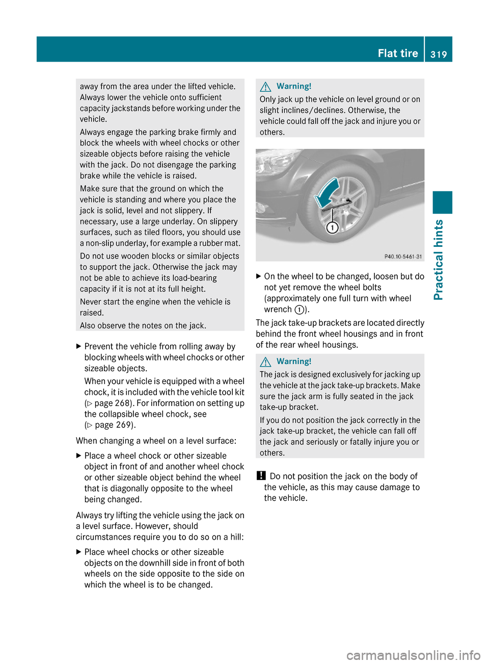
XOn the wheel to be changed, loosen but do
not yet remove the wheel bolts
(approximately one full turn with wheel
wrench :).
The jack take-up brackets are located directly
behind the front wheel housings and in front
of the rear wheel housings.
GWarning!
The jack is designed exclusively for jacking up
the vehicle at the jack take-up brackets. Make
sure the jack arm is fully seated in the jack
take-up bracket.
If you do not position the jack correctly in the
jack take-up bracket, the vehicle can fall off
the jack and seriously or fatally injure you or
others.
! Do not position the jack on the body of
the vehicle, as this may cause damage to
the vehicle.
Flat tire319Practical hints204_AKB; 5; 23, en-USd2ureepe,Version: 2.11.8.12009-07-16T17:54:06+02:00 - Seite 319Z
Page 328 of 364
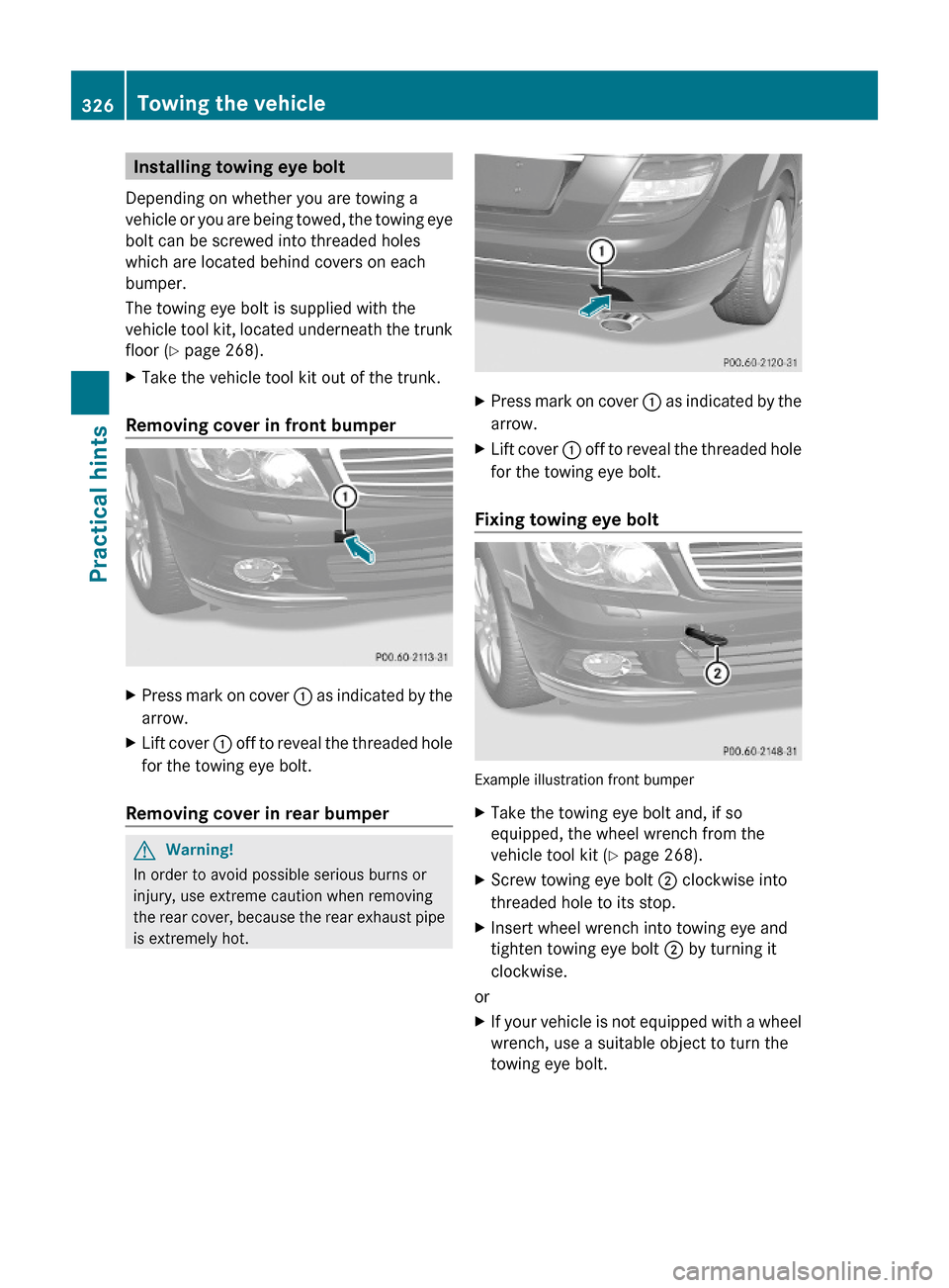
Installing towing eye bolt
Depending on whether you are towing a
vehicle or you are being towed, the towing eye
bolt can be screwed into threaded holes
which are located behind covers on each
bumper.
The towing eye bolt is supplied with the
vehicle tool kit, located underneath the trunk
floor (Y page 268).
XTake the vehicle tool kit out of the trunk.
Removing cover in front bumper
XPress mark on cover : as indicated by the
arrow.
XLift cover : off to reveal the threaded hole
for the towing eye bolt.
Removing cover in rear bumper
GWarning!
In order to avoid possible serious burns or
injury, use extreme caution when removing
the rear cover, because the rear exhaust pipe
is extremely hot.
XPress mark on cover : as indicated by the
arrow.
XLift cover : off to reveal the threaded hole
for the towing eye bolt.
Fixing towing eye bolt
Example illustration front bumper
XTake the towing eye bolt and, if so
equipped, the wheel wrench from the
vehicle tool kit (Y page 268).
XScrew towing eye bolt ; clockwise into
threaded hole to its stop.
XInsert wheel wrench into towing eye and
tighten towing eye bolt ; by turning it
clockwise.
or
XIf your vehicle is not equipped with a wheel
wrench, use a suitable object to turn the
towing eye bolt.
326Towing the vehiclePractical hints
204_AKB; 5; 23, en-USd2ureepe,Version: 2.11.8.12009-07-16T17:54:06+02:00 - Seite 326
Page 329 of 364

Removing towing eye boltXLoosen towing eye bolt ; by turning it
counterclockwise.XUnscrew towing eye bolt ;.XStore the towing eye bolt ; and wheel
wrench back into the vehicle tool kit.
Towing with all wheels on the ground
GWarning!
If circumstances require towing the vehicle
with all wheels on the ground, always tow with
a tow bar if:
R the engine will not run
R there is a malfunction in the brake system
R there is a malfunction in the power supply
or in the vehicle’s electrical system
This is necessary to adequately control the
towed vehicle.
Prior to towing the vehicle with all wheels on
the ground, make sure the SmartKey is in
starter switch position 2.
If the SmartKey is left in the starter switch
position 0 for an extended period of time, it
can no longer be turned in the switch. In this
case, the steering is locked. To unlock,
remove SmartKey from starter switch and
reinsert.
GWarning!
With the engine not running, there is no power
assistance for the brake and steering
systems. In this case, it is important to keep
in mind that a considerably higher degree of
effort is necessary to brake and steer the
vehicle. Adapt your driving accordingly.
XMake sure the ignition is switched on.XWith the vehicle at a standstill, depress the
brake pedal and keep it pressed.XVehicles with manual transmission: Shift
the manual transmission into the neutral
position (no gear selected).
or
XVehicles with automatic transmission: Shift
the automatic transmission into neutral
position N.XRelease the brake pedal.XIf engaged, release the parking brake.XSwitch on the hazard warning flasher
( Y page 93).
!
The vehicle may be towed only for
distances up to 30 miles (50 km) and at a
speed not to exceed 30 mph (50 km/h).
i While being towed with the hazard
warning flasher in use, use the combination
switch in the usual manner to signal turns.
Only the selected turn signal will operate.
Upon canceling the turn signal, the hazard
warning flasher will operate again.
Towing with front axle raised
! The vehicle may be towed only for
distances up to 30 miles (50 km) and at a
speed not to exceed 30 mph (50 km/h).
! Vehicles with 4MATIC: Do not tow with
one axle raised. Doing so could damage the
transfer case, which is not covered by the
Mercedes-Benz Limited Warranty.
All wheels must be on or off the ground.
Observe instructions for towing the vehicle
with all wheels on the ground.
XMake sure the ignition is switched on.XWith the vehicle at a standstill, depress the
brake pedal and keep it pressed.Towing the vehicle327Practical hints204_AKB; 5; 23, en-USd2ureepe,Version: 2.11.8.12009-07-16T17:54:06+02:00 - Seite 327Z
Page 330 of 364
XVehicles with manual transmission: Shift
the manual transmission into the neutral
position (no gear selected).
or
XVehicles with automatic transmission: Shift
the automatic transmission into neutral
position N.XRelease the brake pedal.XIf engaged, release the parking brake.XSwitch off the automatic central locking
( Y page 135).XSwitch off the ignition and leave the
SmartKey in the starter switch.XSwitch on the hazard warning flasher
( Y page 93).
!
Vehicles without 4MATIC:
Because the ESP ®
operates automatically,
the engine and ignition must be shut off
(SmartKey in starter switch position 0 or
1 or KEYLESS-GO start/stop button in
position 0 or 1) when the vehicle is being
towed with the front axle raised.
Active braking action through the ESP ®
may otherwise seriously damage the brake
system which is not covered by the
Mercedes-Benz Limited Warranty.
Fuses
Introduction
The electrical fuses in your vehicle serve to
switch off malfunctioning power circuits.
If a fuse is blown, the components and
systems secured by that fuse will stop
operating.
GWarning!
Only use fuses approved by Mercedes-Benz
with the specified amperage for the system in
question and do not attempt to repair or
bridge a blown fuse. Using other than
approved fuses or using repaired or bridged
fuses may cause an overload leading to a fire,
and/or cause damage to electrical
components and/or systems. Have the cause
determined and remedied by an authorized
Mercedes-Benz Center.
A blown fuse must be replaced by an
appropriate spare fuse (recognizable by its
color or the fuse rating given on the fuse) of
the amperage recommended in the fuse
chart. Any Mercedes-Benz Center will be glad
to advise you on this subject.
i In case of a blown fuse contact Roadside
Assistance or an authorized Mercedes-
Benz Center.
If a newly inserted fuse blows again, have the
cause determined and rectified by an
authorized Mercedes-Benz Center.
The fuse chart is located in the trunk with the
vehicle tool kit ( Y page 268). The fuse chart
explains the fuse allocation and fuse
amperages.
Before replacing fuses
XEngage the parking brake.XMake sure the automatic transmission is in
park position P (manual transmission to
Neutral).XSwitch off all electrical consumers.XTurn off the engine.XRemove the SmartKey from the starter
switch.XVehicles with KEYLESS-GO: Open the
driver’s door (this puts the starter switch in
position 0, same as with the SmartKey
removed from the starter switch). The
driver’s door then can be closed again.
Fuse box in passenger compartment
! Do not use sharp objects such as a
screwdriver to open the fuse box cover in
the dashboard. You could damage the fuse
box cover or the dashboard.
328FusesPractical hints
204_AKB; 5; 23, en-USd2ureepe,Version: 2.11.8.12009-07-16T17:54:06+02:00 - Seite 328