2010 MERCEDES-BENZ C300 4MATIC spare wheel
[x] Cancel search: spare wheelPage 253 of 364
GAWR (Gross Axle Weight Rating)
The GAWR is the maximum permissible axle
weight. The gross vehicle weight on each axle
must never exceed the GAWR for the front
and rear axle indicated on the certification
label located on the driver’s door B-pillar.
GVW (Gross Vehicle Weight)
The GVW comprises the weight of the vehicle
including fuel, tools, spare wheel, installed
accessories, passengers and cargo and, if
applicable, trailer tongue load. The GVW must
never exceed the GVWR indicated on the
certification label located on the driver’s door
B-pillar.
GVWR (Gross Vehicle Weight Rating)
This is the maximum permissible vehicle
weight of the fully loaded vehicle (weight of
the vehicle including all options, passengers,
fuel, and cargo and, if applicable, trailer
tongue load). It is indicated on the
certification label located on the driver’s door
B-pillar.
Kilopascal (kPa)
Metric unit for air pressure. There are 6.9 kPa
to 1 psi; another metric unit for air pressure
is bar. There are 100 kilopascals (kPa) to
1 bar.
Load index
Numerical code associated with the
maximum load a tire can support.
Maximum load rating
The maximum load in kilograms and pounds
that can be carried by the tire.
Maximum loaded vehicle weight
The sum of curb weight, accessory weight,
total load limit, and production options
weight.
Maximum permissible tire inflation
pressure
This number is the greatest amount of air
pressure that should ever be put in the tire.
Normal occupant weight
The number of occupants the vehicle is
designed to seat, multiplied by 68 kilograms
(150 lb).
Occupant distribution
The distribution of occupants in a vehicle at
their designated seating positions.
Production options weight
The combined weight of those installed
regular production options weighing over
5 lbs (2.3 kilograms) in excess of those
standard items which they replace, not
previously considered in curb weight or
accessory weight, including heavy duty
brakes, ride levelers, roof rack, heavy duty
battery, and special trim.
PSI (Pounds per square inch)
A standard unit of measure for air pressure.
Recommended tire inflation pressure
The recommended tire inflation pressure for
normal driving conditions is listed on the Tire
and Loading Information placard located on
the driver’s door B-pillar. It provides best
handling, tread life and riding comfort.
Supplemental information pertaining to
special driving situations can be found on the
tire inflation pressure label on the inside of
the fuel filler flap.
Rim
A metal support for a tire or a tire and tube
assembly upon which the tire beads are
seated.
Tires and wheels251Operation204_AKB; 5; 23, en-USd2ureepe,Version: 2.11.8.12009-07-16T17:54:06+02:00 - Seite 251Z
Page 254 of 364
Sidewall
The portion of a tire between the tread and
the bead.
TIN (Tire Identification Number)
Unique identifier which facilitates efforts by
tire manufacturers to notify purchasers in
recall situations or other safety matters
concerning tires and gives purchasers the
means to easily identify such tires. The TIN is
comprised of “Manufacturer’s identification
mark”, “Tire size”, “Tire type code” and “Date
of manufacture”.
Tire ply composition and material used
This indicates the number of plies or the
number of layers of rubber-coated fabric in
the tire tread and sidewall. Tire
manufacturers also must indicate the ply
materials in the tire and sidewall, which
include steel, nylon, polyester, and others.
Tire speed rating
Part of tire designation (speed symbol);
indicates the speed range for which a tire is
approved.
Total load limit
Rated cargo and luggage load plus
68 kilograms (150 lb) times the vehicle’s
designated seating capacity.
Traction
The adhesive friction of a tire on a surface on
which it moves. The amount of grip provided.
Tread
The portion of a tire that comes into contact
with the road.
Treadwear indicators
Narrow bands, sometimes called “wear bars”
that show across the tread of a tire when only
1 / 16 in (1.6 mm) of tread remains.
Uniform Tire Quality Grading Standards
A tire information system that provides
consumers with ratings for a tire’s traction,
temperature and treadwear. Ratings are
determined by tire manufacturers using U.S.
government testing procedures. The ratings
are molded into the sidewall of the tire.
Vehicle maximum load on the tire
Load on an individual tire that is determined
by distributing to each axle its share of the
maximum loaded vehicle weight and dividing
it by two.
Winter driving
General information
Have your vehicle winterized at an authorized
Mercedes-Benz Center.
Winter tires
GWarning!
Winter tires with a tread depth of less than
1 / 6 in (4 mm) must be replaced. They are no
longer suitable for winter operation.
GWarning!
If you use your spare wheel when winter tires
are fitted on the other wheels, be aware that
the difference in tire characteristics may very
well impair turning stability and that overall
driving stability may be reduced. Adapt your
driving style accordingly.
Have the spare wheel replaced by a regular
road wheel with a winter tire at the nearest
authorized Mercedes-Benz Center.
252Winter drivingOperation
204_AKB; 5; 23, en-USd2ureepe,Version: 2.11.8.12009-07-16T17:54:06+02:00 - Seite 252
Page 255 of 364
Always use winter tires at temperatures
below 45‡ (7†) and whenever wintry road
conditions prevail. Not all M+S rated tires
provide special winter performance. Make
sure the tires you use show the mountain/
snowflake imarking on the tire sidewall.
These tires meet specific snow traction
performance requirements of the Rubber
Manufacturers Association (RMA) and the
Rubber Association of Canada (RAC) and
have been designed specifically for use in
snow conditions. Use of winter tires is the
only way to achieve the maximum
effectiveness of your vehicle’s driving safety
systems such as the ABS and the ESP ®
in
winter operation.
For safe handling, make sure all mounted
winter tires are of the same make and have
the same tread design.
For information on winter tires for your
vehicle model, see the “Technical data”
section ( Y page 344).
Always observe the speed rating of the winter
tires installed on your vehicle.
After installing winter tires:XCheck the tire inflation pressure and adjust
it if necessary ( Y page 232).XRestart the tire pressure loss warning
system ( Y page 233) or the Advanced Tire
Pressure Monitoring System (Y page 234).
Snow chains
! Some tire sizes do not leave adequate
clearance for snow chains. To help avoid
serious damage to your vehicle or tires,
make sure the use of snow chains is
permissible as specified in the “Technical
data” section of this Operator’s Manual.
Snow chains should only be driven on snow-
covered roads at speeds not to exceed
30 mph (50 km/h). Remove chains as soon
as possible when driving on roads without
snow.
Observe the following guidelines when using
snow chains:
R Use of snow chains is not permissible with
all wheel/tire combinations ( Y page 344).
R Use snow chains in pairs and on rear
wheels only. Follow the manufacturer’s
mounting instructions.
! If snow chains are mounted to the front
wheels, they may scrape against the body
or axle components. The tires or the vehicle
could be damaged as a result.
R Only use snow chains that are approved by
Mercedes-Benz. Any authorized Mercedes-
Benz Center will be glad to advise you on
this subject.
R Use of snow chains may be prohibited
depending on location. Always check local
and state laws before installing snow
chains.
R Do not use snow chains on the spare wheel.
i When driving with snow chains, you may
wish to switch off the ESP ®
(Y page 62)
before setting the vehicle in motion. This
will improve the vehicle’s traction.
Winter driving instructions
GWarning!
If the vehicle becomes stuck in snow, make
sure snow is kept clear of the exhaust pipe
and from around the vehicle with the engine
running. Otherwise, deadly carbon monoxide
(CO) gases may enter vehicle interior
resulting in unconsciousness and death.
To assure sufficient fresh air ventilation, open
a window slightly on the side of the vehicle
not facing the wind.
GWarning!
The outside temperature indicator is not
designed to serve as an ice-warning device
and is therefore unsuitable for that purpose.
Winter driving253Operation204_AKB; 5; 23, en-USd2ureepe,Version: 2.11.8.12009-07-16T17:54:06+02:00 - Seite 253Z
Page 270 of 364
Vehicle equipment
iThis Operator’s Manual describes all
features, standard or optional, potentially
available for your vehicle at the time of
purchase. Please be aware that your
vehicle might not be equipped with all
features described in this manual.
Where will I find ...?
First aid kit
iCheck expiration dates and contents for
completeness at least once a year and
replace missing/expired items.
Depending on the equipment configuration,
the first-aid kit will be located either in the
open storage department in the trunk or
behind the cover panel on the left-hand side
of the trunk.
XTurn lock : counterclockwise.XFold down cover ;.
The first aid kit can be removed.
Vehicle tool kit
The vehicle tool kit is located in the space
underneath the trunk floor.
iVehicles without spare wheel are not
factory-equipped with the tools required for
a wheel change such as a jack or a wheel
wrench. Some tools required for a wheel
change are specific to your vehicle.
Contact an authorized Mercedes-Benz
Center to obtain the tools approved for
your vehicle.
The vehicle tool kit includes:
RCollapsible wheel chock20
RFuse chart
RJack20
RPair of gloves20
RTowing eye bolt
RWheel wrench20
XOpen the trunk (Y page 75).XLift the trunk floor using the floor handle.XEngage the floor handle on the upper trunk
lip.
! To prevent damage, always disengage the
floor handle from the upper trunk lip and
lower the trunk floor before closing the
trunk.
:Tab;Removing vehicle tool kit box=Vehicle tool kit box cover?Opening vehicle tool kit box coverATabBVehicle tool kitCVehicle tool kit boxDLuggage bowl20Vehicles with spare wheel only.268Where will I find ...?Practical hints
204_AKB; 5; 23, en-USd2ureepe,Version: 2.11.8.12009-07-16T17:54:06+02:00 - Seite 268
Page 271 of 364
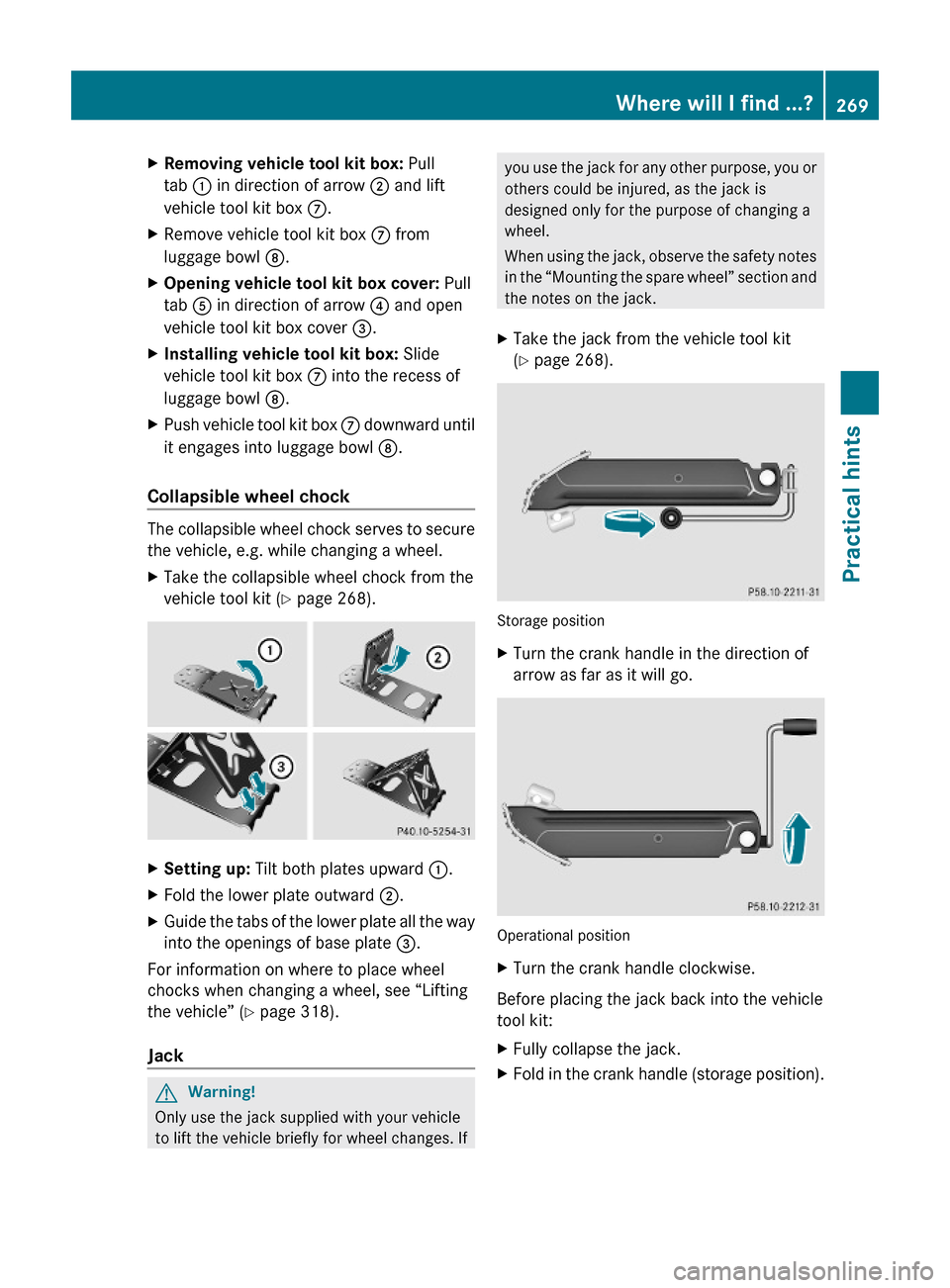
XRemoving vehicle tool kit box: Pull
tab : in direction of arrow ; and lift
vehicle tool kit box C.
XRemove vehicle tool kit box C from
luggage bowl D.
XOpening vehicle tool kit box cover: Pull
tab A in direction of arrow ? and open
vehicle tool kit box cover =.
XInstalling vehicle tool kit box: Slide
vehicle tool kit box C into the recess of
luggage bowl D.
XPush vehicle tool kit box C downward until
it engages into luggage bowl D.
Collapsible wheel chock
The collapsible wheel chock serves to secure
the vehicle, e.g. while changing a wheel.
XTake the collapsible wheel chock from the
vehicle tool kit (Y page 268).
XSetting up: Tilt both plates upward :.XFold the lower plate outward ;.XGuide the tabs of the lower plate all the way
into the openings of base plate =.
For information on where to place wheel
chocks when changing a wheel, see “Lifting
the vehicle” (Y page 318).
Jack
GWarning!
Only use the jack supplied with your vehicle
to lift the vehicle briefly for wheel changes. If
you use the jack for any other purpose, you or
others could be injured, as the jack is
designed only for the purpose of changing a
wheel.
When using the jack, observe the safety notes
in the “Mounting the spare wheel” section and
the notes on the jack.
XTake the jack from the vehicle tool kit
(Y page 268).
Storage position
XTurn the crank handle in the direction of
arrow as far as it will go.
Operational position
XTurn the crank handle clockwise.
Before placing the jack back into the vehicle
tool kit:
XFully collapse the jack.XFold in the crank handle (storage position).Where will I find ...?269Practical hints204_AKB; 5; 23, en-USd2ureepe,Version: 2.11.8.12009-07-16T17:54:06+02:00 - Seite 269Z
Page 272 of 364
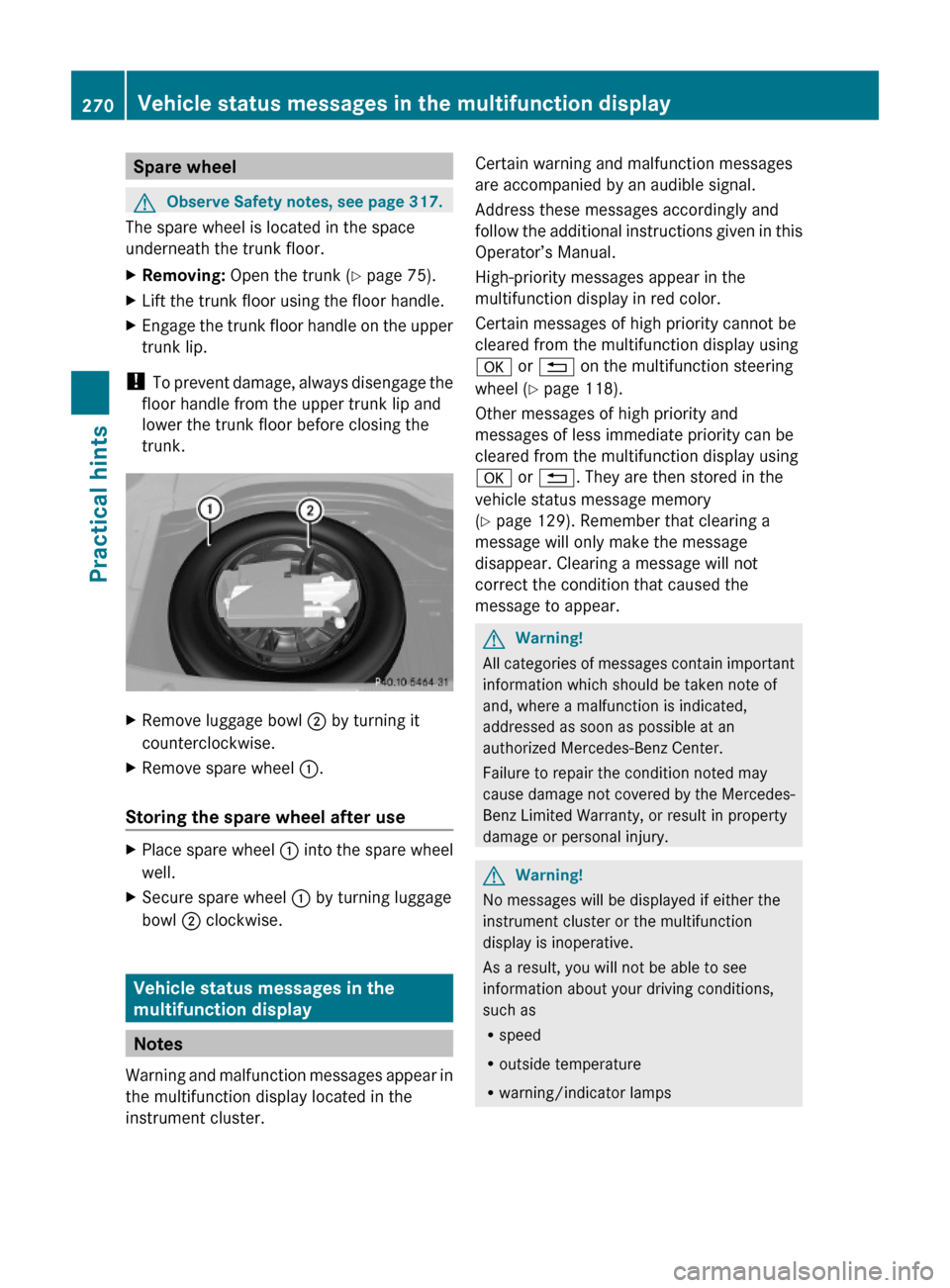
Spare wheelGObserve Safety notes, see page 317.
The spare wheel is located in the space
underneath the trunk floor.
XRemoving: Open the trunk (Y page 75).XLift the trunk floor using the floor handle.XEngage the trunk floor handle on the upper
trunk lip.
! To prevent damage, always disengage the
floor handle from the upper trunk lip and
lower the trunk floor before closing the
trunk.
XRemove luggage bowl ; by turning it
counterclockwise.
XRemove spare wheel :.
Storing the spare wheel after use
XPlace spare wheel : into the spare wheel
well.
XSecure spare wheel : by turning luggage
bowl ; clockwise.
Vehicle status messages in the
multifunction display
Notes
Warning and malfunction messages appear in
the multifunction display located in the
instrument cluster.
Certain warning and malfunction messages
are accompanied by an audible signal.
Address these messages accordingly and
follow the additional instructions given in this
Operator’s Manual.
High-priority messages appear in the
multifunction display in red color.
Certain messages of high priority cannot be
cleared from the multifunction display using
a or % on the multifunction steering
wheel (Y page 118).
Other messages of high priority and
messages of less immediate priority can be
cleared from the multifunction display using
a or %. They are then stored in the
vehicle status message memory
(Y page 129). Remember that clearing a
message will only make the message
disappear. Clearing a message will not
correct the condition that caused the
message to appear.
GWarning!
All categories of messages contain important
information which should be taken note of
and, where a malfunction is indicated,
addressed as soon as possible at an
authorized Mercedes-Benz Center.
Failure to repair the condition noted may
cause damage not covered by the Mercedes-
Benz Limited Warranty, or result in property
damage or personal injury.
GWarning!
No messages will be displayed if either the
instrument cluster or the multifunction
display is inoperative.
As a result, you will not be able to see
information about your driving conditions,
such as
Rspeed
Routside temperature
Rwarning/indicator lamps
270Vehicle status messages in the multifunction displayPractical hints
204_AKB; 5; 23, en-USd2ureepe,Version: 2.11.8.12009-07-16T17:54:06+02:00 - Seite 270
Page 279 of 364
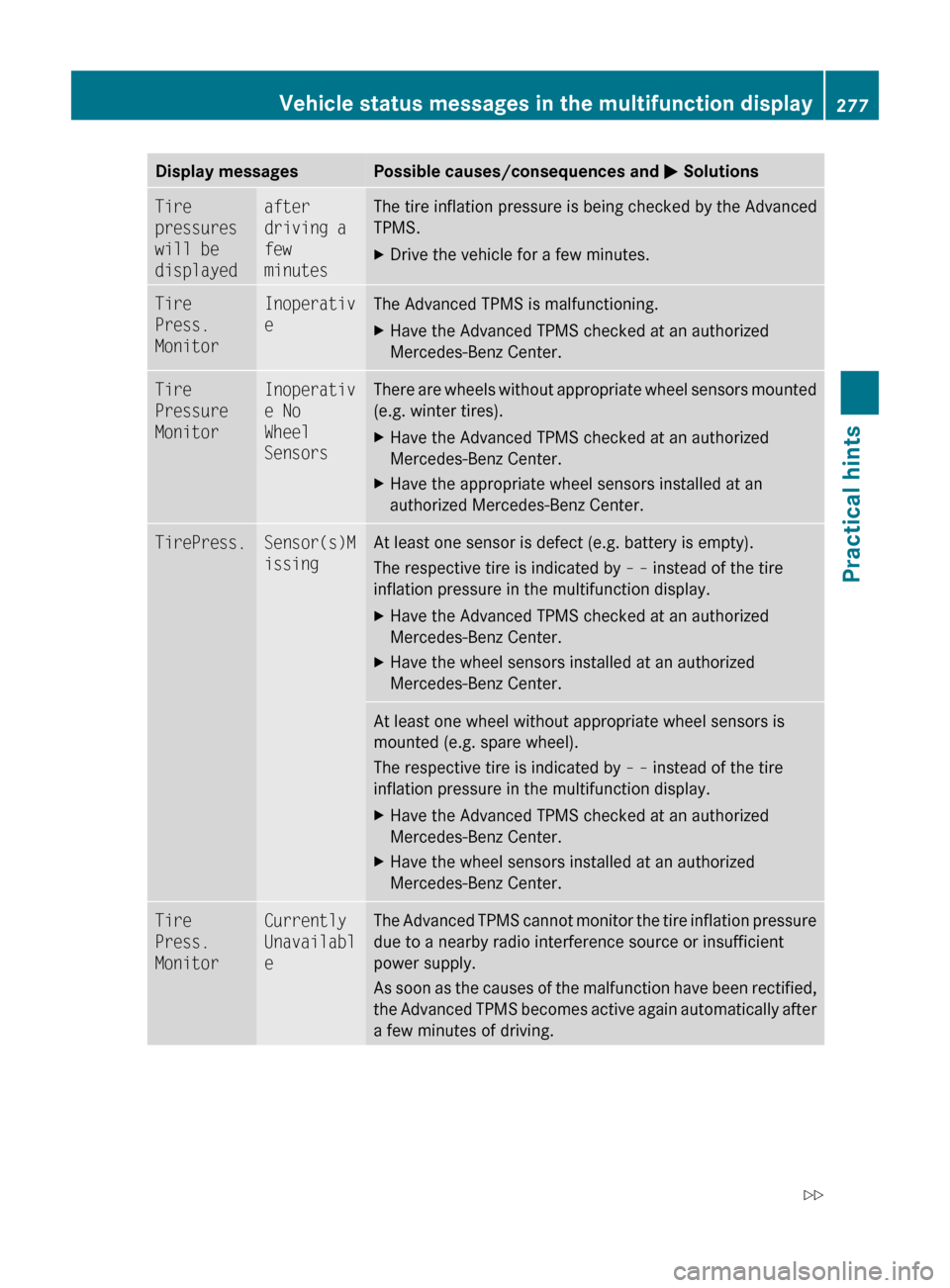
Display messagesPossible causes/consequences and M SolutionsTire
pressures
will be
displayedafter
driving a
few
minutesThe tire inflation pressure is being checked by the Advanced
TPMS.XDrive the vehicle for a few minutes.Tire
Press.
MonitorInoperativ
eThe Advanced TPMS is malfunctioning.XHave the Advanced TPMS checked at an authorized
Mercedes-Benz Center.Tire
Pressure
MonitorInoperativ
e No
Wheel
SensorsThere are wheels without appropriate wheel sensors mounted
(e.g. winter tires).XHave the Advanced TPMS checked at an authorized
Mercedes-Benz Center.XHave the appropriate wheel sensors installed at an
authorized Mercedes-Benz Center.TirePress.Sensor(s)M
issingAt least one sensor is defect (e.g. battery is empty).
The respective tire is indicated by – – instead of the tire
inflation pressure in the multifunction display.XHave the Advanced TPMS checked at an authorized
Mercedes-Benz Center.XHave the wheel sensors installed at an authorized
Mercedes-Benz Center.At least one wheel without appropriate wheel sensors is
mounted (e.g. spare wheel).
The respective tire is indicated by – – instead of the tire
inflation pressure in the multifunction display.XHave the Advanced TPMS checked at an authorized
Mercedes-Benz Center.XHave the wheel sensors installed at an authorized
Mercedes-Benz Center.Tire
Press.
MonitorCurrently
Unavailabl
eThe Advanced TPMS cannot monitor the tire inflation pressure
due to a nearby radio interference source or insufficient
power supply.
As soon as the causes of the malfunction have been rectified,
the Advanced TPMS becomes active again automatically after
a few minutes of driving.Vehicle status messages in the multifunction display277Practical hints204_AKB; 5; 23, en-USd2ureepe,Version: 2.11.8.12009-07-16T17:54:06+02:00 - Seite 277Z
Page 309 of 364
GWarning!
Each tire, including the spare (if provided),
should be checked at least once a month
when cold and inflated to the inflation
pressure recommended by the vehicle
manufacturer on the Tire and Loading
Information placard on the driver’s door B-
pillar or the tire inflation pressure label on the
inside of the fuel filler flap. If your vehicle has
tires of a different size than the size indicated
on the Tire and Loading Information placard
or the tire inflation pressure label, you should
determine the proper tire inflation pressure
for those tires.
As an added safety feature, your vehicle has
been equipped with a tire pressure monitoring
system (TPMS) that illuminates a low tire
pressure telltale when one or more of your
tires are significantly underinflated.
Accordingly, when the low tire pressure
telltale illuminates, you should stop and check
your tires as soon as possible, and inflate
them to the proper pressure. Driving on a
significantly underinflated tire causes the tire
to overheat and can lead to tire failure.
Underinflation also reduces fuel efficiency
and tire tread life, and may affect the vehicle’s
handling and stopping ability. Please note that
the TPMS is not a substitute for proper tire
maintenance, and it is the driver’s
responsibility to maintain correct tire
pressure, even if underinflation has not
reached the level to trigger illumination of the
TPMS low tire pressure telltale.
Your vehicle has also been equipped with a
TPMS malfunction indicator to indicate when
the system is not operating properly. The
TPMS malfunction indicator is combined with
the low tire pressure telltale. When the
system detects a malfunction, the telltale will
flash for approximately 1 minute and then
remain continuously illuminated. This
sequence will continue upon subsequent
vehicle start-ups as long as the malfunction
exists. When the malfunction indicator is
illuminated, the system may not be able to
detect or signal low tire pressure as intended.
TPMS malfunctions may occur for a variety of
reasons, including the installation of
incompatible replacement or alternate tires
or wheels on the vehicle that prevent the
TPMS from functioning properly. Always
check the TPMS malfunction telltale after
replacing one or more tires or wheels on your
vehicle to ensure that the replacement or
alternate tires and wheels allow the TPMS to
continue to function properly.
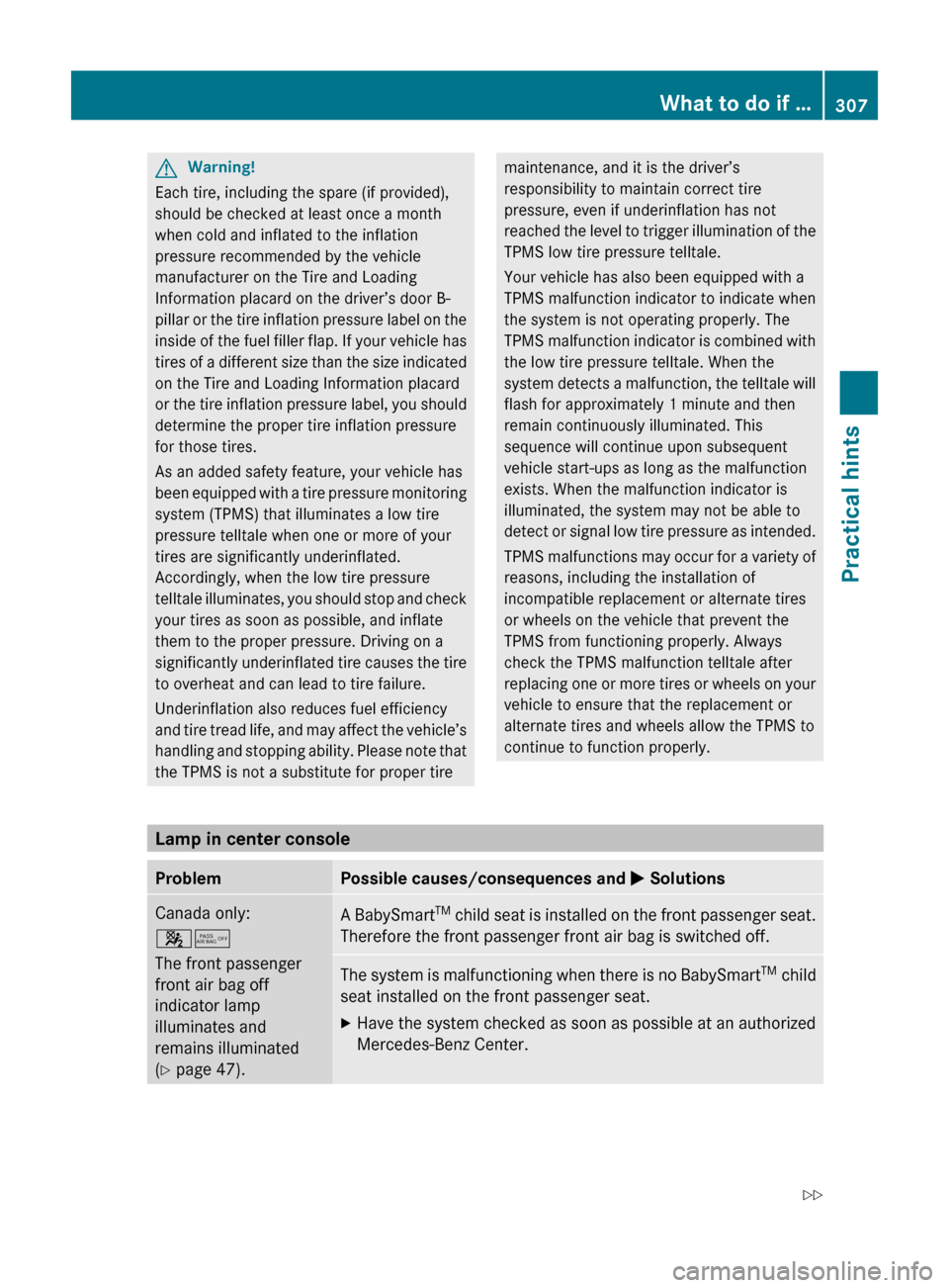
Lamp in center console
ProblemPossible causes/consequences and M SolutionsCanada only:
45
The front passenger
front air bag off
indicator lamp
illuminates and
remains illuminated
( Y page 47).A BabySmart TM
child seat is installed on the front passenger seat.
Therefore the front passenger front air bag is switched off.The system is malfunctioning when there is no BabySmart TM
child
seat installed on the front passenger seat.XHave the system checked as soon as possible at an authorized
Mercedes-Benz Center.What to do if …307Practical hints204_AKB; 5; 23, en-USd2ureepe,Version: 2.11.8.12009-07-16T17:54:06+02:00 - Seite 307Z