Page 201 of 285
The fuses are coded as follows.
Fuse/Relay
LocationFuse Amp
RatingProtected Circuits
1 10A Starter relay coil
2 10A Restraint control module (RCM),
Occupant classification sensor
(OCS), Passenger airbag
deactivation indicator (PADI)
3 10A Audio
4 10A Back-up lamps, Anti-lock brake
system (ABS)
5 7.5A Lighting control module (LCM)
6 10A Passive anti-theft system (PATS),
Powertrain control module (PCM)
relay coil, Ignition relay coil, Fuel
relay coil
7 10A Wiper module
Roadside Emergencies
201
2010 Town Car(tow)
Owners Guide, 1st Printing
USA(fus)
Page 202 of 285
Fuse/Relay
LocationFuse Amp
RatingProtected Circuits
8 10A Power decklid module (PDM),
Overdrive cancel switch, Cluster,
Compass module, LCM, Traction
Control™ switch
9 7.5A Door lock switch illumination,
Heated seat switch illumination,
Electrochromatic mirror
10 15A Hazards
11 15A Turn signal
12 15A Audio
13 10A Extended rear park aide module,
Cluster
14 15A Adjustable pedals, Delayed
accessory relay coil
15 10A Dual automatic temperature
control (DATC) module
16 20A OBD II
17 10A A/C cycle switch, Heated seat
modules
18 15A LCM (Interior lighting)
19 7.5A Driver’s door module (DDM)
switches, PDM, Power mirrors,
Driver seat module (DSM), DDM,
PAT S L E D
20 10A LCM (Right-hand low beam)
21 10A Analog clock, LCM (Illumination)
22 10A LCM (Left-hand low beam)
23 10A LCM
24 15A LCM (High beams), Multi-function
switch (Flash-to-pass)
25 10A DATC module, Cluster
Roadside Emergencies
202
2010 Town Car(tow)
Owners Guide, 1st Printing
USA(fus)
Page 205 of 285
Fuse/Relay
LocationFuse Amp
RatingProtected Circuits
13 10A* Rear air suspension module
(RASM)
14 20A* Stop lamp switch
15 15A* Lumbar, Fuel door
16 20A* Heated seats
17 – Not used
18 – Not used
19 15A* Injectors
20 15A* PCM
21 15A* Powertrain loads and sensors
22 — Not used
23 10A* Heated mirrors
24 – Not used
101 40A** Blower relay feed
102 50A** Cooling fan
103 50A** Instrument panel fuse box feed #1
104 50A** Instrument panel fuse box feed #2
105 30A** Starter relay feed
106 40A** ABS module (Pump)
107 40A** Rear defroster relay feed
108 40A** Power decklid module (PDM)
109 20A** ABS module (Valves)
110 30A** Wiper module
111 20A** Left rear power point
112 30A** RASM (Air compressor)
113 20A** Rear power point #2
114 20A** Instrument panel fuse box feed #3
115 20A** Rear cigar lighters
116 30A** Decklid pulldown module
117 20A** Cigar lighter
118 — Not used
Roadside Emergencies
205
2010 Town Car(tow)
Owners Guide, 1st Printing
USA(fus)
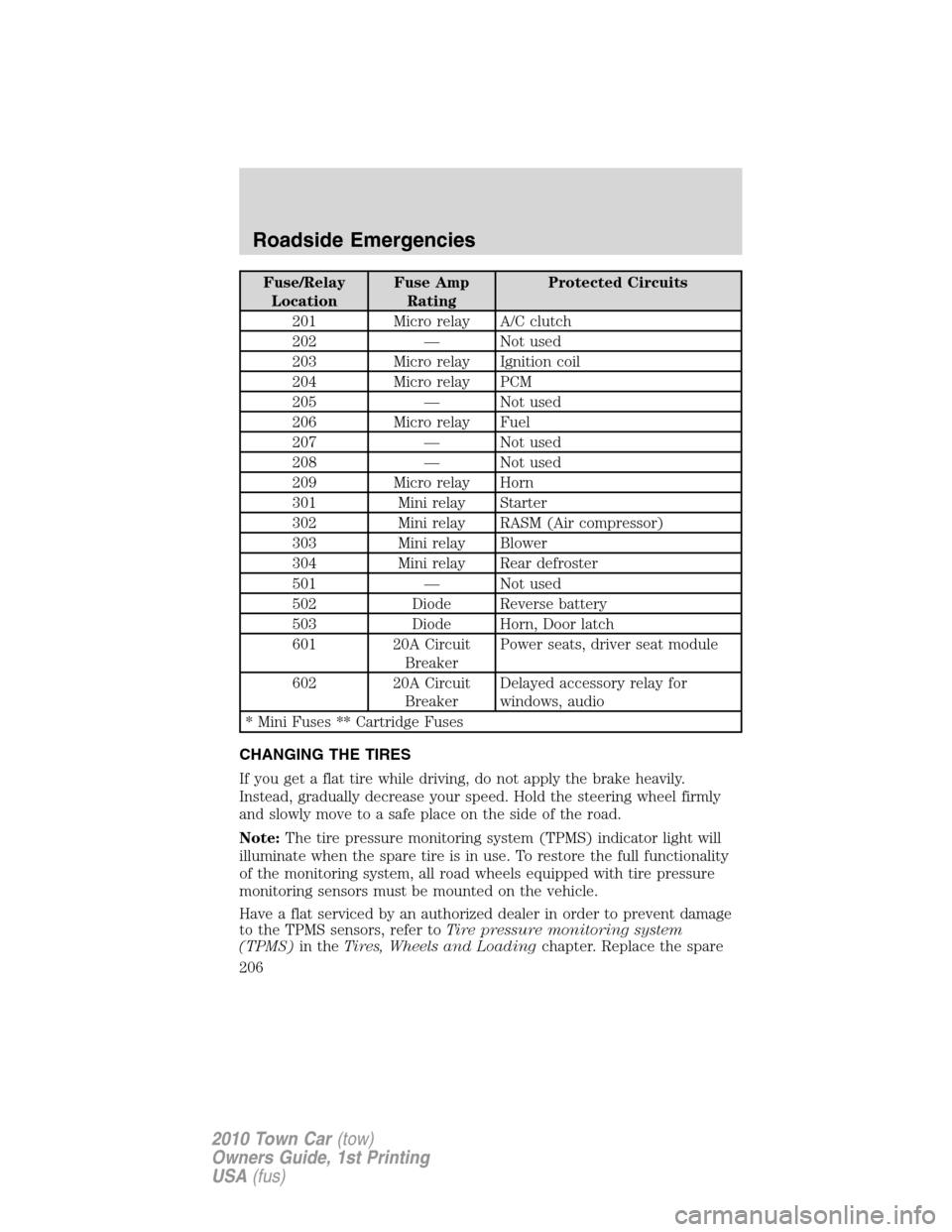
Page 206 of 285

Fuse/Relay
LocationFuse Amp
RatingProtected Circuits
201 Micro relay A/C clutch
202 — Not used
203 Micro relay Ignition coil
204 Micro relay PCM
205 — Not used
206 Micro relay Fuel
207 — Not used
208 — Not used
209 Micro relay Horn
301 Mini relay Starter
302 Mini relay RASM (Air compressor)
303 Mini relay Blower
304 Mini relay Rear defroster
501 — Not used
502 Diode Reverse battery
503 Diode Horn, Door latch
601 20A Circuit
BreakerPower seats, driver seat module
602 20A Circuit
BreakerDelayed accessory relay for
windows, audio
* Mini Fuses ** Cartridge Fuses
CHANGING THE TIRES
If you get a flat tire while driving, do not apply the brake heavily.
Instead, gradually decrease your speed. Hold the steering wheel firmly
and slowly move to a safe place on the side of the road.
Note:The tire pressure monitoring system (TPMS) indicator light will
illuminate when the spare tire is in use. To restore the full functionality
of the monitoring system, all road wheels equipped with tire pressure
monitoring sensors must be mounted on the vehicle.
Have a flat serviced by an authorized dealer in order to prevent damage
to the TPMS sensors, refer toTire pressure monitoring system
(TPMS)in theTires, Wheels and Loadingchapter. Replace the spare
Roadside Emergencies
206
2010 Town Car(tow)
Owners Guide, 1st Printing
USA(fus)
Page 209 of 285

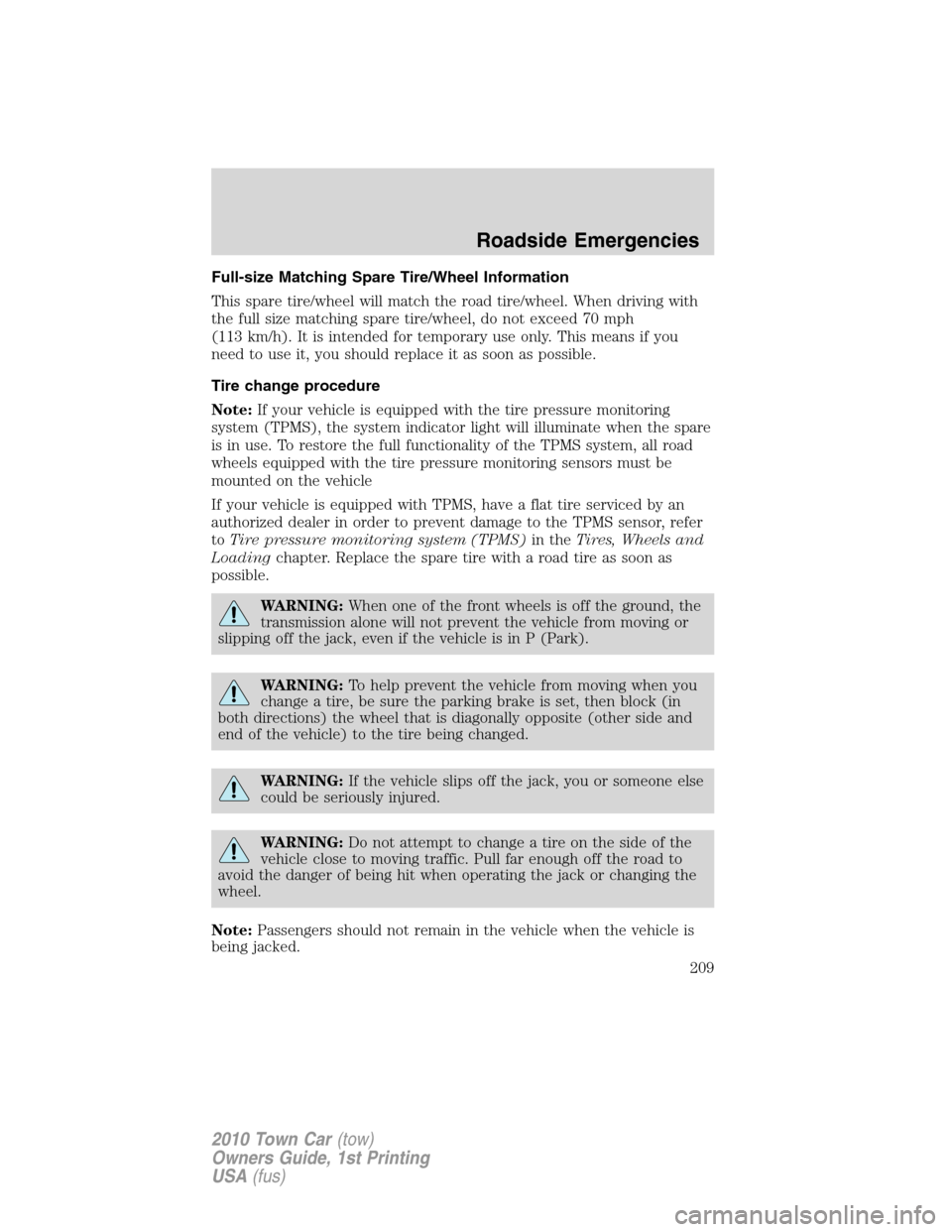
Full-size Matching Spare Tire/Wheel Information
This spare tire/wheel will match the road tire/wheel. When driving with
the full size matching spare tire/wheel, do not exceed 70 mph
(113 km/h). It is intended for temporary use only. This means if you
need to use it, you should replace it as soon as possible.
Tire change procedure
Note:If your vehicle is equipped with the tire pressure monitoring
system (TPMS), the system indicator light will illuminate when the spare
is in use. To restore the full functionality of the TPMS system, all road
wheels equipped with the tire pressure monitoring sensors must be
mounted on the vehicle
If your vehicle is equipped with TPMS, have a flat tire serviced by an
authorized dealer in order to prevent damage to the TPMS sensor, refer
toTire pressure monitoring system (TPMS)in theTires, Wheels and
Loadingchapter. Replace the spare tire with a road tire as soon as
possible.
WARNING:When one of the front wheels is off the ground, the
transmission alone will not prevent the vehicle from moving or
slipping off the jack, even if the vehicle is in P (Park).
WARNING:To help prevent the vehicle from moving when you
change a tire, be sure the parking brake is set, then block (in
both directions) the wheel that is diagonally opposite (other side and
end of the vehicle) to the tire being changed.
WARNING:If the vehicle slips off the jack, you or someone else
could be seriously injured.
WARNING:Do not attempt to change a tire on the side of the
vehicle close to moving traffic. Pull far enough off the road to
avoid the danger of being hit when operating the jack or changing the
wheel.
Note:Passengers should not remain in the vehicle when the vehicle is
being jacked.
Roadside Emergencies
209
2010 Town Car(tow)
Owners Guide, 1st Printing
USA(fus)
Page 216 of 285
Connecting the jumper cables
1. Connect the positive (+) jumper cable to the positive (+) terminal of
the discharged battery.
Note:In the illustrations,lightning boltsare used to designate the
assisting (boosting) battery.
2. Connect the other end of the positive (+) cable to the positive (+)
terminal of the assisting battery.
+–+–
+–+–
Roadside Emergencies
216
2010 Town Car(tow)
Owners Guide, 1st Printing
USA(fus)
Page 218 of 285
Jump starting
1. Start the engine of the booster vehicle and run the engine at
moderately increased speed.
2. Start the engine of the disabled vehicle.
3. Once the disabled vehicle has been started, run both engines for an
additional three minutes before disconnecting the jumper cables.
Removing the jumper cables
Remove the jumper cables in the reverse order that they were
connected.
1. Remove the jumper cable from thegroundmetal surface.
Note:In the illustrations,lightning boltsare used to designate the
assisting (boosting) battery.
2. Remove the jumper cable on the negative (-) connection of the
booster vehicle’s battery.
+–+–
+–+–
Roadside Emergencies
218
2010 Town Car(tow)
Owners Guide, 1st Printing
USA(fus)
Page 229 of 285

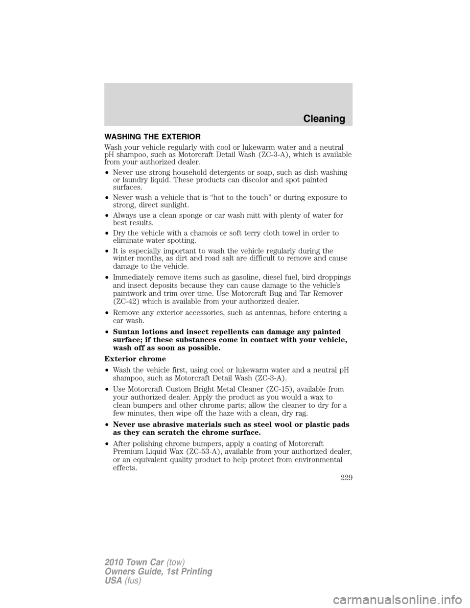
WASHING THE EXTERIOR
Wash your vehicle regularly with cool or lukewarm water and a neutral
pH shampoo, such as Motorcraft Detail Wash (ZC-3-A), which is available
from your authorized dealer.
•Never use strong household detergents or soap, such as dish washing
or laundry liquid. These products can discolor and spot painted
surfaces.
•Never wash a vehicle that is “hot to the touch” or during exposure to
strong, direct sunlight.
•Always use a clean sponge or car wash mitt with plenty of water for
best results.
•Dry the vehicle with a chamois or soft terry cloth towel in order to
eliminate water spotting.
•It is especially important to wash the vehicle regularly during the
winter months, as dirt and road salt are difficult to remove and cause
damage to the vehicle.
•Immediately remove items such as gasoline, diesel fuel, bird droppings
and insect deposits because they can cause damage to the vehicle’s
paintwork and trim over time. Use Motorcraft Bug and Tar Remover
(ZC-42) which is available from your authorized dealer.
•Remove any exterior accessories, such as antennas, before entering a
car wash.
•Suntan lotions and insect repellents can damage any painted
surface; if these substances come in contact with your vehicle,
wash off as soon as possible.
Exterior chrome
•Wash the vehicle first, using cool or lukewarm water and a neutral pH
shampoo, such as Motorcraft Detail Wash (ZC-3-A).
•Use Motorcraft Custom Bright Metal Cleaner (ZC-15), available from
your authorized dealer. Apply the product as you would a wax to
clean bumpers and other chrome parts; allow the cleaner to dry for a
few minutes, then wipe off the haze with a clean, dry rag.
•Never use abrasive materials such as steel wool or plastic pads
as they can scratch the chrome surface.
•After polishing chrome bumpers, apply a coating of Motorcraft
Premium Liquid Wax (ZC-53-A), available from your authorized dealer,
or an equivalent quality product to help protect from environmental
effects.
Cleaning
229
2010 Town Car(tow)
Owners Guide, 1st Printing
USA(fus)