2010 KIA Rio Page 7
[x] Cancel search: Page 7Page 39 of 236
Knowing your vehicle
30
3
Safety belt restraint system We strongly recommend that the driver
and all passengers be properly
restrained at all times by using the safety
belts provided with the vehicle. Proper
use of the safety belts decreases the risk
of severe injury or death in accidents or
sudden stops. In most states, and in
Canada, the law requires their use.
All seats have lap/shoulder belts. Inertial
locks in the safety belt retractors allow all
of the lap/shoulder safety belts to remain
unlocked during normal vehicle opera-
tion. This allows the occupants some
freedom of movement and increased
comfort while using the safety belts. If a
force is applied to the vehicle, such as a
strong stop, a sharp turn, or a collision,
the safety belt retractors will automatical-
ly lock the safety belts.
Since the inertial locks do not require a
collision in order to lock up, you may
become aware of the safety belts locking
while braking or going around sharp cor-
ners.
Always use the rear seat position(s) to
install your child restraint(s). The rear safety belts use a special auto-
lock feature designed to allow a child
restraint to be used in these positions
without an added locking clip. They nor-
mally lock only under extreme or emer-
gency conditions (emergency lock
mode). However they can be adjusted so
that they remain fixed and locked when a
child restraint system is placed in these
positions. (Use this auto-lock mode only
to secure a child restraint, never for pas-
sengers restrained by the safety belts.)
Page 3-42 gives instructions on placing
the safety belt in the auto lock mode.
The drivers safety belt can only operate
in the emergency lock mode.
WARNING- Safety belts
To minimize the risk of serious or
fatal injury in an accident, the driv-
er and all passengers should use
the appropriate safety restraints for
their age and size. The presence of
air bags does not change the need
to be properly restrained by a safe-
ty belt or size-appropriate child
restraint. In fact, air bags are
designed to work the best when
passengers are correctly restrained
in the vehicle.
Be sure you are familiar with the
information in this section,
including the information on
infant and child restraints.
Read the safety warnings on the sun visors of your vehicle also.
WARNING- Child restraint
in front seat
Never install a child restraint sys-
tem in the front passenger position,
as an inflating air bag could cause
serious or fatal injury to a child in
that position.
Page 72 of 236
363
Knowing your vehicle
Repairing or scrapping the vehicle
Repairing/replacing the steeringwheel, instrument panel, center con-
sole headliner/pillar trim, or modifying
vehicle sheet metal components could
disable the air bag system. Have such
repairs and maintenance performed by
an authorized Kia dealer.
Special care must be taken in scrap- ping or junking an air bag-equipped
vehicle. Always refer such activities to
a qualified professional.
WARNING- No mainte-
nance or repair
Do not work on the air bag sys-
tem’s components or wiring. This
could cause the air bags to inflate
inadvertently, possibly seriously
injuring someone. Working on the
system could also disable the
system so that the air bags would
not deploy in a collision.
Any work on the air bag system, such as removing, installing, or
repairing the steering wheel must
be performed by a qualified Kia
technician. Improper handling of
the air bag system including the
steering wheel may result in seri-
ous personal injury or death.
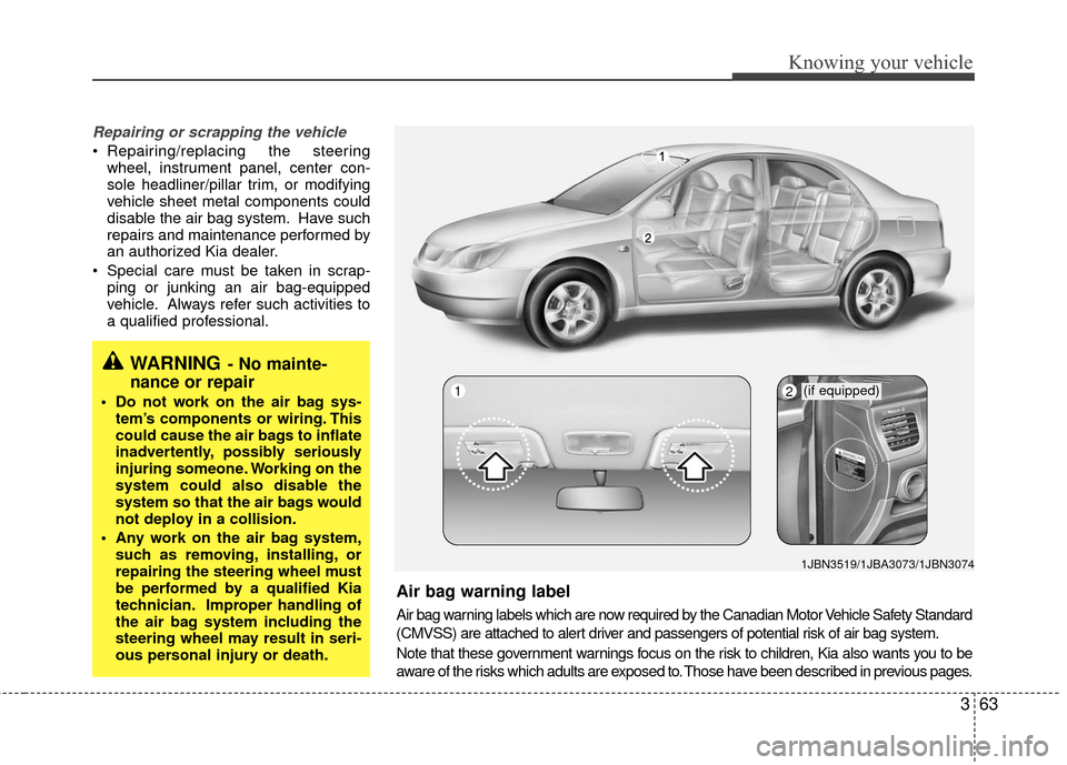
Air bag warning label
Air bag warning labels which are now required by the Canadian Motor Vehicle Safety Standard
(CMVSS) are attached to alert driver and passengers of potential risk of air bag system.
Note that these government warnings focus on the risk to children, Kia also wants you to be
aware of the risks which adults are exposed to. Those have been described in previous pages.
2(if equipped)
1JBN3519/1JBA3073/1JBN3074
1
Page 92 of 236
383
Knowing your vehicle
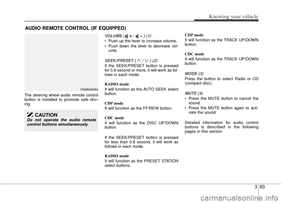
The steering wheel audio remote control
button is installed to promote safe driv-
ing.
VOLUME ( / ) (1)
Push up the lever to increase volume.
Push down the lever to decrease vol-ume.
SEEK/PRESET ( / ) (2)
If the SEEK/PRESET button is pressed
for 0.8 second or more, it will work as fol-
lows in each mode.
RADIO mode
It will function as the AUTO SEEK select
button.
CDP mode
It will function as the FF/REW button.
CDC mode
It will function as the DISC UP/DOWN
button.
If the SEEK/PRESET button is pressed
for less than 0.8 second, it will work as
follows in each mode.
RADIO mode
It will function as the PRESET STATION
select buttons. CDP mode
It will function as the TRACK UP/DOWN
button.
CDC mode
It will function as the TRACK UP/DOWN
button.
MODE (3)
Press the button to select Radio or CD
(compact disc).
MUTE (4)
Press the MUTE button to cancel the
sound.
Press the MUTE button again to acti- vate the sound.
Detailed information for audio control
buttons is described in the following
pages in this section.
AUDIO REMOTE CONTROL (IF EQUIPPED)
OAM049084
CAUTION
Do not operate the audio remote control buttons simultaneously.
Page 129 of 236
417
Driving your vehicle
Each of these actions will cancel cruise
control operation (the SET indicator light
in the instrument cluster will go off), but it
will not turn the system off. If you wish to
resume cruise control operation, push
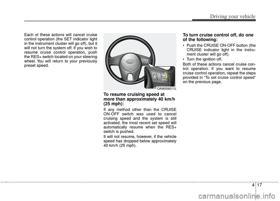
the RES+ switch located on your steering
wheel. You will return to your previously
preset speed.
To resume cruising speed at
more than approximately 40 km/h
(25 mph):
If any method other than the CRUISE
ON-OFF switch was used to cancel
cruising speed and the system is still
activated, the most recent set speed will
automatically resume when the RES+
switch is pushed.
It will not resume, however, if the vehicle
speed has dropped below approximately
40 km/h (25 mph).
To turn cruise control off, do one
of the following:
Push the CRUISE ON-OFF button (theCRUISE indicator light in the instru-
ment cluster will go off).
Turn the ignition off.
Both of these actions cancel cruise con-
trol operation. If you want to resume
cruise control operation, repeat the steps
provided in “To set cruise control speed”
on the previous page.
OAM059011L
Page 190 of 236
621
In case of an emergency
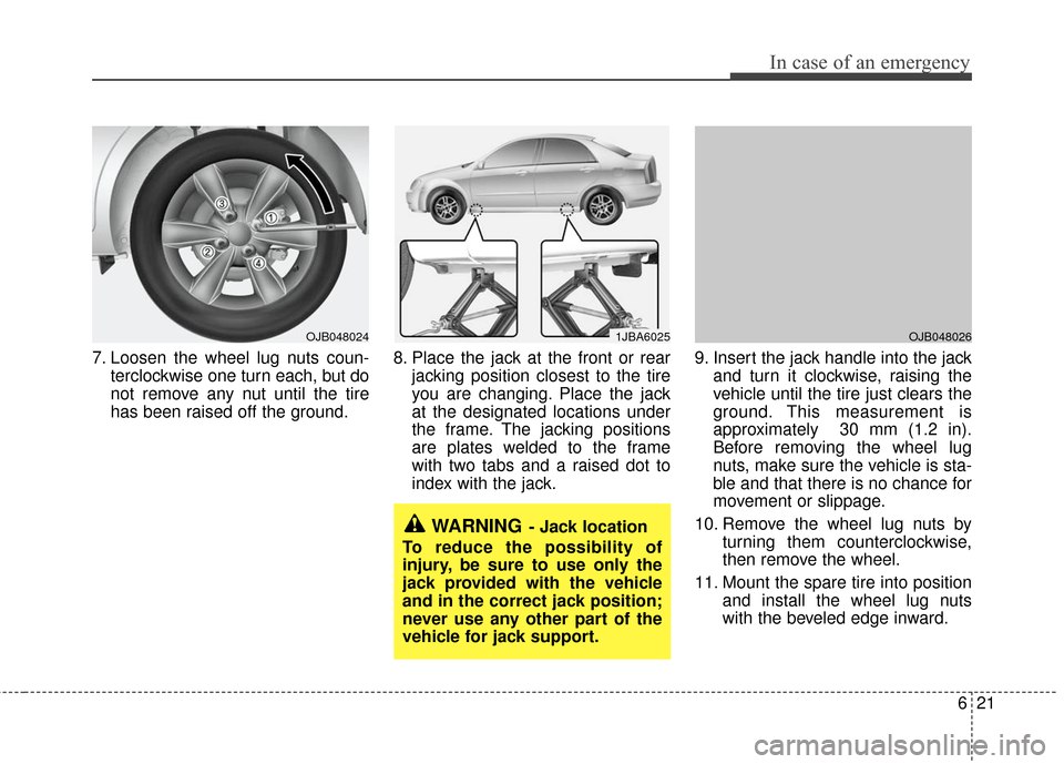
7. Loosen the wheel lug nuts coun-terclockwise one turn each, but do
not remove any nut until the tire
has been raised off the ground. 8. Place the jack at the front or rear
jacking position closest to the tire
you are changing. Place the jack
at the designated locations under
the frame. The jacking positions
are plates welded to the frame
with two tabs and a raised dot to
index with the jack. 9. Insert the jack handle into the jack
and turn it clockwise, raising the
vehicle until the tire just clears the
ground. This measurement is
approximately 30 mm (1.2 in).
Before removing the wheel lug
nuts, make sure the vehicle is sta-
ble and that there is no chance for
movement or slippage.
10. Remove the wheel lug nuts by turning them counterclockwise,
then remove the wheel.
11. Mount the spare tire into position and install the wheel lug nuts
with the beveled edge inward.
1JBA6025
WARNING- Jack location
To reduce the possibility of
injury, be sure to use only the
jack provided with the vehicle
and in the correct jack position;
never use any other part of the
vehicle for jack support.
OJB048026OJB048024
Page 193 of 236
Maintenance
27
MAINTENANCE SERVICES
You should exercise the utmost care to
prevent damage to your vehicle and
injury to yourself whenever performing
any maintenance or inspection proce-
dures.
Should you have any doubts concerning
the inspection or servicing of your vehi-
cle, we strongly recommend that you
have an authorized Kia dealer perform
this work.
An authorized Kia dealer has factory-
trained technicians and genuine Kia
parts to service your vehicle properly. For
expert advice and quality service, see an
authorized Kia dealer.
Inadequate, incomplete or insufficient
servicing may result in operational prob-
lems with your vehicle that could lead to
vehicle damage, an accident, or person-
al injury.Owner’s responsibility
Maintenance Service and Record
Retention are the owner's responsibil-
ity.
You should retain documents that show
proper maintenance has been performed
on your vehicle in accordance with the
scheduled maintenance service charts
shown on the following pages. You need
this information to establish your compli-
ance with the servicing and maintenance
requirements of your Kia warranties.
Detailed warranty information is provided
in your Warranty & Consumer Information
manual.
Repairs and adjustments required as a
result of improper maintenance or a lack
of required maintenance are not covered.
We strongly recommend that all vehicle
maintenance be performed by an author-
ized Kia dealer using genuine Kia parts.
Page 207 of 236

Maintenance
16
7
AUTOMATIC TRANSAXLE (IF EQUIPPED)
Checking the automatic transaxle
fluid level
The automatic transaxle fluid level
should be checked regularly.
Keep the vehicle on the level ground with
the parking brake applied and check the
fluid level according to the following pro-
cedure.
1. Place the selector lever in N (Neutral)
position and confirm the engine is run-
ning at normal idle speed.
2. After the transaxle is warmed up suffi- ciently (fluid temperature 158~176°F
(70~80°C)), for example by 10 minutes
usual driving, shift the selector lever
through all positions then place the
selector lever in N (Neutral) or P (Park)
position. 3. Confirm that the fluid level is in “HOT”
range on the level gauge. If the fluid
level is lower, add the specified fluid
from the fill hole. If the fluid level is
higher, drain the fluid from the drain
hole.
4. If the fluid level is checked in cold con- dition (fluid temperature 68~86°F
(20~30°C) add the fluid to “COLD” line
and then recheck the fluid level
according to the above step 2.
1JBA70061LDA5009
WARNING - Transaxle fluid
The transaxle fluid level should be
checked when the engine is at nor-
mal operating temperature. This
means that the engine, radiator,
radiator hose and exhaust system
etc., are very hot. Exercise great
care not to burn yourself during this
procedure.
WARNING- Parking brake
To avoid sudden movement of the
vehicle, apply parking brake and
depress the brake pedal before
moving the shift lever.
CAUTION
Low fluid level causes transaxle shift slippage. Overfilling cancause foaming, loss of fluid and transaxle malfunction.
The use of a non-specified fluid could result in transaxle malfunc-tion and failure.
Page 231 of 236

83
Specifications
Weights
Refer to the label describing GVWR & GAWR weights
attached to your vehicle.
(see page 5-10, Label information)
SizeGasoline Engine
Battery 12V / 55AH (20HR)
Generator 13.5V / 90A
Starter 12V-0.9kW
Gap 1.0 mm ~ 1.1 mm
Spec. BKR5ES-11, RC10YC4
Spark Plug
Engine
Electrical system
Item Gasoline Engine
BoreXStroke 76.5 mm X 87 mm (3.01 in X 3.43 in)
Displacement 1599 cc (97.6 cu.in)
Compression Ratio 10.0 ± 0.2