Page 209 of 522
INSTRUMENT CLUSTER DESCRIPTIONS
1. Fuel Gauge
The fuel gauge shows level of fuel in tank when ignition
switch is in the ON position.
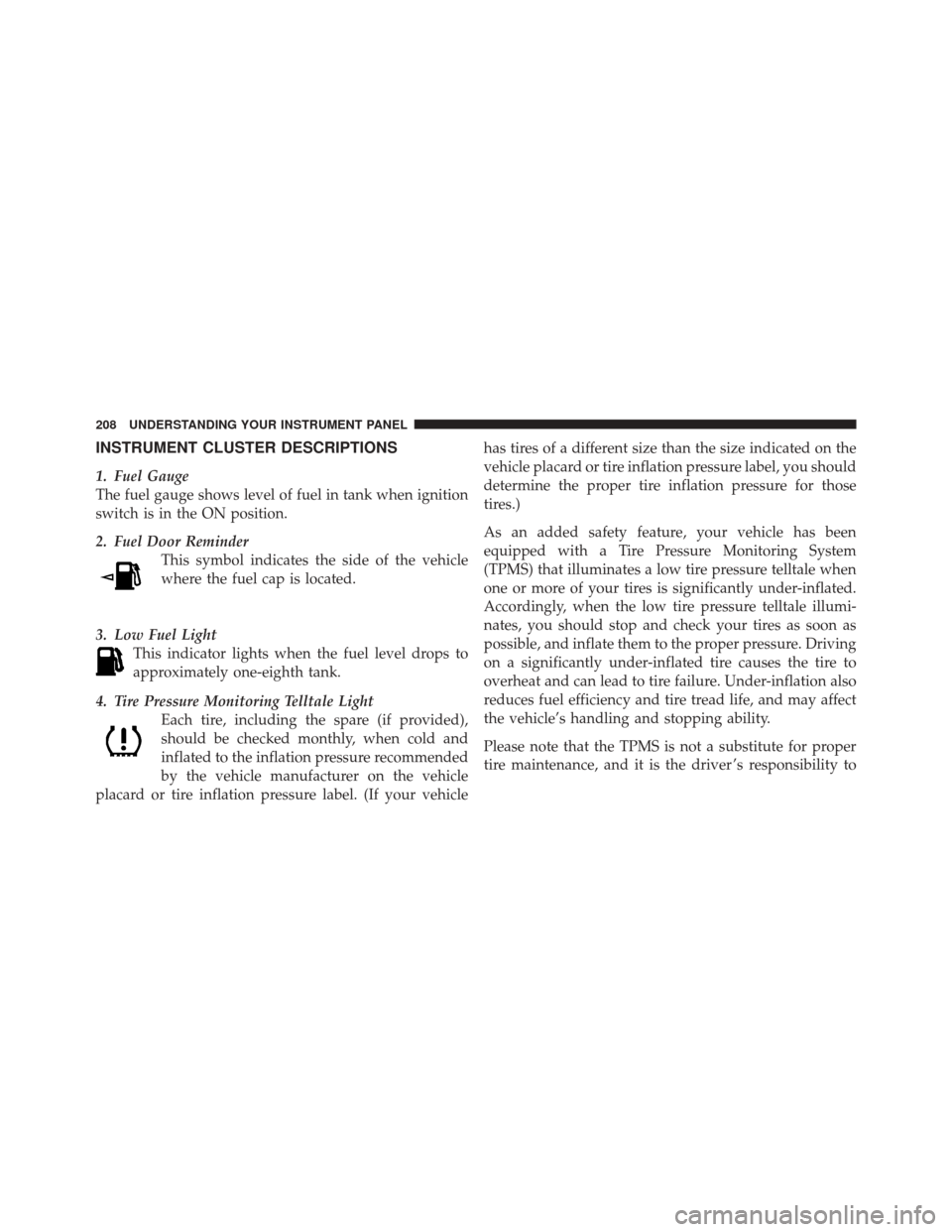
2. Fuel Door ReminderThis symbol indicates the side of the vehicle
where the fuel cap is located.
3. Low Fuel Light This indicator lights when the fuel level drops to
approximately one-eighth tank.
4. Tire Pressure Monitoring Telltale Light Each tire, including the spare (if provided),
should be checked monthly, when cold and
inflated to the inflation pressure recommended
by the vehicle manufacturer on the vehicle
placard or tire inflation pressure label. (If your vehicle has tires of a different size than the size indicated on the
vehicle placard or tire inflation pressure label, you should
determine the proper tire inflation pressure for those
tires.)
As an added safety feature, your vehicle has been
equipped with a Tire Pressure Monitoring System
(TPMS) that illuminates a low tire pressure telltale when
one or more of your tires is significantly under-inflated.
Accordingly, when the low tire pressure telltale illumi-
nates, you should stop and check your tires as soon as
possible, and inflate them to the proper pressure. Driving
on a significantly under-inflated tire causes the tire to
overheat and can lead to tire failure. Under-inflation also
reduces fuel efficiency and tire tread life, and may affect
the vehicle’s handling and stopping ability.
Please note that the TPMS is not a substitute for proper
tire maintenance, and it is the driver ’s responsibility to
208 UNDERSTANDING YOUR INSTRUMENT PANEL
Page 221 of 522

CHAngE OIL Message (Base And Mid Line Clusters
Only)
Your vehicle is equipped with an engine oil change
indicator system. The “CHANgE OIL” message will flash
in the instrument cluster odometer for approximately
12 seconds after a single chime has sounded to indicate
the next scheduled oil change interval. The engine oil
change indicator system is duty cycle based, which
means the engine oil change interval may fluctuate
dependent upon your personal driving style.
Unless reset, this message will continue to display each
time you turn the ignition switch to the ON position. To
turn off the message temporarily, press and release the
Trip Odometer button on the instrument cluster. To reset
the oil change indicator system (after performing the
scheduled maintenance) perform the following proce-
dure:1. Turn the ignition switch to the ON position.
Do not
start the engine.
2. Fully depress the accelerator pedal slowly three
times within 10 seconds.
3. Turn the ignition switch to the LOCK position.
NOTE: If the indicator message illuminates when you
start the vehicle, the oil change indicator system did not
reset. If necessary, repeat this procedure.
28. Cruise Indicator — If Equipped This indicator lights when the electronic speed
control system is turned on.
29. Shift Lever Indicator
The Shift Lever Indicator is self-contained within the
instrument cluster. It displays the gear position of the
automatic transmission.
220 UNDERSTANDING YOUR INSTRUMENT PANEL
Page 228 of 522
Unless reset, this message will continue to display each
time you turn the ignition switch to the ON position. To
turn off the message temporarily, press and release the
MENU button. To reset the oil change indicator system
(after performing the scheduled maintenance) perform
the following procedure:
1. Turn the ignition switch to the ON position.Do not
start the engine.
2. Fully depress the accelerator pedal slowly three times
within 10 seconds.
3. Turn the ignition switch to the LOCK position.
NOTE: If the indicator message illuminates when you
start the vehicle, the oil change indicator system did not
reset. If necessary, repeat this procedure.Trip Functions
Press and release the MENU button until one of the
following Trip Functions displays in the EVIC:
•Average Fuel Economy
•Distance To Empty
•Elapsed Time
•Display Units of Measure in
Press the SCROLL button to cycle through all the Trip
Computer functions.
The Trip Functions mode displays the following information:
•Average Fuel Economy
Shows the average fuel economy since the last reset. When
the fuel economy is reset, the display will read “RESET” or
show dashes for two seconds. Then, the history informa-
tion will be erased, and the averaging will continue from
the last fuel average reading before the reset.
4
UNDERSTANDING YOUR INSTRUMENT PANEL 227
Page 281 of 522
•Press the button in the center of the switch to change
modes (i.e., AM, FM, etc.).
Left-Hand Switch Functions for Radio Operation
•
Press the top of the switch to SEEK the next listenable
station up from the current setting.
•Press the bottom of the switch to SEEK the next
listenable station down from the current setting.
•Press the button in the center of the switch to tune to
the next preset that you have programmed.
Left-Hand Switch Functions for Media (i.e., CD)
Operation
•
Press the top of the switch once to listen to the next
track.
•Press the bottom of the switch once either to listen to
the beginning of the current track or to listen to thebeginning of the previous track if it is within one
second after the current track begins to play.
•Press the switch up or down twice to listen to the
second track, three times to listen to the third track,
and so forth.
•Press the button located in the center of the switch to
change to the next preset that you have programmed.
CD/DVD MAINTENANCE
To keep a CD/DVD in good condition, take the following
precautions:
1. Handle the disc by its edge; avoid touching the
surface.
2. If the disc is stained, clean the surface with a soft cloth,
wiping from center to edge.
3. Do not apply paper or tape to the disc; avoid scratch-
ing the disc.
280 UNDERSTANDING YOUR INSTRUMENT PANEL
Page 292 of 522
•Extended use of recirculation may cause the windows
to fog. If the interior of the windows begins to fog,
press the Recirculation button to return to outside air.
Some temp/humidity conditions will cause captured
interior air to condense on windows and hamper
visibility. For this reason, the system will not allow
Recirculation to be selected while in floor, defrost, or
defrost/floor mode. Attempting to use the recircula-
tion while in these modes will cause the LED in the
control button to blink and then turn off.
•Most of the time, when in Automatic Operation, you
can temporarily put the system into Recirculation
Mode by pressing the Recirculation button. However,
under certain conditions, while in Automatic Mode,
the system is blowing air out the defrost vents. When
these conditions are present, and the Recirculation
button is pressed, the indicator will flash and then turn
off. This tells you that you are unable to go into
Recirculation Mode at this time. If you would like thesystem to go into Recirculation Mode, you must first
move the Mode knob to Panel, Panel/Floor and then
press the Recirculation button. This feature reduces the
possibility of window fogging.
Operating Tips
NOTE:
Refer to the chart at the end of this section for
suggested control settings for various weather condi-
tions.
Summer Operation
The engine cooling system in air-conditioned vehicles
must be protected with a high-quality antifreeze coolant
to provide proper corrosion protection and to protect
against engine overheating. A solution of 50% ethylene
glycol antifreeze coolant and 50% water is recommended.
Refer to “Maintenance Procedures” in Section 7 of this
manual for proper coolant selection.
4
UNDERSTANDING YOUR INSTRUMENT PANEL 291
Page 294 of 522
Outside Air Intake
Make sure the air intake, located directly in front of the
windshield, is free of obstructions such as leaves. Leaves
collected in the air intake may reduce airflow, and if they
enter the plenum, they could plug the water drains. In
winter months, make sure the air intake is clear of ice,
slush, and snow.
A/C Air Filter — If Equipped
The A/C Filter prevents most dust and pollen from
entering the cabin. The filter acts on air coming from
outside the vehicle and recirculated air within the pas-
senger compartment. Refer to “Maintenance Procedures”
in Section 7 of this manual for A/C Air Filter service
information or see your authorized dealer for service.
Refer to the “Maintenance Schedules” in Section 8 of this
manual for filter service intervals.
4
UNDERSTANDING YOUR INSTRUMENT PANEL 293
Page 324 of 522
Maintenance
After driving through deep water, inspect your vehicle
fluids and lubricants (engine, transmission, axle, transfer
case) to assure they have not been contaminated. Con-
taminated fluids and lubricants (milky, foamy in appear-
ance) should be flushed/changed as soon as possible to
prevent component damage.
Driving In Snow, Mud and Sand
In heavy snow, when pulling a load, or for additional
control at slower speeds, shift the transmission to a low
gear and shift the transfer case to 4WD LOW if necessary.
Refer to “Four-Wheel Drive Operation” in this section.
Do not shift to a lower gear than necessary to maintain
headway. Over-revving the engine can spin the wheels
and traction will be lost.
Avoid abrupt downshifts on icy or slippery roads be-
cause engine braking may cause skidding and loss of
control.
Hill Climbing
NOTE:Before attempting to climb a hill, determine the
conditions at the crest and/or on the other side.
Before climbing a steep hill, shift the transmission to a
lower gear and shift the transfer case to 4WD LOW. Use
first gear and 4WD LOW for very steep hills.
If you stall or begin to lose headway while climbing a
steep hill, allow your vehicle to come to a stop and
immediately apply the brakes. Restart the engine and
shift to REVERSE. Back slowly down the hill allowing the
compression braking of the engine to help regulate your
speed. If the brakes are required to control vehicle speed,
apply them lightly and avoid locking or skidding the
tires.
5
STARTING AND OPERATING 323
Page 363 of 522
The suggested rotation method is the “forward-cross”
shown in the following diagram.
These effects can be reduced by timely rotation of tires.
The benefits of rotation are especially worthwhile with
aggressive tread designs such as those on On/Off Roadtype tires. Rotation will increase tread life, help to main-
tain mud, snow, and wet traction levels, and contribute to
a smooth, quiet ride.
CAUTION!
Proper operation of four-wheel drive vehicles de-
pends on tires of equal size, type and circumference
on each wheel. Any difference in tire size can cause
damage to the transfer case. Tire rotation schedule
should be followed to balance tire wear.
Refer to the “Maintenance Schedule” in Section 8 for the
proper maintenance intervals. Remember, more frequent
rotation is permissible if desired. Also, correct for any-
thing causing rapid or unusual wear prior to performing
the tire rotation.
Tire Rotation
362 STARTING AND OPERATING