2010 JEEP GRAND CHEROKEE phone
[x] Cancel search: phonePage 3 of 84

INTRODUCTION/WELCOME
WELCOME FROM
CHRYSLER GROUP LLC.......... 2
CONTROLS AT A GLANCE
DRIVER COCKPIT.............. 4
INSTRUMENT CLUSTER .......... 6
GETTING STARTED
KEYFOB .................. 8
THEFT ALARM............... 9
SEAT BELT ................. 9
CHILD RESTRAINTS ............10
FRONT SEATS ...............11
REAR SEATS ................14
TILT / TELESCOPING STEERING
COLUMN ..................15
ADJUSTABLE PEDALS ...........16
PROGRAMMABLE FEATURES .......17
OPERATING YOUR VEHICLE
TURN SIGNAL/LIGHTS LEVER .......18
WIPER/WASHER LEVER ..........19
SPEED CONTROL LEVER .........20
ELECTRONIC RANGE SELECTION (ERS) . 21
MANUAL CLIMATE CONTROLS ......22
AUTOMATIC TEMPERATURE
CONTROLS (ATC) ..............22
PARKSENSE
®REAR PARK ASSIST ....23
PARKVIEW®REAR BACK-UP CAMERA . . 23
LIFTGATE FLIPPER GLASS ........23
POWER SUNROOF .............24
WIND BUFFETING .............25
ELECTRONICS
NON-TOUCH-SCREEN RADIOS ......26
TOUCH-SCREEN RADIOS .........28
REMOTE AUDIO CONTROLS ........32
ELECTRONIC VEHICLE INFORMATION
CENTER (EVIC) ...............33
UNIVERSAL GARAGE DOOR OPENER . . . 33
POWER INVERTER .............35
POWER OUTLET ..............35
UCONNECT™ PHONE ...........36
VOICE COMMAND .............38
OFF-ROAD CAPABILITIES
FOUR-WHEEL DRIVE OPERATION .....39
UTILITY
INTERIOR STORAGE COMPARTMENTS . . 41
TRAILER TOWING WEIGHTS (MAXIMUM
TRAILER WEIGHT RATINGS)........42
RECREATIONAL TOWING (BEHIND
MOTORHOME, ETC.) ............43
BRAKE/TRANSMISSION INTERLOCK
MANUAL OVERRIDE ............44
WHAT TO DO IN EMERGENCIES
24 HOUR TOWING ASSISTANCE -
U.S. ONLY..................45
INSTRUMENT CLUSTER WARNING
LIGHTS ...................45
IF YOUR ENGINE OVERHEATS .......47
JACKING AND TIRE CHANGING ......48
JUMP-STARTING ..............53
EMERGENCY TOW HOOKS .........55
TOWING A DISABLED VEHICLE ......57
EVENT DATA RECORDER (EDR) ......58
MAINTAINING YOUR VEHICLE
OPENING THE HOOD............59
ENGINE COMPARTMENT .........60
FLUIDS AND CAPACITIES .........63
MAINTENANCE CHART ..........66
FUSES ...................68
TIRE PRESSURES .............73
WHEEL AND WHEEL TRIM CARE .....74
EXTERIOR BULBS .............74
CONSUMER ASSISTANCE
CHRYSLER GROUP LLC CUSTOMER
CENTER...................75
CHRYSLER CANADA INC. CUSTOMER
CENTER ...................75
ASSISTANCE FOR THE HEARING
IMPAIRED ..................75
PUBLICATIONS ORDERING ........75
REPORTING SAFETY DEFECTS IN
THE 50 UNITED STATES AND
WASHINGTON, D.C. ............76
TIRE WARRANTY ..............76
MOPAR ACCESSORIES
MOPAR®ACCESSORIES..........79
TABLE OF CONTENTS
Page 29 of 84
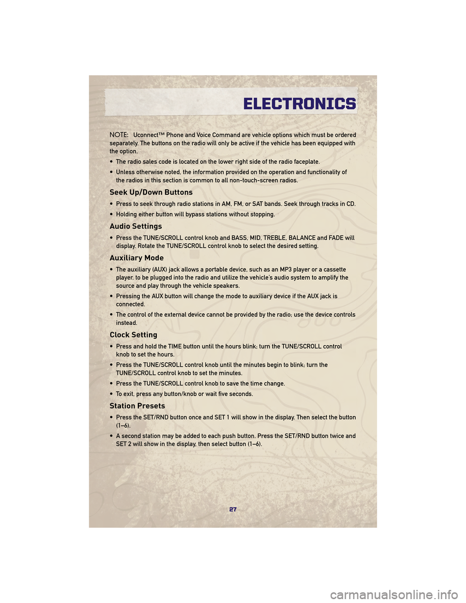
NOTE:Uconnect™ Phone and Voice Command are vehicle options which must be ordered
separately. The buttons on the radio will only be active if the vehicle has been equipped with
the option.
• The radio sales code is located on the lower right side of the radio faceplate.
• Unless otherwise noted, the information provided on the operation and functionality of the radios in this section is common to all non-touch-screen radios.
Seek Up/Down Buttons
• Press to seek through radio stations in AM, FM, or SAT bands. Seek through tracks in CD.
• Holding either button will bypass stations without stopping.
Audio Settings
• Press the TUNE/SCROLL control knob and BASS, MID, TREBLE, BALANCE and FADE willdisplay. Rotate the TUNE/SCROLL control knob to select the desired setting.
Auxiliary Mode
• The auxiliary (AUX) jack allows a portable device, such as an MP3 player or a cassetteplayer, to be plugged into the radio and utilize the vehicle’s audio system to amplify the
source and play through the vehicle speakers.
• Pressing the AUX button will change the mode to auxiliary device if the AUX jack is connected.
• The control of the external device cannot be provided by the radio; use the device controls instead.
Clock Setting
• Press and hold the TIME button until the hours blink; turn the TUNE/SCROLL controlknob to set the hours.
• Press the TUNE/SCROLL control knob until the minutes begin to blink; turn the TUNE/SCROLL control knob to set the minutes.
• Press the TUNE/SCROLL control knob to save the time change.
• To exit, press any button/knob or wait five seconds.
Station Presets
• Press the SET/RND button once and SET 1 will show in the display. Then select the button (1–6).
• A second station may be added to each push button. Press the SET/RND button twice and SET 2 will show in the display, then select button (1–6).
27
ELECTRONICS
Page 31 of 84
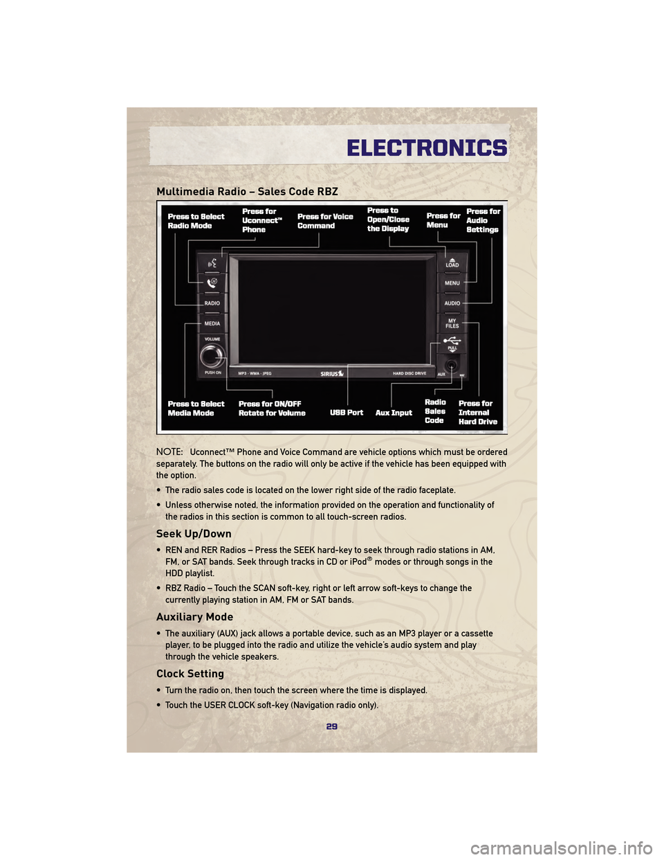
Multimedia Radio – Sales Code RBZ
NOTE:Uconnect™ Phone and Voice Command are vehicle options which must be ordered
separately. The buttons on the radio will only be active if the vehicle has been equipped with
the option.
• The radio sales code is located on the lower right side of the radio faceplate.
• Unless otherwise noted, the information provided on the operation and functionality of the radios in this section is common to all touch-screen radios.
Seek Up/Down
• REN and RER Radios – Press the SEEK hard-key to seek through radio stations in AM,FM, or SAT bands. Seek through tracks in CD or iPod®modes or through songs in the
HDD playlist.
• RBZ Radio – Touch the SCAN soft-key, right or left arrow soft-keys to change the currently playing station in AM, FM or SAT bands.
Auxiliary Mode
• The auxiliary (AUX) jack allows a portable device, such as an MP3 player or a cassetteplayer, to be plugged into the radio and utilize the vehicle’s audio system and play
through the vehicle speakers.
Clock Setting
• Turn the radio on, then touch the screen where the time is displayed.
• Touch the USER CLOCK soft-key (Navigation radio only).
29
ELECTRONICS
Page 37 of 84
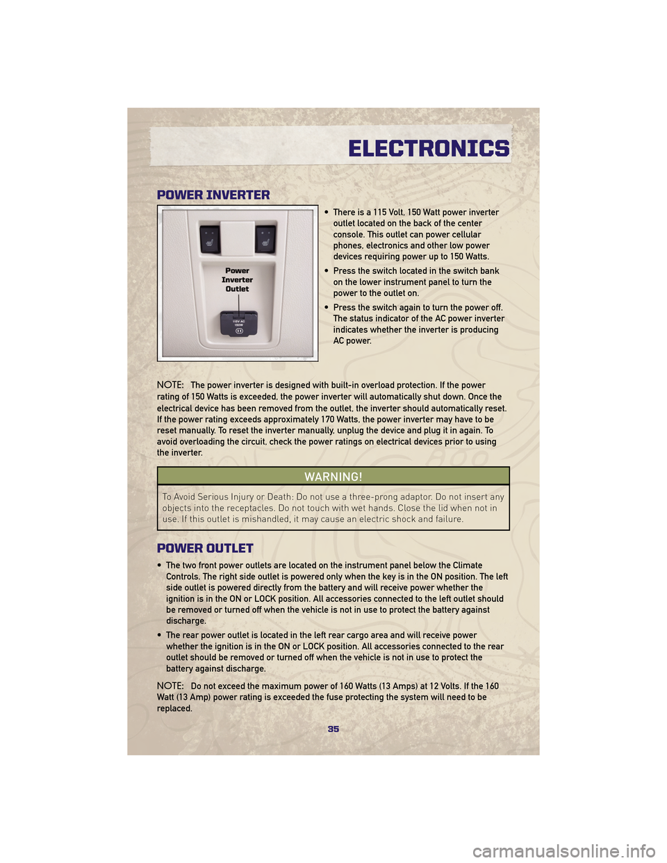
POWER INVERTER
• There is a 115 Volt, 150 Watt power inverteroutlet located on the back of the center
console. This outlet can power cellular
phones, electronics and other low power
devices requiring power up to 150 Watts.
• Press the switch located in the switch bank on the lower instrument panel to turn the
power to the outlet on.
• Press the switch again to turn the power off. The status indicator of the AC power inverter
indicates whether the inverter is producing
AC power.
NOTE: The power inverter is designed with built-in overload protection. If the power
rating of 150 Watts is exceeded, the power inverter will automatically shut down. Once the
electrical device has been removed from the outlet, the inverter should automatically reset.
If the power rating exceeds approximately 170 Watts, the power inverter may have to be
reset manually. To reset the inverter manually, unplug the device and plug it in again. To
avoid overloading the circuit, check the power ratings on electrical devices prior to using
the inverter.
WARNING!
To Avoid Serious Injury or Death: Do not use a three-prong adaptor. Do not insert any
objects into the receptacles. Do not touch with wet hands. Close the lid when not in
use. If this outlet is mishandled, it may cause an electric shock and failure.
POWER OUTLET
• The two front power outlets are located on the instrument panel below the Climate Controls. The right side outlet is powered only when the key is in the ON position. The left
side outlet is powered directly from the battery and will receive power whether the
ignition is in the ON or LOCK position. All accessories connected to the left outlet should
be removed or turned off when the vehicle is not in use to protect the battery against
discharge.
• The rear power outlet is located in the left rear cargo area and will receive power whether the ignition is in the ON or LOCK position. All accessories connected to the rear
outlet should be removed or turned off when the vehicle is not in use to protect the
battery against discharge.
NOTE: Do not exceed the maximum power of 160 Watts (13 Amps) at 12 Volts. If the 160
Watt (13 Amp) power rating is exceeded the fuse protecting the system will need to be
replaced.
35
ELECTRONICS
Page 38 of 84
Uconnect™ Phone
• The Uconnect™ Phone is a voice-activated, hands-free, in-vehicle communicationssystem.
• The Uconnect™ Phone allows you to dial a phone number with your cellular phone using simple voice commands.
• For vehicles equipped with Video Entertainment System (VES)™, refer to the Uconnect™ Phone section of the Uconnect™ User's Manual on the DVD for further details.
• For vehicles not equipped with VES™, refer to your vehicle Owner's Manual on the DVD for further details.
WARNING!
• Any voice commanded system should be used only in safe driving conditions following local laws and phone use. All attention should be kept on the roadway
ahead. Failure to do so may result in an accident causing serious injury or death.
• Your phone must be turned on and paired to the Uconnect™ Phone to allow use of this vehicle feature in emergency situations, when the cellular phone has network
coverage and stays paired to the Uconnect™ Phone.
NOTE: The Uconnect™ Phone requires a cellular phone equipped with the Bluetooth
®
Hands-Free Profile, Version 0.96 or higher. For Uconnect™ customer support, call
1–877–855–8400.
Phone Pairing
NOTE:Pairing is a one-time initial setup before using the phone. You will also need to
follow the Bluetooth®instructions in your cell phone user guide to complete the phone
pairing setup.
• Press the Phone button
to begin.
• Wait for the “ready” prompt and beep.
• (After the BEEP), say “Uconnect setup”.
• (After the BEEP), say “phone pairing”.
• (After the BEEP), say “pair a phone”.
• Follow the audible prompts.
• You will be asked to create a four-digit PIN which you will later need to enter into your phone (typically...settings, Bluetooth
®, device, list, new).
• You will then be prompted to give the phone pairing a name (each phone paired should have a unique name).
• Next you will be asked to give this new pairing a priority of 1 thru 7 (up to seven phones may be paired).
ELECTRONICS
36
Page 39 of 84
Making A Phone Call
• Press the Phone button.
• (After the BEEP), say “dial” (or “call” to a name).
• (After the BEEP), say number (or name).
Phonebook (Uconnect™ local) Edit
• Press the Phone button.
• (After the BEEP), say “phonebook”.
• (After the BEEP), say “new entry” or “list names” or “delete”.
• Follow the prompts.
Receiving A Call – Accept (And End)
• When an incoming call rings/is announced on Uconnect™, press the Phone button.
• To end a call, press the Phone button
.
Mute (Or Unmute) Microphone During Call
• During a call, press the Voice Command button.
• (After the BEEP), say “mute on” (or “mute off”).
Transfer Ongoing Call Between Handset And Vehicle
• During a call, press the Voice Command button.
• (After the BEEP), say “transfer call”.
Changing The Volume
• Start a dialogue by pressing the Phone button, then adjust the volume during a
normal call.
• Use the radio ON/OFF VOLUME rotary knob to adjust the volume to a comfortable level while the Uconnect™ system is speaking. Please note the volume setting for Uconnect™
is different than the audio system.
NOTE: To access the tutorial, press the Uconnect™ hard-key. After the BEEP, say
“tutorial”. Press any hard-key or touch the display to cancel the tutorial.
37
ELECTRONICS
Page 47 of 84

24 HOUR TOWING ASSISTANCE - U.S. ONLY
• Dial toll-free 1-800-521-2779.
• Provide your name, vehicle identification number and license plate number.
• Provide your location, including telephone number, from which you are calling.
• Briefly describe the nature of the problem and answer a few simple questions.
• You will be given the name of the service provider and an estimated time of arrival. If youfeel you are in an “unsafe situation”, please let us know. With your consent, we will
contact local police or safety authorities.
INSTRUMENT CLUSTER WARNING LIGHTS
- Electronic Stability Program (ESP) Indicator Light
• If this indicator light flashes during acceleration, apply as little throttle as possible. Whiledriving, ease up on the accelerator. Adapt your speed and driving to the prevailing road
conditions. To improve the vehicle's traction when starting off in deep snow, sand or
gravel, it may be desirable to switch the ESP system off.
- Tire Pressure Monitoring System (TPMS) Light
• A Tire Pressure Monitoring Light and a “low tire” message will display in your instrumentcluster along with an audible chime if one or more of your vehicle’s four road tires are
significantly under-inflated.
• Check the inflation pressure of each tire and inflate to the recommended pressure for your vehicle. The tire pressures recommended for your vehicle are found on the “Tire and
Loading Information” label located on the driver’s side door opening. The TPMS light
should not be used as a tire pressure gauge when adjusting your tire pressure.
• It is recommended that you check the tire pressure in the morning when tires are cool; inflate each tire to the recommended pressure for your vehicle. The light will turn off
after your vehicle’s tire pressures are properly inflated and the pressure has been
recognized. The vehicle may need to be driven for up to 20 minutes above 15 mph
(25 km/h) before the light will turn off.
• Temperature changes can affect tire pressure, causing the TPMS light to turn on. Tire pressures will also increase as the vehicle is driven – this is normal and you should not
adjust for this increased pressure.
• Driving on under-inflated tires reduces your vehicle’s fuel efficiency and tire tread life. If a spare tire is in use on the vehicle, the TPMS light may turn on.
- Brake Warning Light
• The Brake Warning light illuminates when there is either a system malfunction or theparking brake is applied. If the light is on and the parking brake is not applied, it
indicates a possible brake hydraulic malfunction, brake booster problem or an Anti-Lock
Brake System problem.
• We recommend you drive to the nearest Service Center and have the vehicle serviced immediately.
45
WHAT TO DO IN EMERGENCIES
Page 57 of 84

WARNING!
Do not connect the cable to the negative post(-)of the discharged battery. The
resulting electrical spark could cause the battery to explode and could result in
personal injury.
• Start the engine in the vehicle that has the booster battery, let the engine idle a few minutes, and then start the engine in the vehicle with the discharged battery.
Once the engine is started, remove the jumper cables in the reverse sequence:
• Disconnect the negative (-)jumper cable from the engine ground of the vehicle with the
discharged battery.
• Disconnect the negative end (-)of the jumper cable from the negative (-)post of the
booster battery.
• Disconnect the opposite end of the positive (+)jumper cable from the positive (+)post of
the booster battery.
• Disconnect the positive (+)end of the jumper cable from the positive (+)post of the
discharged vehicle.
• Reinstall the air intake duct.
CAUTION!
Failure to follow these procedures could result in damage to the charging system of
the booster vehicle or the discharged vehicle.
• If frequent jump-starting is required to start your vehicle you should have the battery and charging system inspected at your authorized dealer.
CAUTION!
Accessories that can be plugged into the vehicle power outlets draw power from the
vehicle’s battery, even when not in use (i.e., cellular phones, etc.). Eventually, if
plugged in long enough, the vehicle’s battery will discharge sufficiently to degrade
battery life and/or prevent the engine from starting.
EMERGENCY TOW HOOKS
• If your vehicle is equipped with tow hooks, they are mounted in the front and the rear.
NOTE: For off-road recovery, it is recommended to use both of the front tow hooks to
minimize the risk of damage to the vehicle.
55
WHAT TO DO IN EMERGENCIES