2010 JAGUAR XFR air filter
[x] Cancel search: air filterPage 1312 of 3039
Published: 08-Nov-2013
Intake Air Distribution and Filtering - V8 S/C 5.0L Petrol - Charge Air Cooler
Removal and Installation
Removal
NOTE: Removal steps in this procedure may contain installation details.
1. WARNING: Make sure to support the vehicle with axle stands.
Raise and support the vehicle.
2. Refer to: Battery Disconnect and Connect (414-01 Battery, Mounting and Cables, General Procedures).
3. Refer to: Engine Cover - V8 5.0L Petrol/V8 S/C 5.0L Petrol (501-05 Interior Trim and Ornamentation, Removal and Installation).
4. Refer to: Secondary Bulkhead Center Panel (501-02 Front End Body Panels, Removal and Installation).
5. Refer to: Fuel Injection Component Cleaning (303-04D Fuel Charging and Controls - V8 5.0L Petrol, General Procedures).
6. Refer to: Cooling System Partial Draining, Filling and Bleeding - V8 S/C 5.0L Petrol (303-03C Engine Cooling - V8 5.0L Petrol/V8 S/C 5.0L Petrol, General Procedures).
7. Refer to: Fuel System Pressure Release - V8 5.0L Petrol/V8 S/C 5.0L Petrol (310-00 Fuel System - General Information, General Procedures).
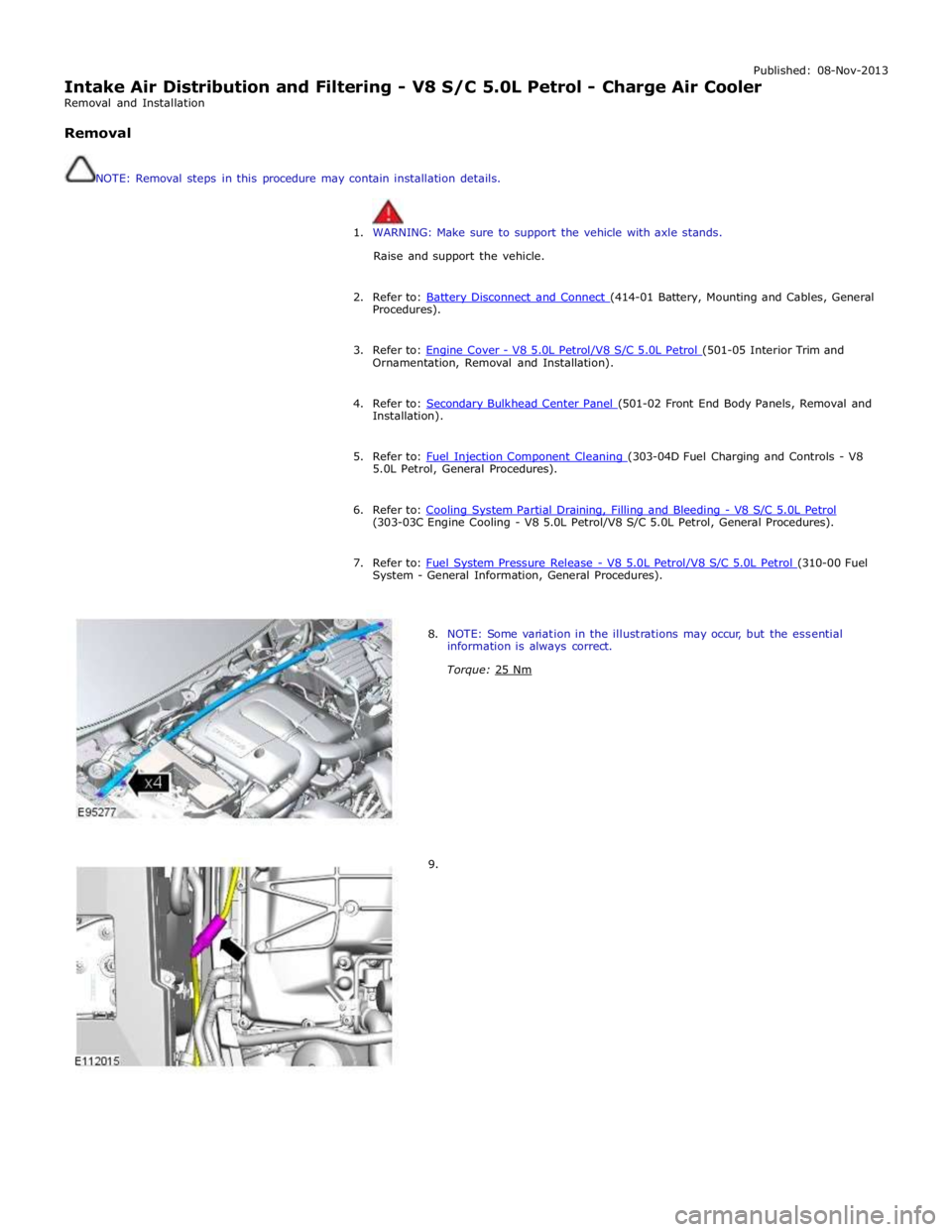
8. NOTE: Some variation in the illustrations may occur, but the essential
information is always correct.
Torque: 25 Nm
9.
Page 1319 of 3039
Published: 30-Jan-2014
Intake Air Distribution and Filtering - V8 S/C 5.0L Petrol - Supercharger
Removal and Installation
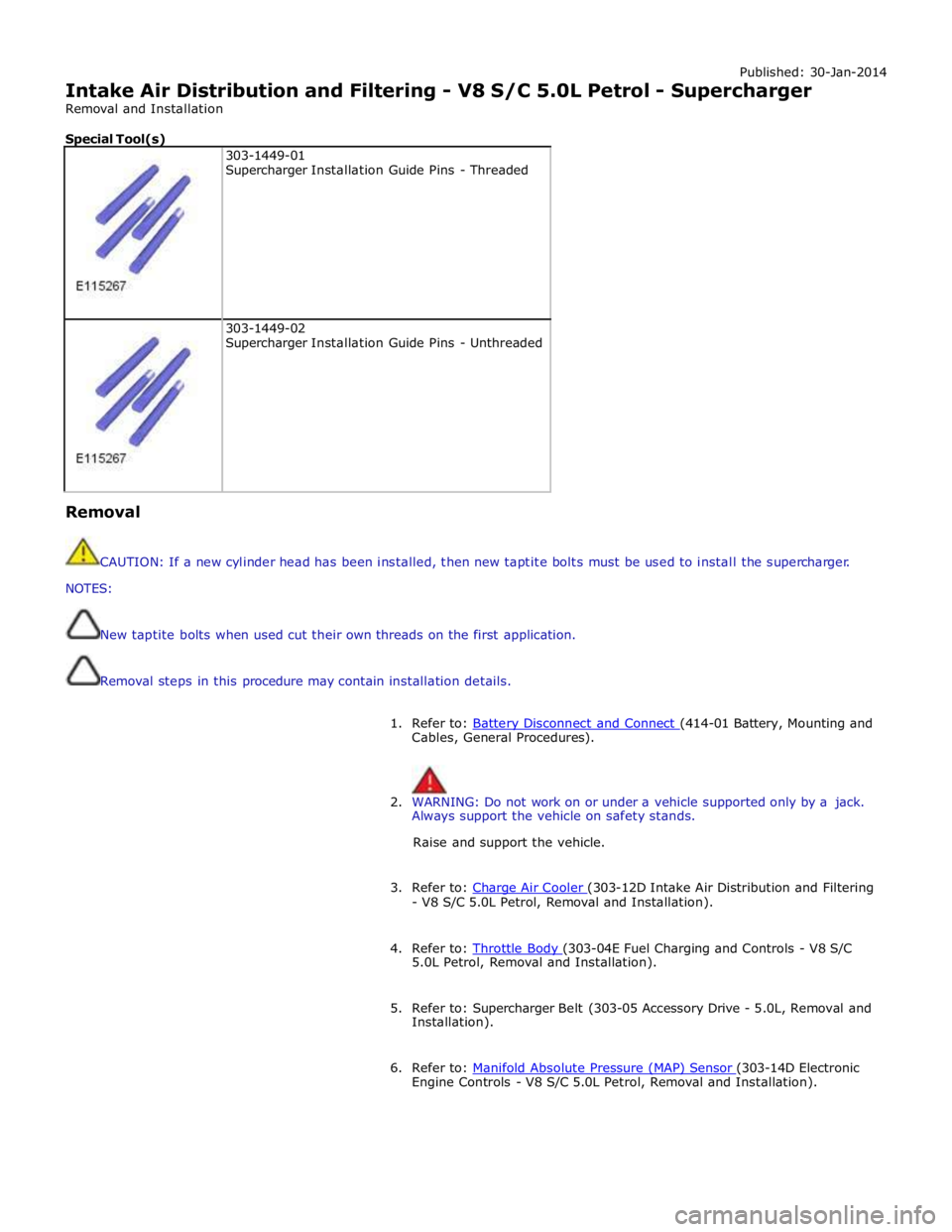
Special Tool(s)
303-1449-01
Supercharger Installation Guide Pins - Threaded
303-1449-02
Supercharger Installation Guide Pins - Unthreaded Removal
CAUTION: If a new cylinder head has been installed, then new taptite bolts must be used to install the supercharger.
NOTES:
New taptite bolts when used cut their own threads on the first application.
Removal steps in this procedure may contain installation details.
1. Refer to: Battery Disconnect and Connect (414-01 Battery, Mounting and Cables, General Procedures).
2. WARNING: Do not work on or under a vehicle supported only by a jack.
Always support the vehicle on safety stands.
Raise and support the vehicle.
3. Refer to: Charge Air Cooler (303-12D Intake Air Distribution and Filtering - V8 S/C 5.0L Petrol, Removal and Installation).
4. Refer to: Throttle Body (303-04E Fuel Charging and Controls - V8 S/C 5.0L Petrol, Removal and Installation).
5. Refer to: Supercharger Belt (303-05 Accessory Drive - 5.0L, Removal and
Installation).
6. Refer to: Manifold Absolute Pressure (MAP) Sensor (303-14D Electronic Engine Controls - V8 S/C 5.0L Petrol, Removal and Installation).
Page 1326 of 3039
Engine Controls - V8 S/C 5.0L Petrol, Removal and Installation).
14. Refer to: Supercharger Belt (303-05 Accessory Drive - 5.0L, Removal and
Installation).
15. Refer to: Throttle Body (303-04E Fuel Charging and Controls - V8 S/C 5.0L Petrol, Removal and Installation).
16. Refer to: Charge Air Cooler (303-12D Intake Air Distribution and Filtering - V8 S/C 5.0L Petrol, Removal and Installation).
17. Refer to: Battery Disconnect and Connect (414-01 Battery, Mounting and Cables, General Procedures). www.JagDocs.com
Page 1327 of 3039
Published: 20-Jun-2014
Intake Air Distribution and Filtering - V8 S/C 5.0L Petrol - Supercharger
Spring Isolator
Removal and Installation
Removal
CAUTION: Make sure that all open ports are covered to prevent any foreign material ingress.
NOTE: Some variation in the illustrations may occur, but the essential information is always correct.
1. WARNING: Make sure to support the vehicle with axle stands.
Raise and support the vehicle.
2. Refer to: Supercharger (303-12D Intake Air Distribution and Filtering - V8 S/C 5.0L Petrol, Removal and Installation).
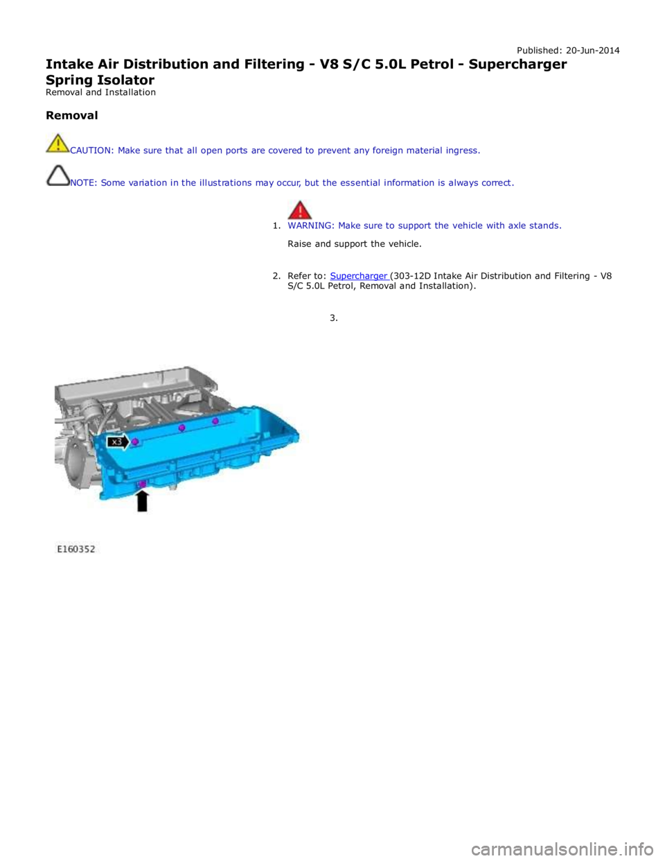
3.
Page 1339 of 3039
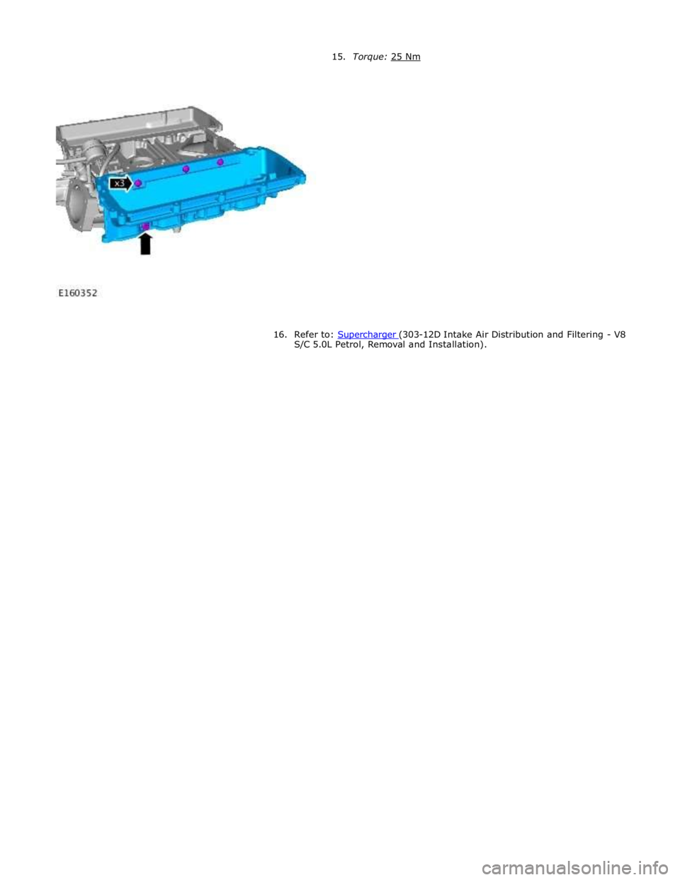
16. Refer to: Supercharger (303-12D Intake Air Distribution and Filtering - V8 S/C 5.0L Petrol, Removal and Installation).
Page 1344 of 3039
Published: 11-May-2011
Evaporative Emissions - V8 5.0L Petrol/V8 S/C 5.0L Petrol - Evaporative Emissions - System Operation and Component Description
Description and Operation
System Operation DIAGNOSTIC MODULE - TANK LEAKAGE PUMP (NAS ONLY)
To check the fuel tank and the EVAP (evaporative emission) system for leaks, the ECM (engine control module) operates the
DMTL pump and monitors the current draw. Initially, the ECM establishes a reference current by pumping air through the reference orifice and back to atmosphere. Once the reference current is determined, the ECM closes the change-over valve, which seals the EVAP system. The EVAP canister purge valve remains de-energized and is therefore closed. The output from the air pump is diverted from the reference orifice and into the EVAP system.
When the change-over valve is closed, the load on the air pump falls to zero. Providing there are no leaks, the air pump will
begin to pressurize the EVAP system and the load and current draw in the pump increases. By monitoring the rate and level of the current increase, the ECM can determine if there is a leak in the EVAP system.
During normal vehicle operation, 15 seconds after the engine has started, the ECM energizes the heating element in the pump to prevent condensation formation and possible incorrect readings. The heater remains energized until either the engine and
ignition are off (if no DMTL test is running) or until after the DMTL test is completed.
Leaks are classified as:
Minor - equivalent to a hole diameter of 0.5 to 1.0 mm (0.02 to 0.04 in.).
Major - equivalent to a hole diameter of 1.0 mm (0.04 in.) or greater.
The ECM performs a check for major leaks each time the ignition is switched off, providing the following conditions are met: The vehicle speed is zero.
The engine speed is zero.
The atmospheric pressure is above 70 kPa (10.15 lbf/in2
), i.e. the altitude is less than approximately 3047 m (10000
feet).
The ambient temperature is between 0 and 40 °C (32 and 104 °F).
The EVAP canister vapor concentration factor is 5 or less (where 0 is no fuel vapor, 1 is stoichiometric fuel vapor and greater than 1 is rich fuel vapor).
The fuel tank level is valid and between 15 and 85% of nominal capacity.
The engine running time during the previous cycle was more than 10 minutes.
The battery voltage is between 10 and 15 volts.
The last engine off time was more than 180 minutes.
No errors are detected with the EVAP components, the ambient air temperature and the fuel level.
NOTE: A leak test can be performed using a Jaguar recognized diagnostic tool. This overrides the above conditions and is
useful for checking correct system and component operation.
The ECM performs a check for minor leaks after every 2nd major leak check.
When the leak check is complete, the ECM stops the DMTL pump and opens (de-energizes) the change-over valve.
If the fuel filler cap is opened or refueling is detected during the leak check, by a sudden drop in the current draw or a rise in
the fuel level, the ECM aborts the leak check.
If a leak is detected during the check, the ECM stores an appropriate fault code in its memory. If a leak is detected on two consecutive checks, the ECM illuminates the MIL (malfunction indicator lamp) in the instrument cluster on the next drive cycle. The duration of a leak check can be between 60 and 900 seconds depending on the results and fuel tank level.
EVAP CANISTER PURGE VALVE
The ECM waits until the engine is running above 55 °C (131 °F) coolant temperature with closed loop fuel operational before the purging process is activated. Under these conditions the engine should be running smoothly with no warm up enrichment.
The EVAP canister purge valve duty (and flow) is initially ramped slowly because the vapor concentration is unknown (a sudden increase in purge could cause unstable engine running or cause it to stall due to an extremely "rich" air/fuel mixture). The
concentration is then determined from the amount of adjustment that the closed loop fueling is required to make to achieve
the target AFR (air fuel ratio). Once the concentration has been determined, the purge flow can be increased rapidly and the
injected fuel can be pro-actively adjusted to compensate for the known purge vapor and the target AIR control is maintained.
When the purging process is active, fresh air is drawn into the EVAP canister via the DMTL filter and pump on NAS vehicles, or via the vent port on the EVAP canister of non NAS vehicles.
Page 1345 of 3039
Component Description DIAGNOSTIC MODULE - TANK LEAKAGE PUMP (NAS ONLY)
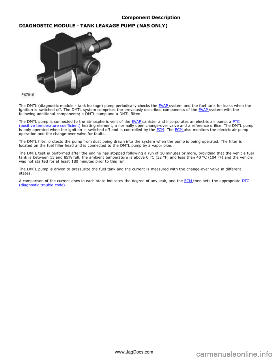
The DMTL (diagnostic module - tank leakage) pump periodically checks the EVAP system and the fuel tank for leaks when the ignition is switched off. The DMTL system comprises the previously described components of the EVAP system with the following additional components; a DMTL pump and a DMTL filter.
The DMTL pump is connected to the atmospheric vent of the EVAP canister and incorporates an electric air pump, a PTC (positive temperature coefficient) heating element, a normally open change-over valve and a reference orifice. The DMTL pump
is only operated when the ignition is switched off and is controlled by the ECM. The ECM also monitors the electric air pump operation and the change-over valve for faults.
The DMTL filter protects the pump from dust being drawn into the system when the pump is being operated. The filter is
located on the fuel filler head and is connected to the DMTL pump by a vapor pipe.
The DMTL test is performed after the engine has stopped following a run of 10 minutes or more, providing that the vehicle fuel
tank is between 15 and 85% full, the ambient temperature is above 0 °C (32 °F) and less than 40 °C (104 °F) and the vehicle
was not started for at least 180 minutes prior to this run.
The DMTL pump is driven to pressurize the fuel tank and the current is measured with the change-over valve in different
states.
A comparison of the current draw in each state indicates the degree of any leak, and the ECM then sets the appropriate DTC (diagnostic trouble code).
www.JagDocs.com
Page 1367 of 3039
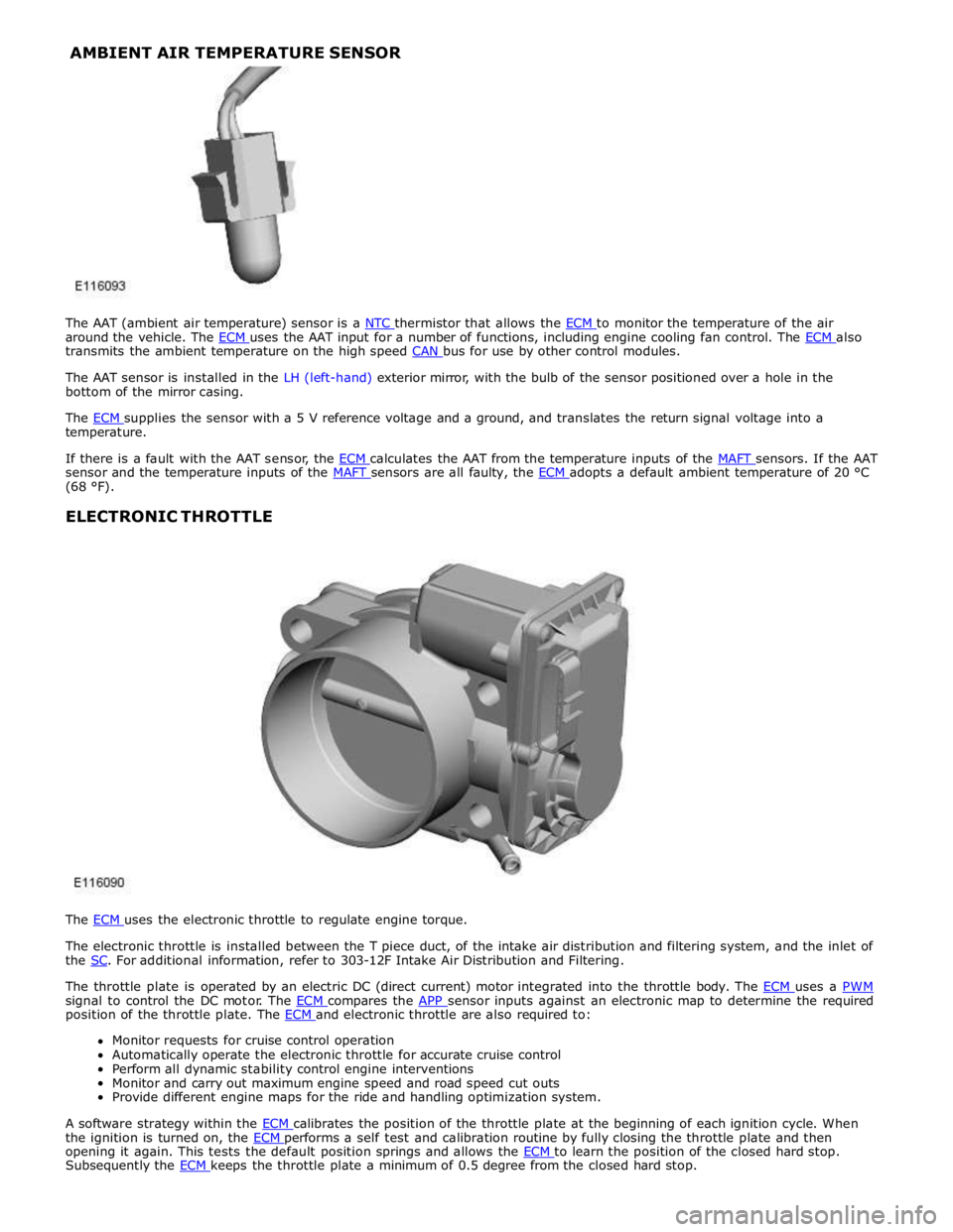
around the vehicle. The ECM uses the AAT input for a number of functions, including engine cooling fan control. The ECM also transmits the ambient temperature on the high speed CAN bus for use by other control modules.
The AAT sensor is installed in the LH (left-hand) exterior mirror, with the bulb of the sensor positioned over a hole in the
bottom of the mirror casing.
The ECM supplies the sensor with a 5 V reference voltage and a ground, and translates the return signal voltage into a temperature.
If there is a fault with the AAT sensor, the ECM calculates the AAT from the temperature inputs of the MAFT sensors. If the AAT sensor and the temperature inputs of the MAFT sensors are all faulty, the ECM adopts a default ambient temperature of 20 °C (68 °F).
ELECTRONIC THROTTLE
The ECM uses the electronic throttle to regulate engine torque.
The electronic throttle is installed between the T piece duct, of the intake air distribution and filtering system, and the inlet of
the SC. For additional information, refer to 303-12F Intake Air Distribution and Filtering.
The throttle plate is operated by an electric DC (direct current) motor integrated into the throttle body. The ECM uses a PWM signal to control the DC motor. The ECM compares the APP sensor inputs against an electronic map to determine the required position of the throttle plate. The ECM and electronic throttle are also required to: Monitor requests for cruise control operation
Automatically operate the electronic throttle for accurate cruise control
Perform all dynamic stability control engine interventions
Monitor and carry out maximum engine speed and road speed cut outs
Provide different engine maps for the ride and handling optimization system.
A software strategy within the ECM calibrates the position of the throttle plate at the beginning of each ignition cycle. When the ignition is turned on, the ECM performs a self test and calibration routine by fully closing the throttle plate and then opening it again. This tests the default position springs and allows the ECM to learn the position of the closed hard stop. Subsequently the ECM keeps the throttle plate a minimum of 0.5 degree from the closed hard stop. AMBIENT AIR TEMPERATURE SENSOR