2010 JAGUAR XFR Electrical
[x] Cancel search: ElectricalPage 2104 of 3039

Wiring Harnesses - Wiring Harness
Description and Operation
Introduction Published: 21-Jan-2014
CAUTION: Do not use any other heat shrink sleeve other than the approved glue lined heat shrink sleeve mentioned in
the repair procedure.
The purpose of this document is to promote quick and efficient minor repair to harness connectors or cables using approved
methods. Repairs may only be made to cables and connectors which have been mechanically, not electrically damaged. It also
applies where the whole extent of the damage can be clearly identified and rectified.
Care and neatness are essential requirements in making a perfect repair.
Caution:
This harness repair guide, does not approve repairs to any of the following circuits:
1. Any media orientated system transport network harnesses.
2. Supplement restraint system (SRS) firing circuits (Air bags).
3. Link lead assembles, which are unique to safety critical circuits such as anti-lock brake system (ABS) and thermocouple
circuits. An example of this is the ABS wheel speed sensors with moulded connectors.
4. 4. Screened cables, leads and wiring harness(s).
If any harness(s) with defective electrical connector terminals or wires from the above circuits are a concern, new
components must be installed.
Repair Components
CAUTION: Where the repair procedure indicates that a glue lined heat shrink sleeve should be applied, apply sufficient
heat to the glue lined heat shrink to melt the glue in order to provide a water tight seal. Do not over heat the glue lined heat
shrink sleeve so that the wiring harness insulation becomes damaged.
The wiring harness repair components comprises:
Pre-terminated wiring harness(s) of different sizes and types
Three sizes of butt splice connectors
A selection of colored cable identification sleeves
Two sizes of glue lined heat shrink sleeves
A suitable heat source, for shrinking heat shrink sleeves will be required.
The pre-insulated diamond grip range of electrical connector terminals and in-line, butt splice connectors are the only
acceptable product for the repairs of wiring harnesses. The butt connectors not only grip the wire but also the insulation,
making a very secure joint.
If an electrical connector terminal is not available approval for the repair is NOT given and in these circumstances a new wiring
harness must be installed.
Pre-Terminated Wiring Harness(s) and Butt Splice Connectors
The pre-terminated wiring harness(s) are supplied with the insulation in one of three colors, red, blue or yellow. The colors do
not apply to any particular circuit but to the harness wire size. See the Relationship Table in the Repair Method section.
Butt splice connectors are also supplied with red, blue or yellow coverings, which must be matched to the pre-terminated
wiring harness insulation color.
Page 2105 of 3039
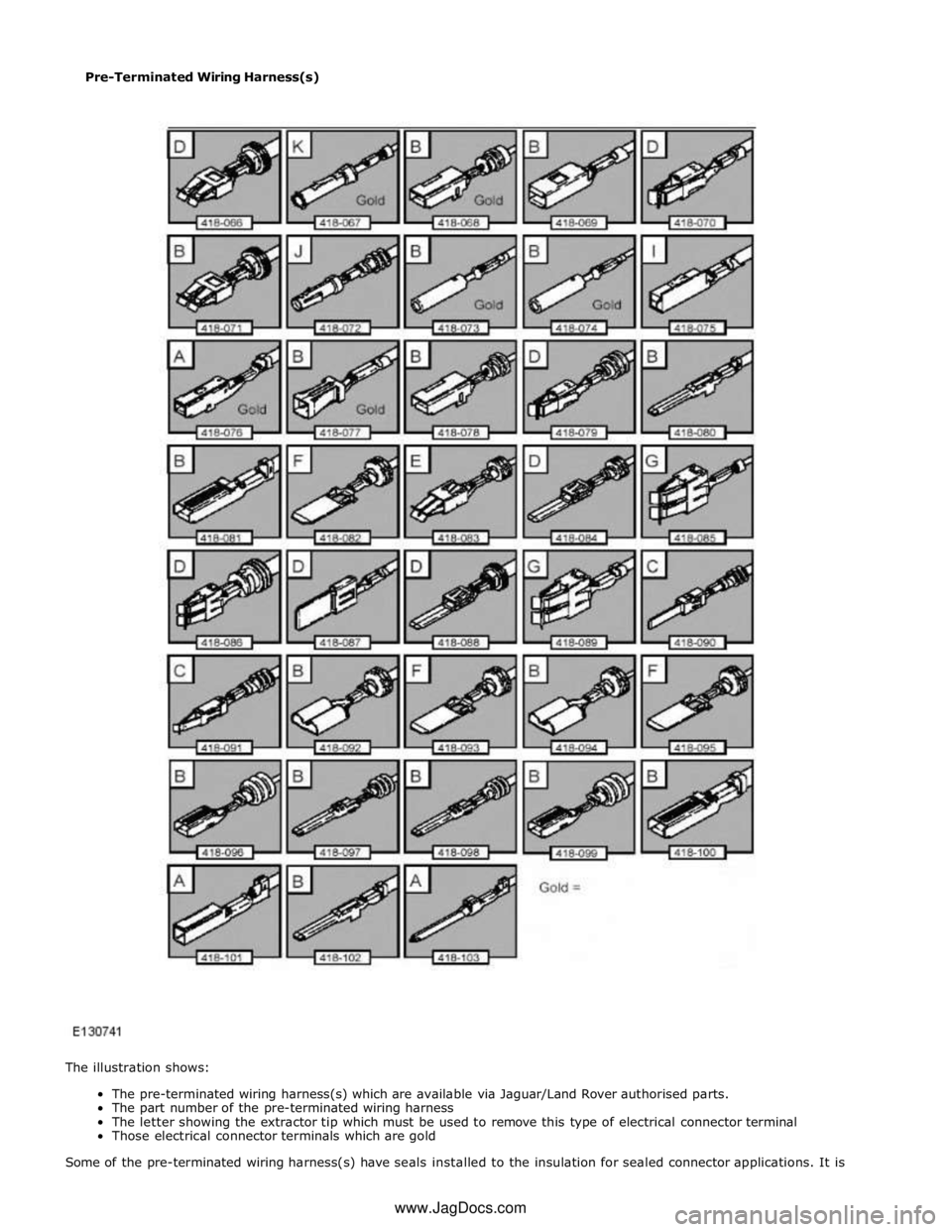
Pre-Terminated Wiring Harness(s)
The illustration shows:
The pre-terminated wiring harness(s) which are available via Jaguar/Land Rover authorised parts.
The part number of the pre-terminated wiring harness
The letter showing the extractor tip which must be used to remove this type of electrical connector terminal
Those electrical connector terminals which are gold
Some of the pre-terminated wiring harness(s) have seals installed to the insulation for sealed connector applications. It is www.JagDocs.com
Page 2106 of 3039

essential for prevention of moisture ingress that a sealed pre-terminated wiring harness must be used where a sealed terminal
was removed.
CAUTION: Where the repair procedure indicates that a glue lined heat shrink sleeve should be applied, apply sufficient
heat to the glue lined heat shrink to melt the glue in order to provide a water tight seal. Do not over heat the glue lined heat
shrink sleeve so that the wiring harness insulation becomes damaged.
Two sizes of heat shrink sleeving are available. Each heat shrink sleeve contains a sealant glue. These must be used when
connecting wiring harness(s) or electrical connector terminal(s) at all times. The smaller diameter heat shrink sleeve is to be
used with the red and blue butt splice connectors and the larger diameter sleeve with the yellow butt splice connectors.
For ease and speed, some of the pre-terminated wiring harness(s) may already have the insulation partly stripped at the splice
end. If the repair requires insulation to be stripped from the cable, refer to the Relationship Table for the correct length of
insulation to be stripped.
The Pre-Terminated Wiring Harness(s) illustration shows the electrical connector terminal type, the part number of the
pre-terminated wiring harness and the letter of the extractor tip which must be used to extract the electrical connector
terminal from the connector housing. Additionally, those electrical connector terminal(s) which are gold are identified, all
others are therefore, tinned and not gold.
Wiring Harness Cable Identification Sleeves
A selection of colored sleeves are available for maintaining the wiring harness cable identification on the pre-terminated wiring
harness. Place the correct colored sleeve(s) over the pre-terminated wiring harness insulation as near to the electrical
connector as possible with the main wiring harness cable color nearest to the electrical connector.
For example, if the original wiring harness cable color is pink with a black trace put the pink wiring harness cable identification
sleeve on the pre-terminated wiring harness first followed by a black sleeve, and slide both along the wiring harness cable to
the electrical connector terminal.
List of Parts
Description Part Number Quantity Pre-Terminated Wiring Harness(s) 418-066 to 418-103
inclusive 10 each Glue Lined Heat Shrink Pack – small diameter 418-104 25 per pack Glue Lined Heat Shrink Pack – larger diameter 418-105 10 per pack Case Assembly Comprising – carry case, lid, inner lid, base, insert, trays foam spacers 418-106 1 Butt Splice Connector – Red 418-107 50 per pack Butt Splice Connector – Blue 418-108 50 per pack Butt Splice Connector – Yellow 418-109 20 per pack Sleeve Identification Pack – for Red insulation 418-112 500 Sleeve Identification Pack – for Blue insulation 418-113 500 Sleeve Identification Pack – for Yellow insulation 418-114 500 Harness repair components can be ordered from Jaguar/Land Rover authorised parts.
Repair Tools
The wiring harness repair tools comprises:
Crimping pliers
A wire cutter and insulation stripper
An electrical connector terminal extraction handle and tips
Extraction Handle and Tips
The extraction handle, in conjunction with the correct tip, is used to remove a terminal from an electrical connector. Each tip is
marked with an identification letter, A to K inclusive. Each tip has been specially designed to extract a particular type of
electrical connector terminal. The use of any other tool is not recommended and is liable to cause damage to the electrical
connector. The tip is fastened to the handle by a screw which holds the tip firmly yet allows it to be easily replaced.
Page 2110 of 3039
Repair Methods
CAUTION: Several different types and sizes of terminal may be found in a single electrical connector housing.
It is necessary to identify:
The conductor (wire) size of the affected wiring harness
The electrical connector range from which the damaged wiring harness is to be removed
The terminal type
Use of the approved diagnostic tool will greatly assist in the quick identification of electrical connectors and faulty pin
terminal(s).
Reference can also be made to the vehicle Electrical Guides, held by Dealers, to identify wiring harness(s) and electrical
connector(s).
By using the Relationship Table, the wiring harness conductor (wire) size can be related to a suitable pre-terminated wiring
harness by the color of the insulation. Also, the correct length of insulation to be stripped from the wiring harness lead is
identified.
Relationship Table
CABLE RANGE SPLICE STRIP LENGTH 0.35 mm² to 1.50 mm² RED 6.00 to 7.00 mm 1.00 mm² to 2.50 mm² BLUE 6.00 to 7.00 mm 4.00 mm² to 6.00 mm² YELLOW 9.00 to 9.50 mm Electrical Connector Terminal Extraction
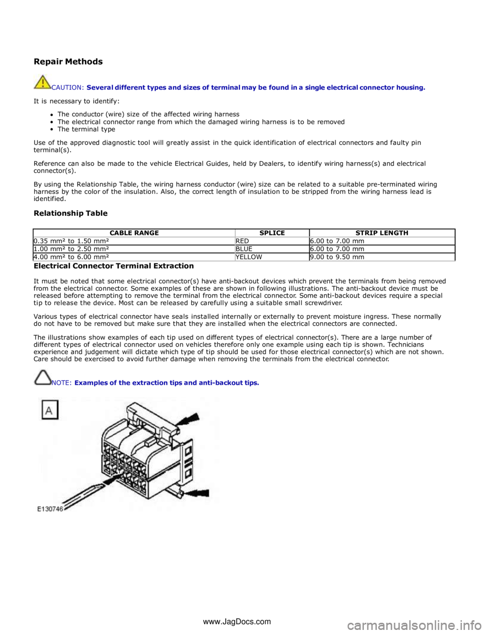
It must be noted that some electrical connector(s) have anti-backout devices which prevent the terminals from being removed
from the electrical connector. Some examples of these are shown in following illustrations. The anti-backout device must be
released before attempting to remove the terminal from the electrical connector. Some anti-backout devices require a special
tip to release the device. Most can be released by carefully using a suitable small screwdriver.
Various types of electrical connector have seals installed internally or externally to prevent moisture ingress. These normally
do not have to be removed but make sure that they are installed when the electrical connectors are connected.
The illustrations show examples of each tip used on different types of electrical connector(s). There are a large number of
different types of electrical connector used on vehicles therefore only one example using each tip is shown. Technicians
experience and judgement will dictate which type of tip should be used for those electrical connector(s) which are not shown.
Care should be exercised to avoid further damage when removing the terminals from the electrical connector.
NOTE: Examples of the extraction tips and anti-backout tips.
www.JagDocs.com
Page 2114 of 3039
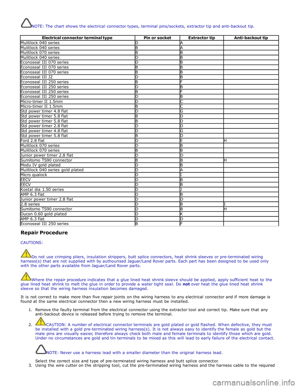
NOTE: The chart shows the electrical connector types, terminal pins/sockets, extractor tip and anti-backout tip.
Electrical connector terminal type Pin or socket Extractor tip Anti-backout tip Mulitlock 040 series D A Mulitlock 040 series B A Mulitlock 070 series B B Mulitlock 040 series D B Econoseal III 070 series D B Econoseal III 070 series B B Econoseal III 070 series B B Econoseal III J2 D B Econoseal III 250 series B F Econoseal III 250 series D B Econoseal III 250 series B F Econoseal III 250 series D B Micro-timer II 1.5mm D C Micro-timer II 1.5mm B C Std power timer 4.8 flat D G Std power timer 5.8 flat B D Std power timer 5.8 flat B D Std power timer 2.8 flat D D Std power timer 4.8 flat D G Std power timer 5.8 flat B D Ford 2.8 flat D E H Mulitlock 070 series D B Mulitlock 070 series B B Junior power timer 2.8 flat D D Sumitomo TS90 connector B B H Modu IV gold plated D B Mulitlock 040 series gold plated D A Micro qualock D I EECV D B EECV D B Kostal dia 1.50 series D J AMP 6.3 flat D B Junior power timer 2.8 flat D D 2.8 series D B I Sumitomo TS90 connector D B H Ducon 0.60 gold plated D K AMP 6.3 flat D D Econoseal III 250 series B F Repair Procedure
CAUTIONS:
Do not use crimping pliers, insulation strippers, butt splice connectors, heat shrink sleeves or pre-terminated wiring
harness(s) that are not supplied with by authourised Jaguar/Land Rover parts. Each part has been designed to be used only
with the other parts available from Jaguar/Land Rover parts.
Where the repair procedure indicates that a glue lined heat shrink sleeve should be applied, apply sufficient heat to the
glue lined heat shrink to melt the glue in order to provide a water tight seal. Do not over heat the glue lined heat shrink
sleeve so that the wiring harness insulation becomes damaged.
It is not correct to make more than five repair joints on the wiring harness to any electrical connector and if more damage is
found at the same electrical connector then a new wiring harness must be installed.
1. Remove the faulty terminal from the electrical connector using the extractor tool and correct tip. Make sure that any
anti-backout device is released before trying to remove the terminal.
2. CAUTION: A number of electrical connector terminals are gold plated or gold flashed. When defective, they must
be installed with a gold pre-terminated wiring harness(s). It is not always easy to identify the female as gold but the
male pins are visually easier, therefore always check both male and female terminals to identify those which are gold.
Under no circumstances are gold and tin terminals to be mixed as this will lead to early failure of the electrical contact.
NOTE: Never use a harness lead with a smaller diameter than the original harness lead.
Select the correct size and type of pre-terminated wiring harness and butt splice connector.
3. Using the wire cutter on the stripping tool, cut the pre-terminated wiring harness and the harness cable to the required
Page 2115 of 3039
length.
4.
5.
6.
7.
8.
9.
10.
11.
12.
13.
14.
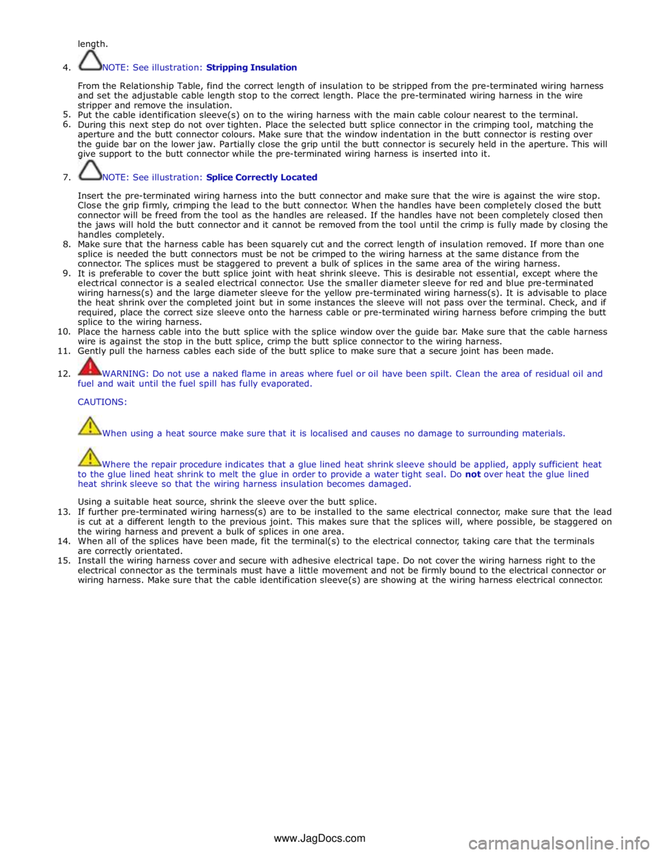
15. NOTE: See illustration: Stripping Insulation
From the Relationship Table, find the correct length of insulation to be stripped from the pre-terminated wiring harness
and set the adjustable cable length stop to the correct length. Place the pre-terminated wiring harness in the wire
stripper and remove the insulation.
Put the cable identification sleeve(s) on to the wiring harness with the main cable colour nearest to the terminal.
During this next step do not over tighten. Place the selected butt splice connector in the crimping tool, matching the
aperture and the butt connector colours. Make sure that the window indentation in the butt connector is resting over
the guide bar on the lower jaw. Partially close the grip until the butt connector is securely held in the aperture. This will
give support to the butt connector while the pre-terminated wiring harness is inserted into it.
NOTE: See illustration: Splice Correctly Located
Insert the pre-terminated wiring harness into the butt connector and make sure that the wire is against the wire stop.
Close the grip firmly, crimping the lead to the butt connector. When the handles have been completely closed the butt
connector will be freed from the tool as the handles are released. If the handles have not been completely closed then
the jaws will hold the butt connector and it cannot be removed from the tool until the crimp is fully made by closing the
handles completely.
Make sure that the harness cable has been squarely cut and the correct length of insulation removed. If more than one
splice is needed the butt connectors must be not be crimped to the wiring harness at the same distance from the
connector. The splices must be staggered to prevent a bulk of splices in the same area of the wiring harness.
It is preferable to cover the butt splice joint with heat shrink sleeve. This is desirable not essential, except where the
electrical connector is a sealed electrical connector. Use the smaller diameter sleeve for red and blue pre-terminated
wiring harness(s) and the large diameter sleeve for the yellow pre-terminated wiring harness(s). It is advisable to place
the heat shrink over the completed joint but in some instances the sleeve will not pass over the terminal. Check, and if
required, place the correct size sleeve onto the harness cable or pre-terminated wiring harness before crimping the butt
splice to the wiring harness.
Place the harness cable into the butt splice with the splice window over the guide bar. Make sure that the cable harness
wire is against the stop in the butt splice, crimp the butt splice connector to the wiring harness.
Gently pull the harness cables each side of the butt splice to make sure that a secure joint has been made.
WARNING: Do not use a naked flame in areas where fuel or oil have been spilt. Clean the area of residual oil and
fuel and wait until the fuel spill has fully evaporated.
CAUTIONS:
When using a heat source make sure that it is localised and causes no damage to surrounding materials.
Where the repair procedure indicates that a glue lined heat shrink sleeve should be applied, apply sufficient heat
to the glue lined heat shrink to melt the glue in order to provide a water tight seal. Do not over heat the glue lined
heat shrink sleeve so that the wiring harness insulation becomes damaged.
Using a suitable heat source, shrink the sleeve over the butt splice.
If further pre-terminated wiring harness(s) are to be installed to the same electrical connector, make sure that the lead
is cut at a different length to the previous joint. This makes sure that the splices will, where possible, be staggered on
the wiring harness and prevent a bulk of splices in one area.
When all of the splices have been made, fit the terminal(s) to the electrical connector, taking care that the terminals
are correctly orientated.
Install the wiring harness cover and secure with adhesive electrical tape. Do not cover the wiring harness right to the
electrical connector as the terminals must have a little movement and not be firmly bound to the electrical connector or
wiring harness. Make sure that the cable identification sleeve(s) are showing at the wiring harness electrical connector.
www.JagDocs.com
Page 2123 of 3039
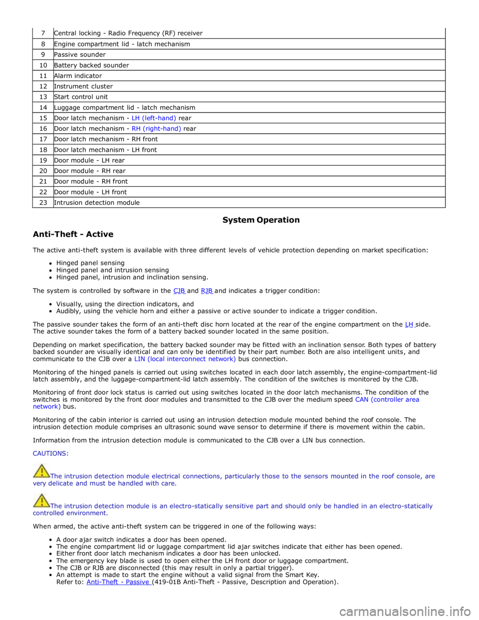
7 Central locking - Radio Frequency (RF) receiver 8 Engine compartment lid - latch mechanism 9 Passive sounder 10 Battery backed sounder 11 Alarm indicator 12 Instrument cluster 13 Start control unit 14 Luggage compartment lid - latch mechanism 15 Door latch mechanism - LH (left-hand) rear 16 Door latch mechanism - RH (right-hand) rear 17 Door latch mechanism - RH front 18 Door latch mechanism - LH front 19 Door module - LH rear 20 Door module - RH rear 21 Door module - RH front 22 Door module - LH front 23 Intrusion detection module
Anti-Theft - Active System Operation
The active anti-theft system is available with three different levels of vehicle protection depending on market specification:
Hinged panel sensing
Hinged panel and intrusion sensing
Hinged panel, intrusion and inclination sensing.
The system is controlled by software in the CJB and RJB and indicates a trigger condition: Visually, using the direction indicators, and
Audibly, using the vehicle horn and either a passive or active sounder to indicate a trigger condition.
The passive sounder takes the form of an anti-theft disc horn located at the rear of the engine compartment on the LH side. The active sounder takes the form of a battery backed sounder located in the same position.
Depending on market specification, the battery backed sounder may be fitted with an inclination sensor. Both types of battery
backed sounder are visually identical and can only be identified by their part number. Both are also intelligent units, and
communicate to the CJB over a LIN (local interconnect network) bus connection.
Monitoring of the hinged panels is carried out using switches located in each door latch assembly, the engine-compartment-lid
latch assembly, and the luggage-compartment-lid latch assembly. The condition of the switches is monitored by the CJB.
Monitoring of front door lock status is carried out using switches located in the door latch mechanisms. The condition of the
switches is monitored by the front door modules and transmitted to the CJB over the medium speed CAN (controller area
network) bus.
Monitoring of the cabin interior is carried out using an intrusion detection module mounted behind the roof console. The
intrusion detection module comprises an ultrasonic sound wave sensor to determine if there is movement within the cabin.
Information from the intrusion detection module is communicated to the CJB over a LIN bus connection.
CAUTIONS:
The intrusion detection module electrical connections, particularly those to the sensors mounted in the roof console, are
very delicate and must be handled with care.
The intrusion detection module is an electro-statically sensitive part and should only be handled in an electro-statically
controlled environment.
When armed, the active anti-theft system can be triggered in one of the following ways:
A door ajar switch indicates a door has been opened.
The engine compartment lid or luggage compartment lid ajar switches indicate that either has been opened.
Either front door latch mechanism indicates a door has been unlocked.
The emergency key blade is used to open either the LH front door or luggage compartment.
The CJB or RJB are disconnected (this may result in only a partial trigger).
An attempt is made to start the engine without a valid signal from the Smart Key.
Refer to: Anti-Theft - Passive (419-01B Anti-Theft - Passive, Description and Operation).
Page 2126 of 3039
Anti-Theft - Active - Anti-Theft - Active
Diagnosis and Testing
Principles of Operation Published: 26-Feb-2014
For a detailed description of the anti-theft - active system, refer to the relevant Description and Operation sections in the
workshop manual. REFER to: (419-01A Anti-Theft - Active)
Anti-Theft - Active (Description and Operation), Anti-Theft - Active (Description and Operation), Anti-Theft - Active (Description and Operation).
Inspection and Verification
CAUTION: Diagnosis by substitution from a donor vehicle is NOT acceptable. Substitution of control modules does not
guarantee confirmation of a fault, and may also cause additional faults in the vehicle being tested and/or the donor vehicle.
1. Verify the customer concern.
2. Visually inspect for obvious signs of damage and system integrity.
Visual Inspection
Mechanical Electrical
Door latch micro switches
Hood ajar switch
Passive anti-theft alarm horn (if installed)
Battery backed sounder (if installed) or battery backed sounder with tilt sensor (if
installed)
Vehicle horns
Fuse(s)
Electrical
connector(s)
Wiring Harness
3. If an obvious cause for an observed or reported concern is found, correct the cause (if possible) before proceeding to
the next step.
4. If the cause is not visually evident, check for Diagnostic Trouble Codes (DTCs) and refer to the relevant DTC Index. For
additional diagnosis and testing information, refer to the relevant Diagnosis and Testing section in the workshop
manual
REFER to: Remote Keyless Entry (RKE) Module (419-10 Multifunction Electronic Modules, Diagnosis and Testing).
DTC Index
CAUTION: Diagnosis by substitution from a donor vehicle is NOT acceptable. Substitution of control modules does not
guarantee confirmation of a fault, and may also cause additional faults in the vehicle being tested and/or the donor vehicle
NOTES:
If the control module or a component is suspect and the vehicle remains under manufacturer warranty, refer to the
Warranty Policy and Procedures manual (section B1.2), or determine if any prior approval programme is in operation, prior to
the installation of a new module/component.
Generic scan tools may not read the codes listed, or may read only five digit codes. Match the five digits from the scan
tool to the first five digits of the seven digit code listed to identify the fault (the last two digits give additional information
read by the manufacturer approved diagnostic system).
When performing electrical voltage or resistance tests, always use a digital multimeter (DMM) accurate to three decimal
places, and with an up-to-date calibration certificate. When testing resistance, always take the resistance of the DMM leads
into account.
Check and rectify basic faults before beginning diagnostic routines involving pinpoint tests.
Inspect connectors for signs of water ingress, and pins for damage and/or corrosion.
If DTCs are recorded and, after performing the pinpoint tests, a fault is not present, an intermittent concern may be the
cause. Always check for loose connections and corroded terminals.