2010 JAGUAR XFR Bolt
[x] Cancel search: BoltPage 324 of 3039
Published: 14-Feb-2012
Suspension System - General Information - Front Wheel Bearing and Wheel Hub Runout Check Vehicles With: High Performance Brakes
General Procedures
NOTES:
Some variation in the illustrations may occur, but the essential information is always correct.
RH illustration shown, LH similar.
1. WARNING: Make sure to support the vehicle with axle stands.
Raise the front of the vehicle.
2. Remove the front wheel.
For additional information, refer to: Wheel and Tire (204-04 Wheels and Tires, Removal and Installation).
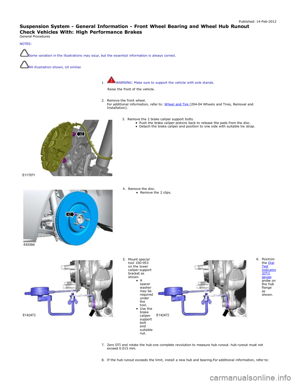
3. Remove the 2 brake caliper support bolts.
Push the brake caliper pistons back to release the pads from the disc. Detach the brake caliper and position to one side with suitable tie strap.
4. Remove the disc.
Remove the 2 clips.
5. Mount special tool 100-053 on the lower caliper support bracket as shown.
A
spacer washer may be required under the tool.
Use the brake caliper support bolt and suitable nut. 6. Position
the Dial Test Indicator (DTI) gauge probe on the hub flange as shown.
7. Zero DTI and rotate the hub one complete revolution to measure hub runout. hub runout must not exceed 0.015 mm.
8. If the hub runout exceeds the limit, install a new hub and bearing.For additional information, refer to:
Page 325 of 3039
Front Wheel Bearing and Wheel Hub - TDV6 3.0L Diesel /V8 5.0L Petrol/V8 S/C 5.0L Petrol (Removal and Installation).
9. If the hub runout is within the limit install the removed components.
10. tighten the brake caliper bolts to 115 Nm.
Page 326 of 3039
Published:
27-Feb-2012
Suspension System - General Information - Rear Wheel Bearing and Wheel
Hub Ru
nout Check
General Procedures
NOTES:
RH illustra tion shown, LH sim ilar.
Some variat ion i n the illustra tions may o ccur, but the es senti al informa tion is always co rrect.
It is recommended that the DTI is capable of measurements of 0.005 mm.
1. WARNING: Make sure to support the vehicle with axle stands.
Raise the rear of the vehicle.
2. Remove the rear wheel.
For additional information, refer to: Wheel and Tire (204-04 Wheels and Tires, Removal and Installation).
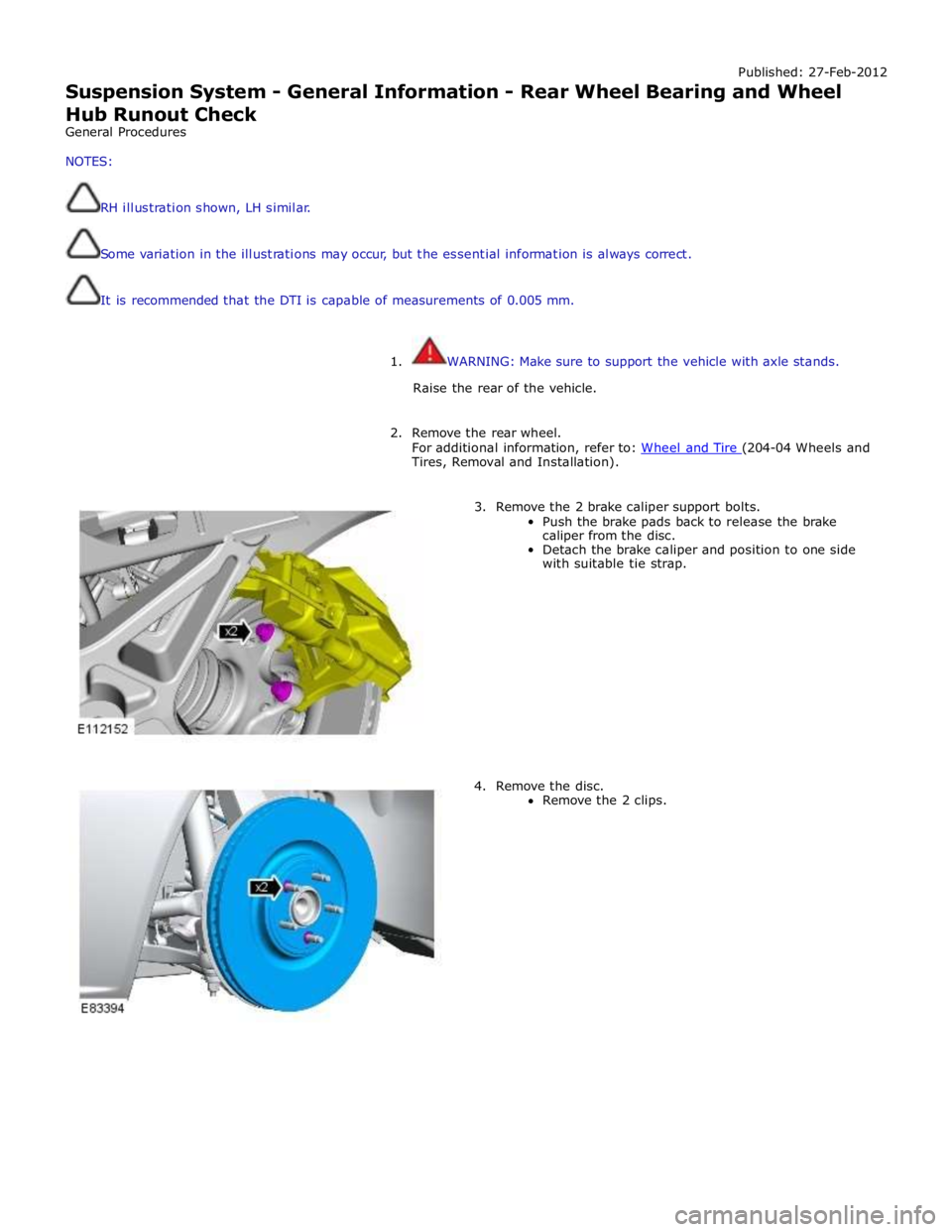
3. Remove the 2 brake caliper support bolts.
Push the brake pads back to release the brake
caliper from the disc.
Detach the brake caliper and position to one side
with suitable tie strap.
4. Remove the disc.
Remove the 2 clips.
Page 327 of 3039
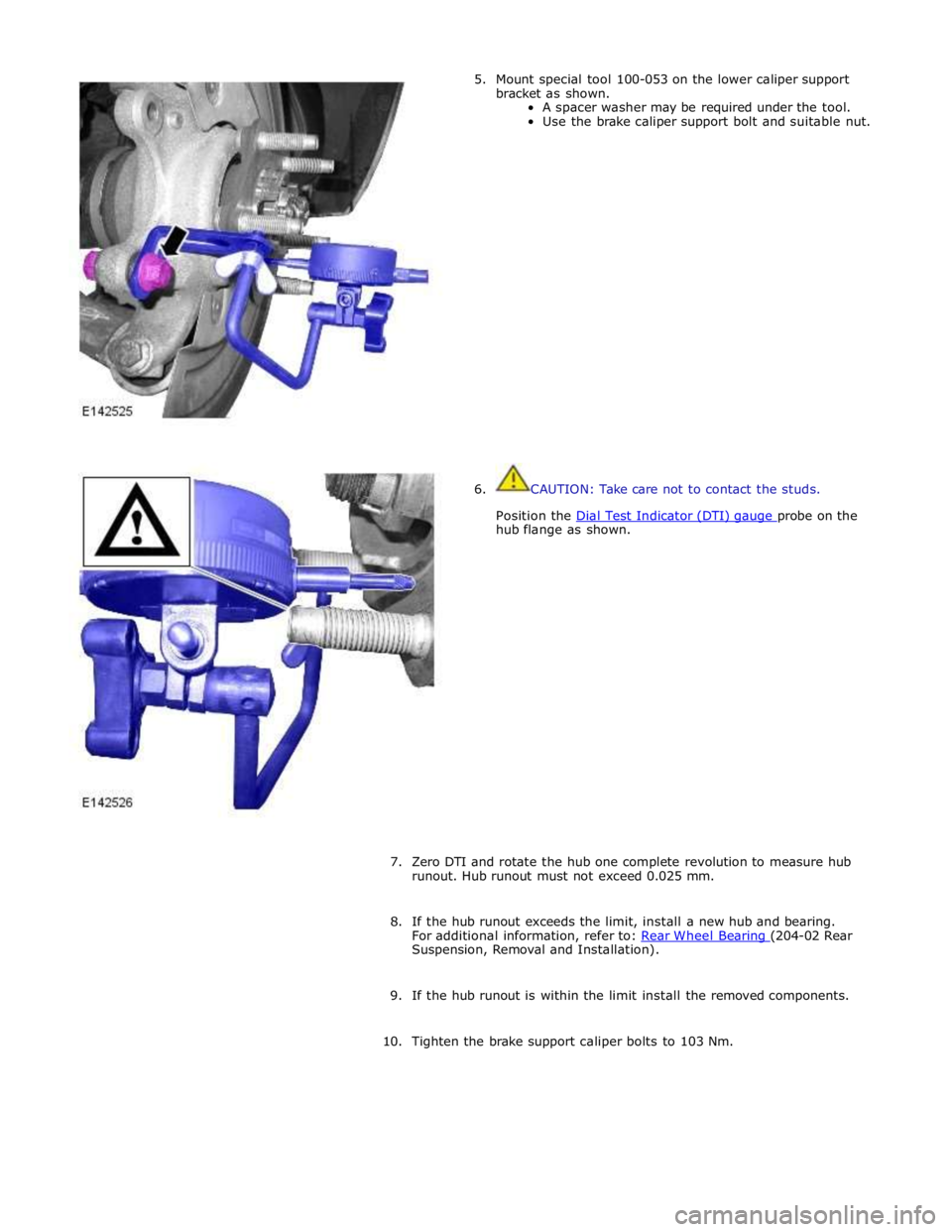
hub flange as shown.
7. Zero DTI and rotate the hub one complete revolution to measure hub
runout. Hub runout must not exceed 0.025 mm.
8. If the hub runout exceeds the limit, install a new hub and bearing.
For additional information, refer to: Rear Wheel Bearing (204-02 Rear Suspension, Removal and Installation).
9. If the hub runout is within the limit install the removed components.
10. Tighten the brake support caliper bolts to 103 Nm.
Page 328 of 3039

Steering gear to subframe retaining bolts 100 74 - Toe link ball joint to wheel knuckle retaining nut 133 98 - Stabilizer bar link to stabilizer bar retaining nut 43 32 - Stabilizer bar link to lower arm retaining nut and bolt 70 52 - Stabilizer bar clamp to subframe retaining bolts 55 41 - Rear lower arm to wheel knuckle ball joint retaining nut 75 55 - Rear lower arm to subframe retaining nut and bolt 175 129 - Front lower arm to subframe retaining nut and bolt 175 129 - Front lower arm to rear lower arm retaining nut and bolt
Stage 1 - 60 Stage 2 - 135 degrees Stage 1 - 44 Stage 2 - 135 degrees - Upper arm ball joint to wheel knuckle retaining nut 90 66 - Upper arm to body retaining nuts and bolts 47 35 - Shock absorber and spring assembly upper mounting to body retaining nuts 28 20 - Shock absorber and spring assembly to lower arm retaining nut and
bolt 175 129 - Shock absorber and spring assembly upper mounting retaining nut (without adaptive damping) 50 37 - Shock absorber and spring assembly upper mounting retaining nut (with adaptive damping) 27 20 - Wheel hub and bearing assembly to wheel knuckle retaining bolt 90 66 - Wheel and tire to wheel hub retaining nuts 125 92 -
Page 332 of 3039

Upper Control Arm
The forged-aluminum upper control arm is a wishbone design and connects to the vehicle body through two plain bushes, and
links to the swan neck wheel knuckle by an integral ball joint. The upper control arm is inclined to provide anti-dive
characteristics under heavy braking, while also controlling geometry for vehicle straight-line stability.
Lower Control Arm
The forged aluminum lower control arms are of the wishbone design; the arms separate to allow for optimum bush tuning:
The rear lateral control arm is fitted with a bush at its inner end which locates between brackets on the subframe. The
arm is secured with an eccentric bolt which provides the adjustment of the suspension camber geometry. The outer end
of the control arm has a tapered hole which locates on a ball joint fitted to the wheel knuckle. An integral clevis bracket
on the forward face of the lateral control arm allows for the attachment of the forward control arm. A bush is fitted
below the clevis bracket to provide for the attachment of the stabilizer bar link. A cross-axis joint is fitted to a
cross-hole in the control arm to provide the location for the clevis attachment of the spring and damper assembly.
The forward control arm is fitted with a fluid-block rubber bush at its inner end which locates between brackets on the
subframe. The arm is secured with an eccentric bolt which provides adjustment of the castor and camber geometry. The
outer end of the control arm is fitted with a cross-axis joint and locates in the integral clevis bracket on the lateral
control arm.
Wheel Knuckle
The cast aluminum wheel knuckle is a swan neck design and attaches to the upper control arm and lower lateral control arm.
The lower lateral control arm locates on a non serviceable ball-joint integral with the wheel knuckle. The lower boss on the
rear of the knuckle provides for the attachment of the steering gear tie-rod ball joint.
The wheel knuckle also provides the mounting locations for the:
wheel hub and bearing assembly
the wheel speed sensor (integral to the wheel hub and bearing assembly)
brake caliper and disc shield.
Stabilizer Bar
The stabilizer bar is attached to the front of the subframe with bushes and mounting brackets. The pressed steel mounting
brackets locate over the bushes and are attached to the cross member with bolts screwed into threaded locations in the
subframe. The stabilizer bar has crimped, 'anti-shuffle' collars pressed in position on the inside edges of the bushes. The
collars prevent sideways movement of the stabilizer bar.
The stabilizer bar is manufactured from 32mm diameter tubular steel on supercharged models and 31mm diameter tubular
steel on diesel and normally aspirated models and has been designed to provide particular characteristics in maintaining roll
rates, specifically in primary ride comfort.
Each end of the stabilizer bar curves rearwards to attach to a ball joint on a stabilizer link. Each stabilizer link is secured to a
bush in the lower lateral arm with a bolt and locknut. The links allow the stabilizer bar to move with the wheel travel providing
maximum effectiveness.
The only difference between the front stabilizer bars, in addition to the diameter, is in the shape to accommodate engine
variant:
a slightly curved bar, between bush centers, for V6 diesel (31 mm dia) and V8 gasoline supercharged (32 mm dia),
a straight bar, between bush centers, for V6 and V8 normally aspirated gasoline engines (31 mm dia).
Spring and Damper Assembly
The spring and damper assemblies are located between the lower lateral arm and the front suspension housing in the inner
wing. Dependant on vehicle model there are three types of coil spring and damper available:
a standard oil passive damper (All models except supercharged),
an adaptive damper, also known as Computer Active Technology Suspension (CATS) on 4.2L supercharged vehicles up to
2010MY, For additional information refer to Vehicle Dynamic Suspension 4.2L.
a continuously variable adaptive damper, also known as Adaptive Dynamics System on 5.0L supercharged vehicles from
2010MY. For additional information refer to Vehicle Dynamic Suspension 5.0L.
The dampers are a monotube design with a spring seat secured by a circlip onto the damper tube. The damper's lower
spherical joint is an integral part of the lateral lower control-arm, and the damper takes the form of a clevis-end, which
straddles the spherical joint.
The damper piston is connected to a damper rod which is sealed at its exit point from the damper body. The threaded outer
end of the damper rod locates through a hole in the top mount. A self locking nut secures the top mount to the damper rod.
The damper rod on the adaptive damper has an electrical connector on the outer end of the damper rod.
Supercharged 4.2L vehicles up to 2010MY: The adaptive damper functions by restricting the flow of hydraulic fluid through
internal galleries in the damper's piston. The adaptive damper has a solenoid operated valve, which when switched allows a
greater flow of hydraulic fluid through the damper's piston. This provides a softer damping characteristic from the damper. The
adaptive damper defaults to a firmer setting when not activated. The solenoid is computer controlled and can switch between
soft and hard damping settings depending on road wheel inputs and vehicle speed.
Supercharged 5.0L vehicles from 2010MY: The variable damper functions by adjustment of a solenoid operated variable orifice,
which opens up an alternative path for oil flow within the damper. When de-energized the bypass is closed and all the oil flows
Page 341 of 3039
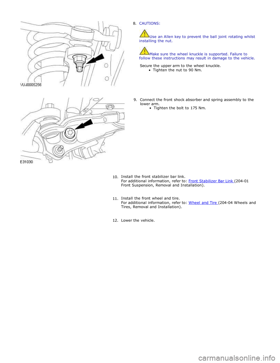
8. CAUTIONS:
Use an Allen key to prevent the ball joint rotating whilst
installing the nut.
Make sure the wheel knuckle is supported. Failure to
follow these instructions may result in damage to the vehicle.
Secure the upper arm to the wheel knuckle.
Tighten the nut to 90 Nm.
9. Connect the front shock absorber and spring assembly to the
lower arm.
Tighten the bolt to 175 Nm.
10. Install the front stabilizer bar link.
For additional information, refer to: Front Stabilizer Bar Link (204-01 Front Suspension, Removal and Installation).
11. Install the front wheel and tire.
For additional information, refer to: Wheel and Tire (204-04 Wheels and Tires, Removal and Installation).
12. Lower the vehicle.
Page 342 of 3039
Front Suspension - Front Lower Arm
Removal and Installation
Removal Published: 11-May-2011
1. WARNING: Do not work on or under a vehicle supported only by a
jack. Always support the vehicle on safety stands.
Raise and support the vehicle.
2. Remove the air deflector.
For additional information, refer to: Air Deflector (501-02 Front End Body Panels, Removal and Installation).
3. Remove the front wheel and tire.
For additional information, refer to: Wheel and Tire (204-04 Wheels and Tires, Removal and Installation).
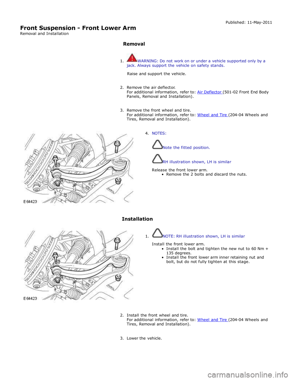
4. NOTES:
Note the fitted position.
RH illustration shown, LH is similar
Release the front lower arm.
Remove the 2 bolts and discard the nuts.
Installation
1. NOTE: RH illustration shown, LH is similar
Install the front lower arm.
Install the bolt and tighten the new nut to 60 Nm +
135 degrees.
Install the front lower arm inner retaining nut and
bolt, but do not fully tighten at this stage.
2. Install the front wheel and tire.
For additional information, refer to: Wheel and Tire (204-04 Wheels and Tires, Removal and Installation).
3. Lower the vehicle.