2010 JAGUAR XFR ESP
[x] Cancel search: ESPPage 1889 of 3039
Battery, Mounting and Cables - Battery
Diagnosis and Testing
Principles of Operation Published: 10-Mar-2014
For a detailed description of the battery system and operation, refer to the relevant Description and Operation section of the
workshop manual. REFER to: Battery and Cables (414-01 Battery, Mounting and Cables, Description and Operation).
Inspection and Verification
CAUTION: Diagnosis by substitution from a donor vehicle is NOT acceptable. Substitution of control modules does not
guarantee confirmation of a fault and may also cause additional faults in the vehicle being checked and/or the donor vehicle.
NOTES:
Generic scan tools may not read the codes listed, or may read only five digit codes. Match the five digits from the scan
tool to the first five digits of the seven digit code listed to identify the fault (the last two digits give additional information
read by the manufacturer-approved diagnostic system).
When performing electrical voltage or resistance tests, always use a digital multimeter (DMM) accurate to three decimal
places, and with an up-to-date calibration certificate. When testing resistance, always take the resistance of the DMM leads
into account.
Check and rectify basic faults before beginning diagnostic routines involving pinpoint tests.
If DTCs are recorded and, after performing the pinpoint tests, a fault is not present, an intermittent concern may be the
cause. Always check for loose connections and corroded terminals.
1. Verify the customer concern.
2. Visually inspect for obvious signs of mechanical or electrical damage.
Visual Inspection
Mechanical Electrical
Generator
Drive belt
Drive belt tensioner
Generator pulley
Check the security of the generator fixings
Generator
Battery
Battery connections
Starter motor
Harnesses and connectors
Fuses
Charge warning lamp function
Engine Control Module (ECM)
3. If an obvious cause for an observed or reported concern is found, correct the cause (if possible) before proceeding to
the next step.
4. If the cause is not visually evident check for Diagnostic Trouble Codes (DTCs) and refer to the DTC Index.
5. Check DDW for open campaigns. Refer to the corresponding bulletins and SSMs which may be valid for the specific
customer complaint and carry out the recommendations as required
Symptom Chart
Symptom Possible Causes Action
Battery power to vehicle
interrupted
High resistance between battery terminals and
clamps
GO to Pinpoint Test
A. Midtronics EXP-1080 User Guide
Carry out the following: -
Surface Voltage Removal Process
A vehicle which has had its battery charged or been driven in a 24 hour period before the test, must have its surface charge
removed
Page 1955 of 3039
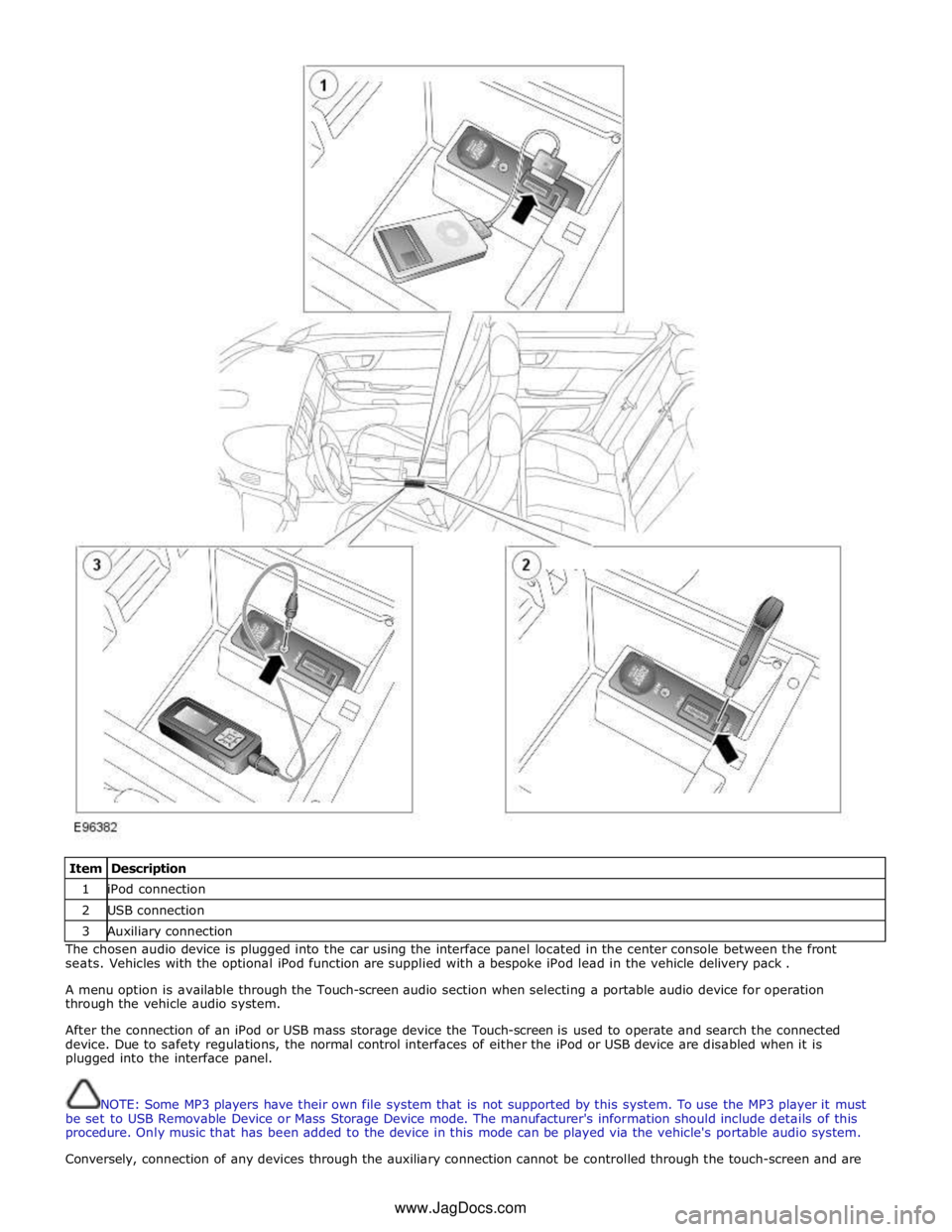
Item Description 1 iPod connection 2 USB connection 3 Auxiliary connection The chosen audio device is plugged into the car using the interface panel located in the center console between the front
seats. Vehicles with the optional iPod function are supplied with a bespoke iPod lead in the vehicle delivery pack .
A menu option is available through the Touch-screen audio section when selecting a portable audio device for operation
through the vehicle audio system.
After the connection of an iPod or USB mass storage device the Touch-screen is used to operate and search the connected
device. Due to safety regulations, the normal control interfaces of either the iPod or USB device are disabled when it is
plugged into the interface panel.
NOTE: Some MP3 players have their own file system that is not supported by this system. To use the MP3 player it must
be set to USB Removable Device or Mass Storage Device mode. The manufacturer's information should include details of this
procedure. Only music that has been added to the device in this mode can be played via the vehicle's portable audio system.
Conversely, connection of any devices through the auxiliary connection cannot be controlled through the touch-screen and are www.JagDocs.com
Page 1982 of 3039
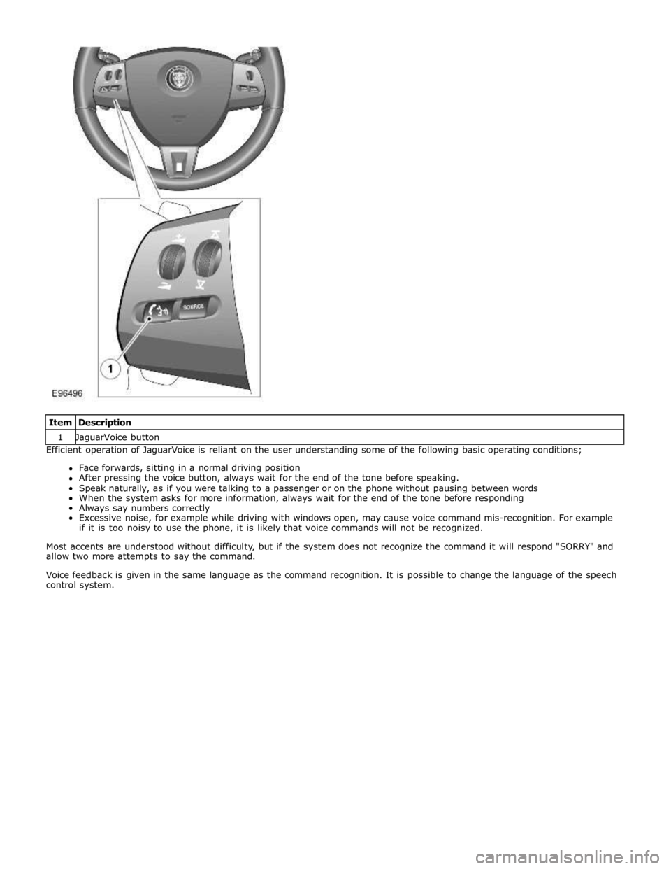
1 JaguarVoice button Efficient operation of JaguarVoice is reliant on the user understanding some of the following basic operating conditions;
Face forwards, sitting in a normal driving position
After pressing the voice button, always wait for the end of the tone before speaking.
Speak naturally, as if you were talking to a passenger or on the phone without pausing between words
When the system asks for more information, always wait for the end of the tone before responding
Always say numbers correctly
Excessive noise, for example while driving with windows open, may cause voice command mis-recognition. For example
if it is too noisy to use the phone, it is likely that voice commands will not be recognized.
Most accents are understood without difficulty, but if the system does not recognize the command it will respond "SORRY" and
allow two more attempts to say the command.
Voice feedback is given in the same language as the command recognition. It is possible to change the language of the speech
control system.
Page 2011 of 3039
Symptom Possible Cause Action
The connected iPOD® unit's
battery is not holding charge and
requires replacement
See diagnostic procedures as specified in pinpoint test A2
"Check The iPOD® Battery" below GO to Pinpoint Test A.
The iPOD® dock cable is not
securely installed
The iPOD® dock cable is faulty
See diagnostic procedures as specified in pinpoint test A3
"Check The iPOD® Is Charging When Connected To The
Audio Input Control Module" below GO to Pinpoint Test A. Symptom Chart - Intermittent Fault With Playback From USB Device
Symptom Possible Cause Action Intermittent fault
with USB
playback
The USB memory stick
is damaged or faulty
The USB memory stick
is incompatible with
the audio input control
module
Check for correct operation by connecting another working USB
memory stick loaded with a compatible test file (files may be
downloaded from Dension website). If fault clears, then the original
USB stick should be replaced. If problem persists, suspect a fault with
the USB extension cable
The USB extension
cable is not securely
installed
The USB extension
cable is faulty
See diagnostic procedures as specified in pinpoint test B3 "Check The
USB Extension Cable Is Operational And Securely Installed" below GO
to Pinpoint Test B.
The audio input control
module power harness
is not securely installed
The audio input control
module power harness
is faulty
Ensure all connectors of the audio input control module power harness
are correctly secured
If problem persists, check and install a new audio input control
module power harness Not all sound
files on the USB
are played
Sound files may be
saved in an
incompatible file format
Check that affected sound file is encoded in a compatible file format
- Compatible file formats: AAC (up to 320 kbit/s); MP3 (up to
320 kbit/s); MP3 variable bit rate (up to 320 kbit/s); WAV -
uncompressed files; OGG (up to 320 kbit/s); WMA - except
DRM protected files (up to 320 kbit/s)
Sound files may be
corrupted
Check integrity of affected files and remove any damaged files from
the memory stick Symptom Chart - No Response From CDC Button
Symptom Possible Cause Action No response
when the CDC
button is pressed
USB input or iPOD® input
faulty
First check operation of iPOD® playback. If iPOD® operates
normally but USB playback is faulty, then follow diagnostic
procedures as specified in pinpoint test B GO to Pinpoint Test B. If iPOD® playback is faulty but USB playback operates normally,
then follow diagnostic procedures as specified in pinpoint test A
GO to Pinpoint Test A.
The auxiliary input may be
switched to bypass mode
See diagnostic procedures as specified in pinpoint test A5:
"Check If The Bypass Switch On The Auxiliary Input Unit Is
Activated" below GO to Pinpoint Test A.
The audio input control
module power harness is not
securely installed
The audio input control
module power
supply/harness is faulty
Ensure all connectors of the audio input control module power
harness are correctly secured
See diagnostic procedures as specified in pinpoint tests C1:
"Check The Integrity Of Power Supply From Vehicle" and C2:
"Check The Integrity And Operation Of The Audio Input Control
Module Power Harness" below GO to Pinpoint Test C.
Optical cables/connectors (if
fitted) are not securely
installed
Optical cables/connectors (if
fitted) are faulty
Ensure the optical cables are routed appropriately to avoid
pinching the cable and with no excessive bends or kinks. Ensure
all connectors of the optical cables are correctly secured. Replace
any damaged or faulty optical cables and/or connectors as
required
If no CD changer is fitted, ensure that the optical cables are
configured in a closed loop so that the optical circuit is intact
Page 2015 of 3039
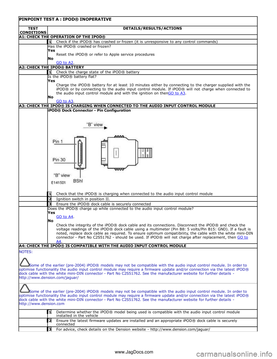
PINPOINT TEST A : IPOD® INOPERATIVE TEST
CONDITIONS DETAILS/RESULTS/ACTIONS A1: CHECK THE OPERATION OF THE IPOD® 1 Check if the iPOD® has crashed or frozen (it is unresponsive to any control commands) Has the iPOD® crashed or frozen?
Yes
Reset the iPOD® or refer to Apple service procedures
No
GO to A2. A2: CHECK THE IPOD® BATTERY 1 Check the charge state of the iPOD® battery Is the iPOD® battery flat?
Yes
Charge the iPOD® battery for at least 10 minutes either by connecting to the charger supplied with the
iPOD® or by connecting to the audio input control module. If iPOD® will not charge when connected to
the audio input control module and with the ignition on thenGO to A3. No
GO to A3. A3: CHECK THE IPOD® IS CHARGING WHEN CONNECTED TO THE AUDIO INPUT CONTROL MODULE iPOD® Dock Connector - Pin Configuration
1 Check that the iPOD® is charging when connected to the audio input control module 2 Ignition switch in position II. 3 Ensure the iPOD® dock cable is securely connected Does the iPOD® charge up while connected to the audio input control module?
Yes
GO to A4. No
Check the integrity of the iPOD® dock cable and its connections. Disconnect the iPOD® and check the
voltage readings of the iPOD® dock cable using a multimeter (Pin B8: 5 volts/Pin B15: GND). If a fault is
noted, replace dock cable as required. To ensure optimum compatibility, the cable with the white mini-DIN
connector - Part No C2S51762 - should be used. If iPOD® will not charge after replacement, then GO to A4. A4: CHECK THE IPOD® IS COMPATIBLE WITH THE AUDIO INPUT CONTROL MODULE NOTES:
Some of the earlier (pre-2004) iPOD® models may not be compatible with the audio input control module. In order to
optimise functionality the audio input control module may require a firmware update and/or connection via the latest iPOD®
dock cable with the white mini-DIN connector - Part No C2S51762. See the manufacturer website for further details -
http://www.dension.com/jaguar/
Some of the earlier (pre-2004) iPOD® models may not be compatible with the audio input control module. In order to
optimise functionality the audio input control module may require a firmware update and/or connection via the latest iPOD®
dock cable with the white mini-DIN connector - Part No C2S51762. See the manufacturer website for further details -
http://www.dension.com 1 Determine whether the iPOD® model being used is compatible with the audio input control module installed in the vehicle 2 Ensure the latest firmware updates are installed and an appropriate iPOD® dock cable is securely connected 3 For advice, check details on the Dension website - http://www.dension.com/jaguar/ www.JagDocs.com
Page 2022 of 3039
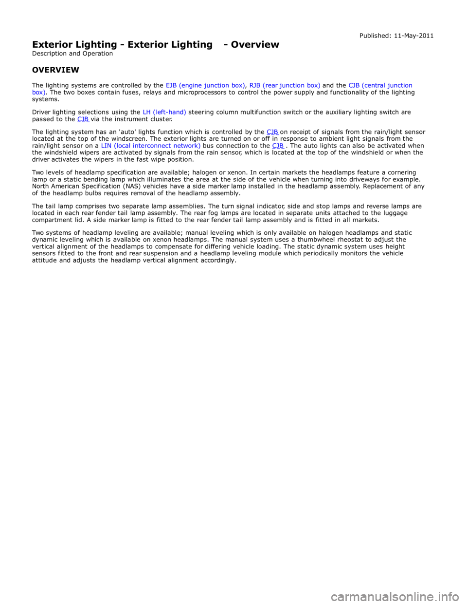
The lighting system has an 'auto' lights function which is controlled by the CJB on receipt of signals from the rain/light sensor located at the top of the windscreen. The exterior lights are turned on or off in response to ambient light signals from the
rain/light sensor on a LIN (local interconnect network) bus connection to the CJB . The auto lights can also be activated when the windshield wipers are activated by signals from the rain sensor, which is located at the top of the windshield or when the
driver activates the wipers in the fast wipe position.
Two levels of headlamp specification are available; halogen or xenon. In certain markets the headlamps feature a cornering
lamp or a static bending lamp which illuminates the area at the side of the vehicle when turning into driveways for example.
North American Specification (NAS) vehicles have a side marker lamp installed in the headlamp assembly. Replacement of any
of the headlamp bulbs requires removal of the headlamp assembly.
The tail lamp comprises two separate lamp assemblies. The turn signal indicator, side and stop lamps and reverse lamps are
located in each rear fender tail lamp assembly. The rear fog lamps are located in separate units attached to the luggage
compartment lid. A side marker lamp is fitted to the rear fender tail lamp assembly and is fitted in all markets.
Two systems of headlamp leveling are available; manual leveling which is only available on halogen headlamps and static
dynamic leveling which is available on xenon headlamps. The manual system uses a thumbwheel rheostat to adjust the
vertical alignment of the headlamps to compensate for differing vehicle loading. The static dynamic system uses height
sensors fitted to the front and rear suspension and a headlamp leveling module which periodically monitors the vehicle
attitude and adjusts the headlamp vertical alignment accordingly.
Page 2026 of 3039
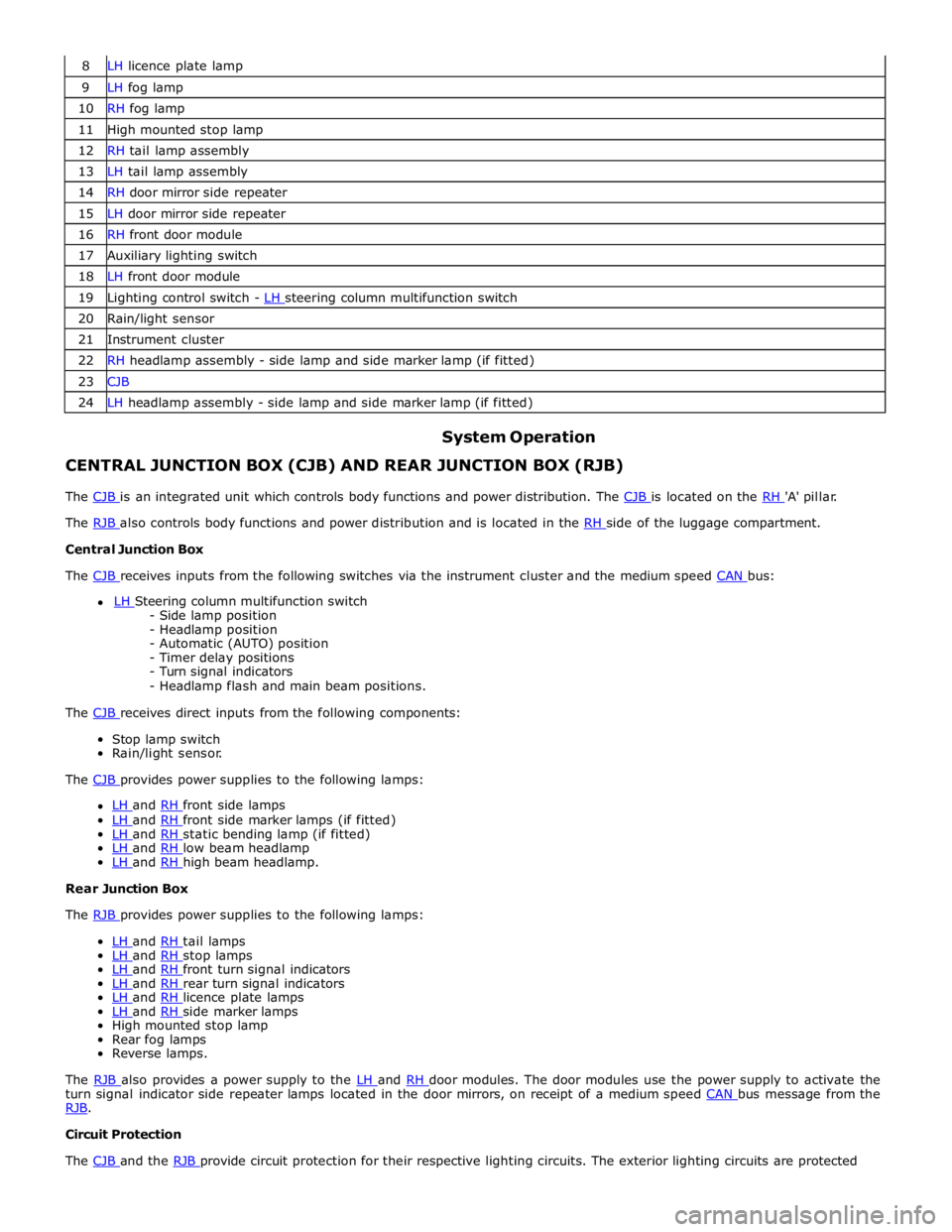
8 LH licence plate lamp 9 LH fog lamp 10 RH fog lamp 11 High mounted stop lamp 12 RH tail lamp assembly 13 LH tail lamp assembly 14 RH door mirror side repeater 15 LH door mirror side repeater 16 RH front door module 17 Auxiliary lighting switch 18 LH front door module 19 Lighting control switch - LH steering column multifunction switch 20 Rain/light sensor 21 Instrument cluster 22 RH headlamp assembly - side lamp and side marker lamp (if fitted) 23 CJB 24 LH headlamp assembly - side lamp and side marker lamp (if fitted)
System Operation CENTRAL JUNCTION BOX (CJB) AND REAR JUNCTION BOX (RJB)
The CJB is an integrated unit which controls body functions and power distribution. The CJB is located on the RH 'A' pillar. The RJB also controls body functions and power distribution and is located in the RH side of the luggage compartment. Central Junction Box
The CJB receives inputs from the following switches via the instrument cluster and the medium speed CAN bus: LH Steering column multifunction switch - Side lamp position
- Headlamp position
- Automatic (AUTO) position
- Timer delay positions
- Turn signal indicators
- Headlamp flash and main beam positions.
The CJB receives direct inputs from the following components: Stop lamp switch
Rain/light sensor.
The CJB provides power supplies to the following lamps:
LH and RH front side lamps LH and RH front side marker lamps (if fitted) LH and RH static bending lamp (if fitted) LH and RH low beam headlamp LH and RH high beam headlamp. Rear Junction Box
The RJB provides power supplies to the following lamps:
LH and RH tail lamps LH and RH stop lamps LH and RH front turn signal indicators LH and RH rear turn signal indicators LH and RH licence plate lamps LH and RH side marker lamps High mounted stop lamp
Rear fog lamps
Reverse lamps.
The RJB also provides a power supply to the LH and RH door modules. The door modules use the power supply to activate the turn signal indicator side repeater lamps located in the door mirrors, on receipt of a medium speed CAN bus message from the RJB. Circuit Protection
The CJB and the RJB provide circuit protection for their respective lighting circuits. The exterior lighting circuits are protected
Page 2027 of 3039
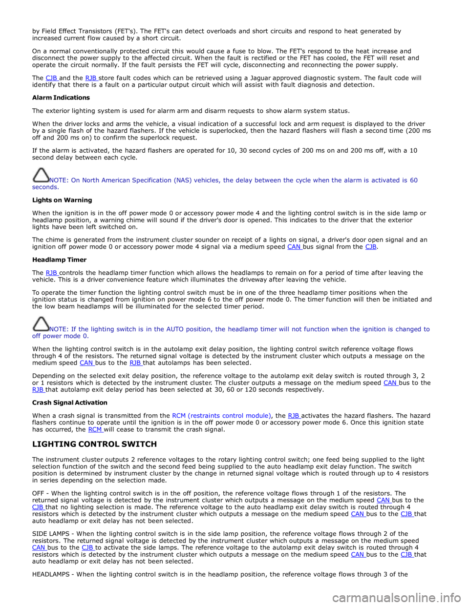
by Field Effect Transistors (FET's). The FET's can detect overloads and short circuits and respond to heat generated by
increased current flow caused by a short circuit.
On a normal conventionally protected circuit this would cause a fuse to blow. The FET's respond to the heat increase and
disconnect the power supply to the affected circuit. When the fault is rectified or the FET has cooled, the FET will reset and
operate the circuit normally. If the fault persists the FET will cycle, disconnecting and reconnecting the power supply.
The CJB and the RJB store fault codes which can be retrieved using a Jaguar approved diagnostic system. The fault code will identify that there is a fault on a particular output circuit which will assist with fault diagnosis and detection.
Alarm Indications
The exterior lighting system is used for alarm arm and disarm requests to show alarm system status.
When the driver locks and arms the vehicle, a visual indication of a successful lock and arm request is displayed to the driver
by a single flash of the hazard flashers. If the vehicle is superlocked, then the hazard flashers will flash a second time (200 ms
off and 200 ms on) to confirm the superlock request.
If the alarm is activated, the hazard flashers are operated for 10, 30 second cycles of 200 ms on and 200 ms off, with a 10
second delay between each cycle.
NOTE: On North American Specification (NAS) vehicles, the delay between the cycle when the alarm is activated is 60
seconds.
Lights on Warning
When the ignition is in the off power mode 0 or accessory power mode 4 and the lighting control switch is in the side lamp or
headlamp position, a warning chime will sound if the driver's door is opened. This indicates to the driver that the exterior
lights have been left switched on.
The chime is generated from the instrument cluster sounder on receipt of a lights on signal, a driver's door open signal and an
ignition off power mode 0 or accessory power mode 4 signal via a medium speed CAN bus signal from the CJB. Headlamp Timer
The RJB controls the headlamp timer function which allows the headlamps to remain on for a period of time after leaving the vehicle. This is a driver convenience feature which illuminates the driveway after leaving the vehicle.
To operate the timer function the lighting control switch must be in one of the three headlamp timer positions when the
ignition status is changed from ignition on power mode 6 to the off power mode 0. The timer function will then be initiated and
the low beam headlamps will be illuminated for the selected timer period.
NOTE: If the lighting switch is in the AUTO position, the headlamp timer will not function when the ignition is changed to
off power mode 0.
When the lighting control switch is in the autolamp exit delay position, the lighting control switch reference voltage flows
through 4 of the resistors. The returned signal voltage is detected by the instrument cluster which outputs a message on the
medium speed CAN bus to the RJB that autolamps has been selected.
Depending on the selected exit delay position, the reference voltage to the autolamp exit delay switch is routed through 3, 2
or 1 resistors which is detected by the instrument cluster. The cluster outputs a message on the medium speed CAN bus to the RJB that autolamp exit delay period has been selected at 30, 60 or 120 seconds respectively. Crash Signal Activation
When a crash signal is transmitted from the RCM (restraints control module), the RJB activates the hazard flashers. The hazard flashers continue to operate until the ignition is in the off power mode 0 or accessory power mode 6. Once this ignition state
has occurred, the RCM will cease to transmit the crash signal.
LIGHTING CONTROL SWITCH
The instrument cluster outputs 2 reference voltages to the rotary lighting control switch; one feed being supplied to the light
selection function of the switch and the second feed being supplied to the auto headlamp exit delay function. The switch
position is determined by instrument cluster by the change in returned signal voltage which is routed through up to 4 resistors
in series depending on the selection made.
OFF - When the lighting control switch is in the off position, the reference voltage flows through 1 of the resistors. The
returned signal voltage is detected by the instrument cluster which outputs a message on the medium speed CAN bus to the CJB that no lighting selection is made. The reference voltage to the auto headlamp exit delay switch is routed through 4 resistors which is detected by the instrument cluster which outputs a message on the medium speed CAN bus to the CJB that auto headlamp or exit delay has not been selected.
SIDE LAMPS - When the lighting control switch is in the side lamp position, the reference voltage flows through 2 of the
resistors. The returned signal voltage is detected by the instrument cluster which outputs a message on the medium speed
CAN bus to the CJB to activate the side lamps. The reference voltage to the autolamp exit delay switch is routed through 4 resistors which is detected by the instrument cluster which outputs a message on the medium speed CAN bus to the CJB that auto headlamp or exit delay has not been selected.
HEADLAMPS - When the lighting control switch is in the headlamp position, the reference voltage flows through 3 of the