2010 JAGUAR XFR turn signal bulb
[x] Cancel search: turn signal bulbPage 1367 of 3039
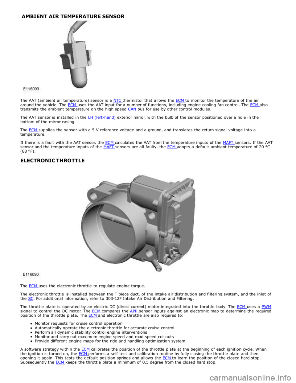
around the vehicle. The ECM uses the AAT input for a number of functions, including engine cooling fan control. The ECM also transmits the ambient temperature on the high speed CAN bus for use by other control modules.
The AAT sensor is installed in the LH (left-hand) exterior mirror, with the bulb of the sensor positioned over a hole in the
bottom of the mirror casing.
The ECM supplies the sensor with a 5 V reference voltage and a ground, and translates the return signal voltage into a temperature.
If there is a fault with the AAT sensor, the ECM calculates the AAT from the temperature inputs of the MAFT sensors. If the AAT sensor and the temperature inputs of the MAFT sensors are all faulty, the ECM adopts a default ambient temperature of 20 °C (68 °F).
ELECTRONIC THROTTLE
The ECM uses the electronic throttle to regulate engine torque.
The electronic throttle is installed between the T piece duct, of the intake air distribution and filtering system, and the inlet of
the SC. For additional information, refer to 303-12F Intake Air Distribution and Filtering.
The throttle plate is operated by an electric DC (direct current) motor integrated into the throttle body. The ECM uses a PWM signal to control the DC motor. The ECM compares the APP sensor inputs against an electronic map to determine the required position of the throttle plate. The ECM and electronic throttle are also required to: Monitor requests for cruise control operation
Automatically operate the electronic throttle for accurate cruise control
Perform all dynamic stability control engine interventions
Monitor and carry out maximum engine speed and road speed cut outs
Provide different engine maps for the ride and handling optimization system.
A software strategy within the ECM calibrates the position of the throttle plate at the beginning of each ignition cycle. When the ignition is turned on, the ECM performs a self test and calibration routine by fully closing the throttle plate and then opening it again. This tests the default position springs and allows the ECM to learn the position of the closed hard stop. Subsequently the ECM keeps the throttle plate a minimum of 0.5 degree from the closed hard stop. AMBIENT AIR TEMPERATURE SENSOR
Page 1786 of 3039
6. Adaptive Speed Control Indicator
The adaptive speed control system is controlled by the adaptive speed control module. Operation of the SET +/- switches on
the steering wheel will activate the system. Operation of the switches is detected by the adaptive speed control module. The
module issues a high speed CAN message to the instrument cluster which illuminates the adaptive speed control indicator, when the system is in 'follow mode', in an amber color and displays a 'SETSPEED XXX MPH / KM/H' message in the message
center. The indicator is illuminated in an amber color for a 3 second indicator check when the ignition is switched on.
7. Anti-lock Braking System (ABS) Warning Indicator
The ABS warning indicator is controlled by the ABS module. If a fault in the ABS system is detected by the ABS module, the module issues a high speed CAN message to the instrument cluster to illuminate the ABS warning indicator in an amber color and display the message 'ABS FAULT' in the instrument cluster. The indicator is illuminated in an amber color for a 3 second
indicator check when the ignition is switched on. If a fault is present when the ignition is on, the bulb will remain illuminated
after the 3 second indicator check period.
NOTES:
The 'ABS FAULT' message is not displayed in NAS markets).
If both the ABS warning indicator and the brake warning indicator illuminate simultaneously, a major fault in the brake system will have occurred.
On NAS vehicles, the ABS warning indicator is also used for parking brake operation. The NAS warning indicator does not have 'ABS' on the icon and will function as described previously for the parking brake operation of the brake warning indicator.
8. Engine Malfunction Indicator Lamp (MIL)
The MIL warning indicator is controlled by the ECM and illuminated by the instrument cluster on receipt of a message on the high speed CAN bus from the ECM. The indicator is illuminated in an amber color for a 3 second indicator check when the ignition is switched on.
If the MIL remains illuminated after the engine is started or illuminates when driving, a fault is present and must be
investigated at the earliest opportunity. Illumination of the MIL warning indicator alerts the driver to an OBD (on-board
diagnostic) fault which will cause excessive emissions output. This may relate to either an engine management system fault or
a transmission.
9. Tire Pressure Monitoring System (TPMS) Warning Indicator
The TPMS warning indicator is illuminated by the instrument cluster on receipt of a medium speed CAN message from the TPMS module. The indicator is illuminated in an amber color for a 3 second indicator check when the ignition is switched on.
If the indicator illuminates and is accompanied by the message 'TYRE PRESSURE SYSTEM FAULT' in the message center, then a
TPMS fault has occurred. If the indicator illuminates and accompanied by a different message, then a low tire pressure has
been detected, a spare wheel has been fitted or a TPMS sensor has failed.
10. Airbag Warning Indicator
The airbag warning indicator is controlled by the instrument cluster. The indicator is illuminated in an amber color for the 3
second indicator check when the ignition is switched on. The indicator remains illuminated after the 3 second period has
expired until the instrument cluster receives a turn off message on the high speed CAN bus from the RCM (restraints control module).
11. Front Fog Lamp Indicator
The green colored front fog lamp indicator is controlled by the CJB and illuminated by the instrument cluster on receipt of a front fog lamp on message on the medium speed CAN bus from the CJB. The indicator is illuminated for as long as the front fog lamps are active. The front fog lamp indicator is not subject to the 3 second indicator check when the ignition is switched
on.
12. Dynamic Stability Control (DSC) Indicator
The DSC warning lamp is controlled by the ABS module and illuminated by the instrument cluster in response to messages received on the high speed CAN bus. The indicator is illuminated in an amber color for the 3 second indicator check when the ignition is switched on. The DSC warning indicator, are permanently illuminated in an amber color if the instrument cluster
receives a high speed CAN message from the ABS module relating to one of the following faults:
Traction control fault
Yaw control fault
Engine drag torque control fault
Panic Brake Assist (PBA) fault
Signal missing relating to either traction control active, yaw control active or DSC switch input.
The above faults will also generate an applicable DSC and ABS warning message in the message center. The DSC warning
indicator will flash at 2 Hz for if the traction control or yaw control is active when the DSC system is enabled. If the DSC
system is switched off, the warning indicator will be permanently illuminated until the DSC system is subsequently
re-activated.
13. Safety Belt Warning Indicator
The safety belt warning indicator operates for both the driver and passenger safety belts. The warning indicator is controlled by
Page 1828 of 3039
STEERING
COLUMN LOCKED Red warning triangle
illuminated in LCD. Fault has occurred preventing the
steering column lock from unlocking. This will also prevent the engine from
starting. Press the stop/start button to return to
accessory mode 4. If steering column
is still locked, investigate cause of
fault and interrogate the CJB (central junction box) for faults and diagnose
using an approved Jaguar Diagnostic System. IGNITION ON
Red warning triangle
illuminated in LCD. Stop/start button has been pressed
without the brake pedal depressed. Ignition is now in power mode 6. None ENGINE STOP
BUTTON PRESSED Red warning triangle
illuminated in LCD. Engine stop button has been pressed
when the vehicle is moving. Engine will
not be switched off until button is pressed quickly for a second time. Do not stop engine when vehicle is
moving unless necessary. LIGHTS ON
Amber warning triangle
illuminated in LCD. Side lamps or headlamps are on and the
driver's door has been opened. Switch off headlamps to avoid
excessive drain on battery. AUTOLAMP
DELAY OFF None
Autolamp delay feature has been
deactivated by moving light control
switch from the auto position. None AUTOLAMP
DELAY XX:XX None
Lighting control switch has been moved
to one of the 4 autolamp delay
positions. Message displays delay timer period selected. None AUTOLAMP
DELAY None
Autolamp delay is selected on the light
control switch and the driver has
switched off ignition and opened driver's
door initiating the autolamp delay. None. Message will extinguish once the
selected delay timer has switched off
the headlamps. TAIL LAMP
FAILURE None The tail lamp LED (light emitting
diode)'s are not functioning correctly.
Location shown on vehicle image. Correct fault in rear lamp assembly,
RJB (rear junction box) or wiring. BRAKE LAMP
FAILURE None The brake lamp LED's are not functioning correctly. Location shown on displayed vehicle image. Correct fault in rear lamp assembly,
RJB or wiring. INDICATOR LAMP
FAILURE None
A turn signal indicator bulb has failed.
Location is shown on displayed vehicle image. Replace failed turn signal indicator
bulb. E-DIFF NOT
AVAILABLE Amber warning triangle
illuminated in LCD accompanied with a single
chime Differential temperature has reached the
overheat threshold. System deactivated
until temperature returns within limits. Allow differential to cool. E-DIFF FAULT
Amber warning triangle
illuminated in LCD accompanied with a single
chime Fault has occurred with electronic
differential. System deactivated until
fault rectified. Investigate cause of fault and
interrogate the system for faults and
diagnose using an approved Jaguar Diagnostic System. ENGINE OIL LOW
Amber warning triangle
illuminated in LCD accompanied with a single
chime The oil is at the minimum level for safe
operation. Top-up with 1 liter (1.8 pints) of oil. ENGINE OIL
HIGH Amber warning triangle
illuminated in LCD accompanied with a single
chime This warning is displayed when the
engine is started, if the oil is above the
maximum level for safe operation. Stop the vehicle as soon as safety
permits and have the engine oil
drained to correct level, before driving
the vehicle. ENGINE OIL
CRITICALLY LOW Red warning triangle
illuminated LCD accompanied with a single
chime The oil is below the minimum level for
safe operation. Stop the vehicle as soon as safety
permits and top-up with 1.5 liters (2.6
pints) of oil. Wait for 10 minutes,
re-check the oil level reading and top-up again if necessary. ENGINE OIL
LEVEL MONITOR
SYSTEM FAULT Amber warning triangle
illuminated in LCD accompanied with a single
chime A fault with the oil level monitoring
system is indicated. Investigate cause of fault and
interrogate the ECM for faults and diagnose using an approved Jaguar Diagnostic System. WATER IN FUEL
Amber warning triangle
illuminated in LCD accompanied with a single
chime The water in fuel sensor in the fuel filter
has detected water in the fuel system. Drain fuel filter to remove collected
water. Odometer Display
The odometer displays the total distance which the vehicle has traveled. This is calculated by the instrument cluster using
wheel speed signals from the ABS module.
The odometer can show 6 characters and distances up to 999,999 miles or kilometers. The total distance travelled is stored in a
EEPROM (electrically erasable programmable read only memory) and the RAM (random access memory). This ensures that the
total distance is not lost if the battery is disconnected.
The odometer value is passed to other vehicle system modules on the medium speed and high speed CAN bus. This is used to record the total vehicle mileage for diagnostic purposes and when storing DTC (diagnostic trouble code)'s.
Page 2019 of 3039

Low beam headlamp bulb - Vehicles with conventional headlamps - non Federal H7 Low beam headlamp bulb - Vehicles with conventional headlamps - Federal H11 Low beam headlamp bulb - Vehicles with xenon headlamps D1S High beam headlamp bulb H7 Cornering lamp bulb H8 Side repeater lamp bulb WY5W Side marker lamp bulb - Federal W5W Front turn signal lamp bulb - non Federal PY21W Front turn signal lamp bulb - Federal 3457 AK Rear turn signal lamp bulb PY19W Front side/parking lamp bulb - Vehicles built up to 01/2009 W5W halogen cool blue Front side/parking lamp bulb - Vehicles built 02/2009 onwards W5W Reversing lamp bulb PS19W
Page 2022 of 3039
The lighting system has an 'auto' lights function which is controlled by the CJB on receipt of signals from the rain/light sensor located at the top of the windscreen. The exterior lights are turned on or off in response to ambient light signals from the
rain/light sensor on a LIN (local interconnect network) bus connection to the CJB . The auto lights can also be activated when the windshield wipers are activated by signals from the rain sensor, which is located at the top of the windshield or when the
driver activates the wipers in the fast wipe position.
Two levels of headlamp specification are available; halogen or xenon. In certain markets the headlamps feature a cornering
lamp or a static bending lamp which illuminates the area at the side of the vehicle when turning into driveways for example.
North American Specification (NAS) vehicles have a side marker lamp installed in the headlamp assembly. Replacement of any
of the headlamp bulbs requires removal of the headlamp assembly.
The tail lamp comprises two separate lamp assemblies. The turn signal indicator, side and stop lamps and reverse lamps are
located in each rear fender tail lamp assembly. The rear fog lamps are located in separate units attached to the luggage
compartment lid. A side marker lamp is fitted to the rear fender tail lamp assembly and is fitted in all markets.
Two systems of headlamp leveling are available; manual leveling which is only available on halogen headlamps and static
dynamic leveling which is available on xenon headlamps. The manual system uses a thumbwheel rheostat to adjust the
vertical alignment of the headlamps to compensate for differing vehicle loading. The static dynamic system uses height
sensors fitted to the front and rear suspension and a headlamp leveling module which periodically monitors the vehicle
attitude and adjusts the headlamp vertical alignment accordingly.
Page 2028 of 3039
resistors. The returned signal voltage is detected by the instrument cluster which outputs a message on the medium speed
CAN bus to the CJB to activate the headlamps. The reference voltage to the auto headlamp exit delay switch is routed through 4 resistors which is detected by the instrument cluster which outputs a message on the medium speed CAN bus to the CJB that auto headlamp or exit delay has not been selected.
AUTOLAMPS - When the lighting control switch is in the auto headlamp position, the reference voltage flows through 4 of the
resistors. The returned signal voltage is detected by the instrument cluster which outputs a message on the medium speed
CAN bus to the CJB to activate the autolamp function. The reference voltage to the autolamp exit delay switch is routed through 4 resistors which is detected by the instrument cluster which outputs a message on the medium speed CAN bus to the CJB that auto headlamp has been selected.
AUXILIARY LIGHTING SWITCH
Headlamp Leveling Rotary Thumbwheel (Halogen headlamps only)
A power supply is passed to the headlamp leveling thumbwheel from the ignition relay in the EJB. Depending on the position of the thumbwheel, the voltage passes through 1, 2 or 3 resistors connected in series. The voltage through the resistors is
passed to the headlamp leveling motor controller in each headlamp. The received voltage is determined as a request for the
appropriate level position and the controller powers the headlamp level motors to the applicable position for each headlamp.
Rear Fog Lamp Switch
The instrument cluster supplies a reference voltage and return to the rear fog lamp switch. The fog lamp switch is a
non-latching, momentary switch.
When the fog lamp switch is off the reference voltage is passed through a 1Kohm resistor. The voltage through the resistor is
returned to the instrument cluster that determines that no request for fog lamp operation has been made.
When the driver presses the fog lamp switch, the reference voltage is passed through a 330 ohm resistor. The change is return
voltage is sensed by the instrument cluster which determines fog lamp operation has been requested. The instrument cluster
transmits a medium speed CAN bus signal to the RJB providing the lighting control switch is in the correct position. The RJB reacts to the message and provides a power supply to the 3 LED (light emitting diode)'s in each rear fog lamp. A fog lamp
warning lamp in the instrument cluster will also be illuminated when the fog lamps are operating.
The RJB will only activate the rear fog lamps if the headlamps are selected on or are active with auto headlamp activation. When the headlamps are turned off the fog lamps are also turned off. When the headlamps are next switched on, the fog
lamps will not be activated until the driver requests fog lamp operation.
NOTE: The fog lamps do operate when DRL (daytime running lamps) are active.
HEADLAMP LEVELING
Manual Headlamp Leveling - Halogen headlamps only
A power supply is passed to the headlamp leveling motor in each headlamp from the ignition relay in the EJB. When a signal voltage is received from the headlamp leveling rotary thumbwheel, the headlamp leveling motor controller in each headlamp
uses the power supply to operate the motors and move the headlamp to the requested position.
Static Dynamic Headlamp Leveling - Xenon headlamps only
The headlamp leveling module receives a power supply from the ignition relay in the EJB. The same power supply is also supplied to the headlamp leveling motor in each headlamp assembly. The front and rear height sensors are connected to the
headlamp leveling module and receive a power and ground from the module. Each sensor has a signal line to the headlamp
leveling module to return height information to the module. The module uses the height signals from the sensors to calculate
the vehicle attitude and supplies a signal to each motor to power the headlamp to the required position.
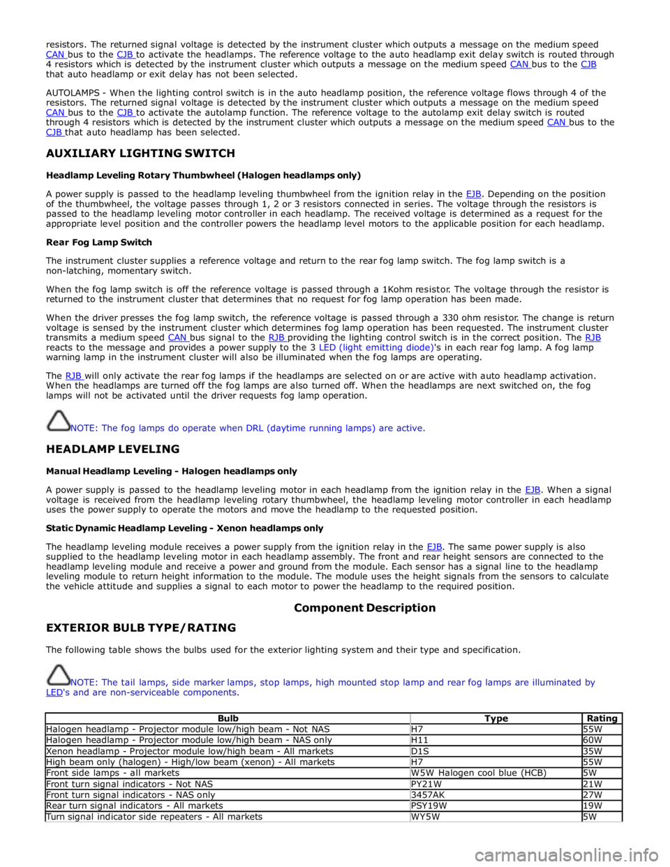
EXTERIOR BULB TYPE/RATING Component Description
The following table shows the bulbs used for the exterior lighting system and their type and specification.
NOTE: The tail lamps, side marker lamps, stop lamps, high mounted stop lamp and rear fog lamps are illuminated by
LED's and are non-serviceable components.
Bulb Type Rating Halogen headlamp - Projector module low/high beam - Not NAS H7 55W Halogen headlamp - Projector module low/high beam - NAS only H11 60W Xenon headlamp - Projector module low/high beam - All markets D1S 35W High beam only (halogen) - High/low beam (xenon) - All markets H7 55W Front side lamps - all markets W5W Halogen cool blue (HCB) 5W Front turn signal indicators - Not NAS PY21W 21W Front turn signal indicators - NAS only 3457AK 27W Rear turn signal indicators - All markets PSY19W 19W Turn signal indicator side repeaters - All markets WY5W 5W
Page 2029 of 3039
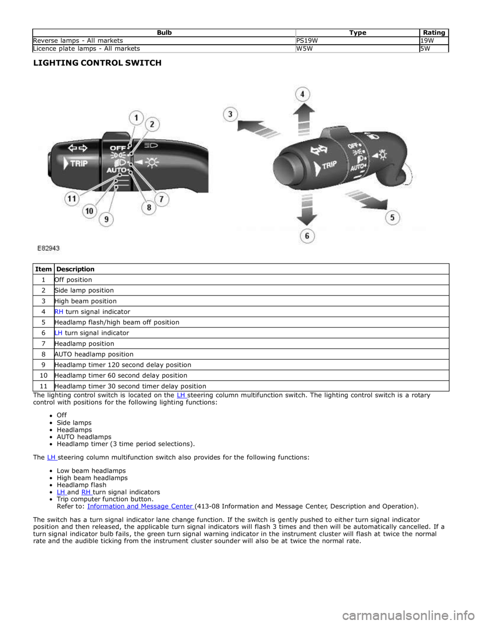
Bulb Type Rating Reverse lamps - All markets PS19W 19W Licence plate lamps - All markets W5W 5W LIGHTING CONTROL SWITCH
Item Description 1 Off position 2 Side lamp position 3 High beam position 4 RH turn signal indicator 5 Headlamp flash/high beam off position 6 LH turn signal indicator 7 Headlamp position 8 AUTO headlamp position 9 Headlamp timer 120 second delay position 10 Headlamp timer 60 second delay position 11 Headlamp timer 30 second timer delay position The lighting control switch is located on the LH steering column multifunction switch. The lighting control switch is a rotary control with positions for the following lighting functions:
Off
Side lamps
Headlamps
AUTO headlamps
Headlamp timer (3 time period selections).
The LH steering column multifunction switch also provides for the following functions: Low beam headlamps
High beam headlamps
Headlamp flash
LH and RH turn signal indicators Trip computer function button.
Refer to: Information and Message Center (413-08 Information and Message Center, Description and Operation).
The switch has a turn signal indicator lane change function. If the switch is gently pushed to either turn signal indicator
position and then released, the applicable turn signal indicators will flash 3 times and then will be automatically cancelled. If a
turn signal indicator bulb fails, the green turn signal warning indicator in the instrument cluster will flash at twice the normal
rate and the audible ticking from the instrument cluster sounder will also be at twice the normal rate.
Page 2030 of 3039
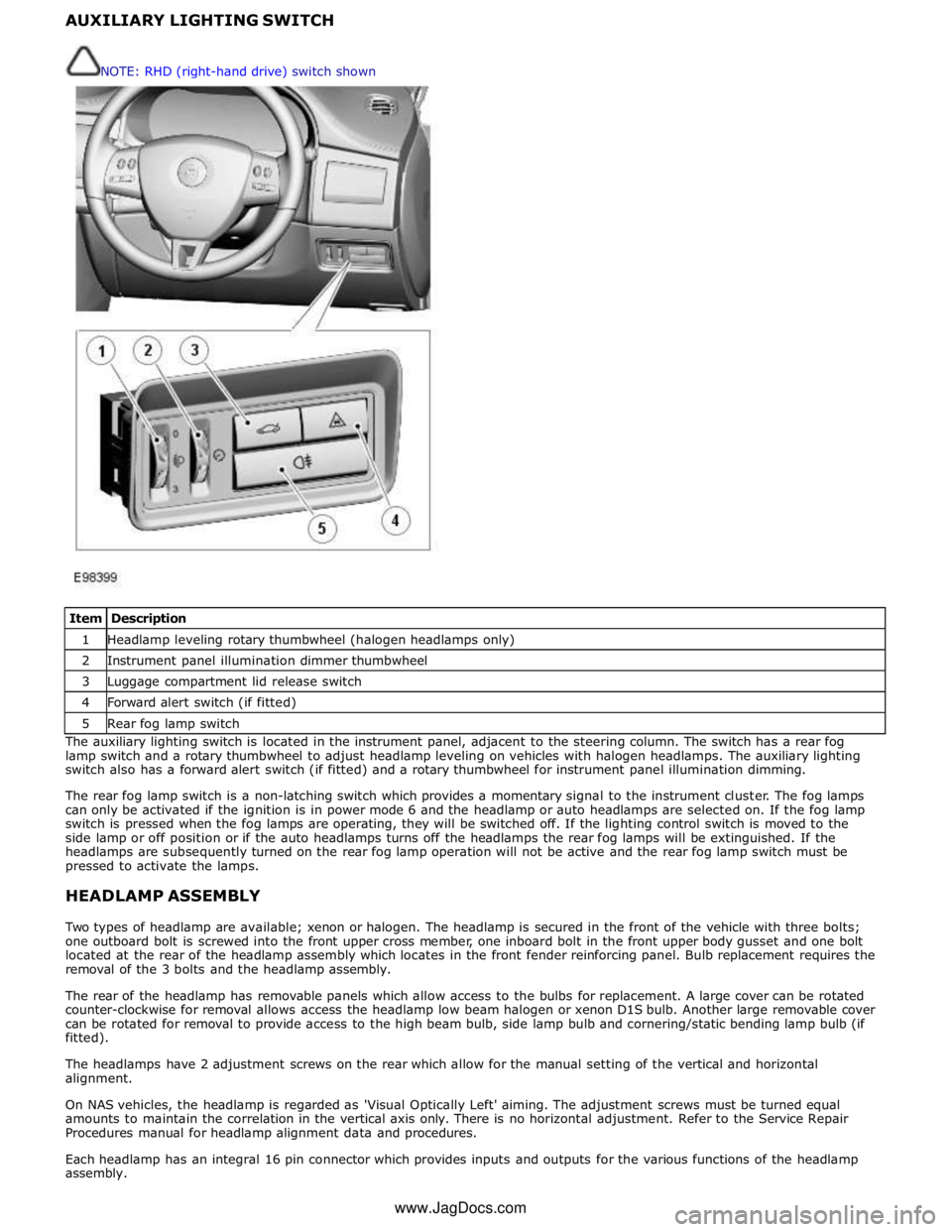
1 Headlamp leveling rotary thumbwheel (halogen headlamps only) 2 Instrument panel illumination dimmer thumbwheel 3 Luggage compartment lid release switch 4 Forward alert switch (if fitted) 5 Rear fog lamp switch The auxiliary lighting switch is located in the instrument panel, adjacent to the steering column. The switch has a rear fog
lamp switch and a rotary thumbwheel to adjust headlamp leveling on vehicles with halogen headlamps. The auxiliary lighting
switch also has a forward alert switch (if fitted) and a rotary thumbwheel for instrument panel illumination dimming.
The rear fog lamp switch is a non-latching switch which provides a momentary signal to the instrument cluster. The fog lamps
can only be activated if the ignition is in power mode 6 and the headlamp or auto headlamps are selected on. If the fog lamp
switch is pressed when the fog lamps are operating, they will be switched off. If the lighting control switch is moved to the
side lamp or off position or if the auto headlamps turns off the headlamps the rear fog lamps will be extinguished. If the
headlamps are subsequently turned on the rear fog lamp operation will not be active and the rear fog lamp switch must be
pressed to activate the lamps.
HEADLAMP ASSEMBLY
Two types of headlamp are available; xenon or halogen. The headlamp is secured in the front of the vehicle with three bolts;
one outboard bolt is screwed into the front upper cross member, one inboard bolt in the front upper body gusset and one bolt
located at the rear of the headlamp assembly which locates in the front fender reinforcing panel. Bulb replacement requires the
removal of the 3 bolts and the headlamp assembly.
The rear of the headlamp has removable panels which allow access to the bulbs for replacement. A large cover can be rotated
counter-clockwise for removal allows access the headlamp low beam halogen or xenon D1S bulb. Another large removable cover
can be rotated for removal to provide access to the high beam bulb, side lamp bulb and cornering/static bending lamp bulb (if
fitted).
The headlamps have 2 adjustment screws on the rear which allow for the manual setting of the vertical and horizontal
alignment.
On NAS vehicles, the headlamp is regarded as 'Visual Optically Left' aiming. The adjustment screws must be turned equal
amounts to maintain the correlation in the vertical axis only. There is no horizontal adjustment. Refer to the Service Repair
Procedures manual for headlamp alignment data and procedures.
Each headlamp has an integral 16 pin connector which provides inputs and outputs for the various functions of the headlamp
assembly. NOTE: RHD (right-hand drive) switch shown
www.JagDocs.com