2010 Hyundai Genesis Coupe turn signal
[x] Cancel search: turn signalPage 12 of 322

15
Introduction
INDICATOR SYMBOLS ON THE INSTRUMENT CLUSTER
Seat belt warning light
High beam indicator
Turn signal indicator
ABS warning light
Parking brake & Brake fluid
warning light
Engine oil pressure warning light
ESP indicator (if equipped)
ESP OFF indicator (if equipped)
Malfunction indicator light
Air bag warning light
Cruise indicator (if equipped)
Cruise SET indicator (if equipped)
Immobilizer indicator (if equipped)
Low fuel level warning light
* For more detailed explanations, refer to “Instrument cluster” in section 4.
Charging system warning light
Low windshield washer fluid
level warning light (if equipped)
A050000ABK-EE
Door ajar warning light
Overspeed warning light (if equipped)
120km/h
Key out warning (if equipped) KEY
OUT
Trunk ajar warning light
Front fog light indicator (if equipped)
Tail light indicator (if equipped)
Page 14 of 322

Your vehicle at a glance
2
2
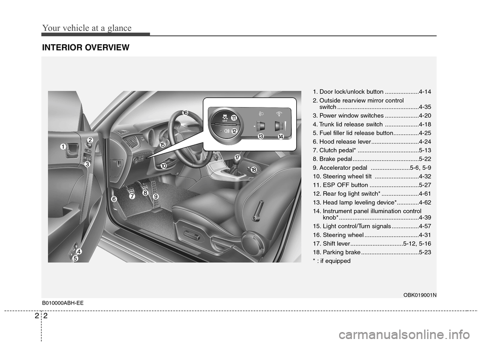
INTERIOR OVERVIEW
1. Door lock/unlock button ....................4-14
2. Outside rearview mirror control
switch ................................................4-35
3. Power window switches ....................4-20
4. Trunk lid release switch ....................4-18
5. Fuel filler lid release button...............4-25
6. Hood release lever ............................4-24
7. Clutch pedal* ....................................5-13
8. Brake pedal .......................................5-22
9. Accelerator pedal .......................5-6, 5-9
10. Steering wheel tilt ..........................4-32
11. ESP OFF button .............................5-27
12. Rear fog light switch* ......................4-61
13. Head lamp leveling device*.............4-62
14. Instrument panel illumination control knob* ...............................................4-39
15. Light control/Turn signals ................4-57
16. Steering wheel ................................4-31
17. Shift lever ...............................5-12, 5-16
18. Parking brake ..................................5-23
* : if equipped
OBK019001N
B010000ABH-EE
Page 51 of 322

Safety features of your vehicle
34
3
C040900AEN
How does the air bag system operate
Air bags are activated (able to inflate if
necessary) only when the ignition
switch is turned to the ON or STARTposition.
Air bags inflate instantly in the event of a serious frontal or side collision (ifequipped with side impact air bag or
curtain air bag) in order to help protect
the occupants from serious physical
injury.
There is no single speed at which the air bags will inflate.
Generally, air bags are designed to
inflate based upon the severity of a col-
lision and its direction. These two fac-
tors determine whether the sensors
produce an electronic deployment/inflation signal.
Air bag deployment depends on a number of factors including vehiclespeed, angles of impact and the densi-
ty and stiffness of the vehicles or
objects which your vehicle hits in the
collision. The determining factors are
not limited to those mentioned above.
The front air bags will completely inflate and deflate in an instant.
It is virtually impossible for you to see
the air bags inflate during an accident. It is much more likely that you will sim-ply see the deflated air bags hanging
out of their storage compartments afterthe collision.
In order to help provide protection in a severe collision, the air bags must
inflate rapidly. The speed of air baginflation is a consequence of the
extremely short time in which a collisionoccurs and the need to inflate the air
bag between the occupant and the
vehicle structures before the occupant
impacts those structures. This speed of
inflation reduces the risk of serious or
life-threatening injuries in a severe col-
lision and is thus a necessary part of airbag design.
However, air bag inflation can also
cause injuries which can include facial
abrasions, bruises and broken bonesbecause the inflation speed also caus-
es the air bags to expand with a great
deal of force.
There are even circumstances under which contact with the steer-
ing wheel air bag can cause fatal
injuries, especially if the occupant
is positioned excessively close tothe steering wheel.
WARNING
To avoid severe personal injury or death caused by deploying air
bags in a collision, the driver
should sit as far back from the
steering wheel air bag as possi-
ble (at least 250 mm (10 inches)
away). The front passengers
should always move their seats
as far back as possible and sit
back in their seat.
Air bags inflate instantly in the event of collision, and passen-
gers may be injured by the air bag
expansion force if they are not in
proper position.
Air bag inflation may cause injuries including facial or bodily
abrasions, injuries from broken
glasses or burns.
Page 102 of 322

Safety features of your vehicle
34
3
C040900AEN
How does the air bag system operate
Air bags are activated (able to inflate if
necessary) only when the ignition
switch is turned to the ON or STARTposition.
Air bags inflate instantly in the event of a serious frontal or side collision (ifequipped with side impact air bag or
curtain air bag) in order to help protect
the occupants from serious physical
injury.
There is no single speed at which the air bags will inflate.
Generally, air bags are designed to
inflate based upon the severity of a col-
lision and its direction. These two fac-
tors determine whether the sensors
produce an electronic deployment/inflation signal.
Air bag deployment depends on a number of factors including vehiclespeed, angles of impact and the densi-
ty and stiffness of the vehicles or
objects which your vehicle hits in the
collision. The determining factors are
not limited to those mentioned above.
The front air bags will completely inflate and deflate in an instant.
It is virtually impossible for you to see
the air bags inflate during an accident. It is much more likely that you will sim-ply see the deflated air bags hanging
out of their storage compartments afterthe collision.
In order to help provide protection in a severe collision, the air bags must
inflate rapidly. The speed of air baginflation is a consequence of the
extremely short time in which a collisionoccurs and the need to inflate the air
bag between the occupant and the
vehicle structures before the occupant
impacts those structures. This speed of
inflation reduces the risk of serious or
life-threatening injuries in a severe col-
lision and is thus a necessary part of airbag design.
However, air bag inflation can also
cause injuries which can include facial
abrasions, bruises and broken bonesbecause the inflation speed also caus-
es the air bags to expand with a great
deal of force.
There are even circumstances under which contact with the steer-
ing wheel air bag can cause fatal
injuries, especially if the occupant
is positioned excessively close tothe steering wheel.
WARNING
To avoid severe personal injury or death caused by deploying air
bags in a collision, the driver
should sit as far back from the
steering wheel air bag as possi-
ble (at least 250 mm (10 inches)
away). The front passengers
should always move their seats
as far back as possible and sit
back in their seat.
Air bags inflate instantly in the event of collision, and passen-
gers may be injured by the air bag
expansion force if they are not in
proper position.
Air bag inflation may cause injuries including facial or bodily
abrasions, injuries from broken
glasses or burns.
Page 149 of 322

497
Features of your vehicle
AUDIO SYSTEM
D281400AFD
Aux, USB and iPod port (if equipped)
If your vehicle has an aux and/or
USB(universal serial bus) port or iPod
port, you can use an aux port to connect
audio devices a USB port to plug in a
USB, and an iPod port to plug in an iPod.
✽✽ NOTICE
When using a portable audio device
connected to the power outlet, noise may
occur during playback. If this happens,
use the power source of the portable
audio device.
D300102ABH Glass antenna (if equipped)
When the radio power switch is turned on
while the ignition switch is in either the
“ON” or “ACC” position, your car will
receive both AM and FM broadcast sig-nals through the antenna in the rear win-
dow glass.
OBK049090
CAUTION
• Do not clean the inside of the rear window glass with a cleaner or
use a scraper to remove foreign deposits as this may cause dam-age to the antenna elements.
Avoid adding metallic coating (such as Ni, Cd, and so on). Thesecan disturb receiving broadcastsignals.
OBK049092
Page 226 of 322

What to do in an emergency
2
6
ROAD WARNING
F010100AUN
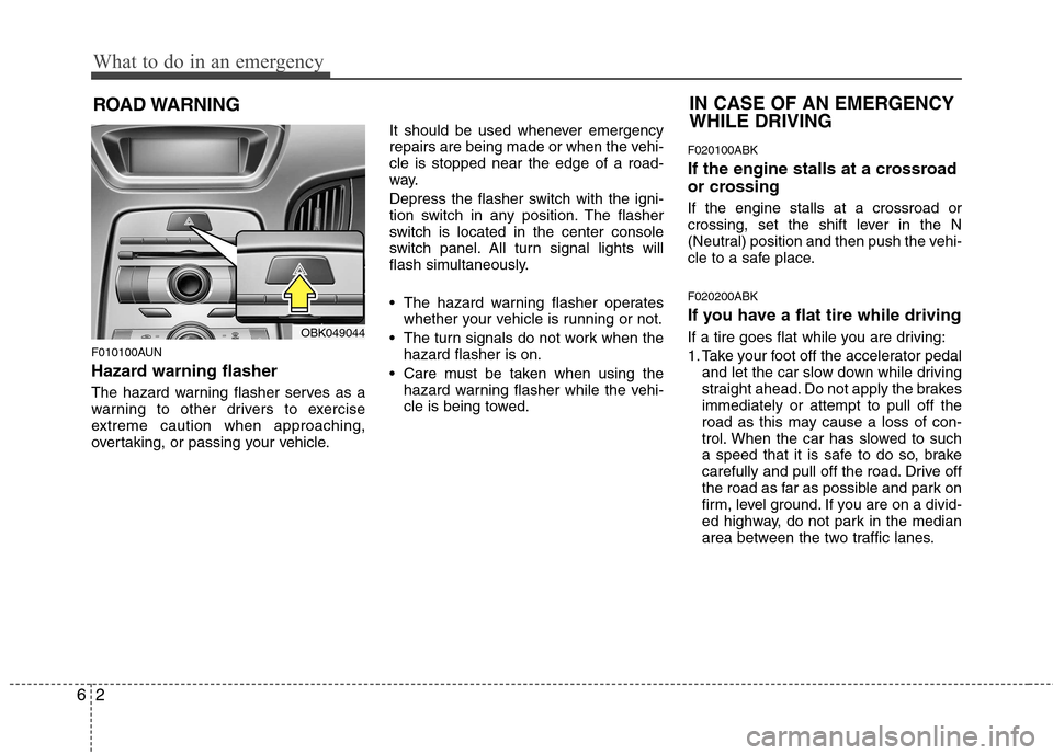
Hazard warning flasher
The hazard warning flasher serves as a
warning to other drivers to exercise
extreme caution when approaching,
overtaking, or passing your vehicle. It should be used whenever emergency
repairs are being made or when the vehi-cle is stopped near the edge of a road-
way.
Depress the flasher switch with the igni-
tion switch in any position. The flasher
switch is located in the center console
switch panel. All turn signal lights will
flash simultaneously.
• The hazard warning flasher operates
whether your vehicle is running or not.
The turn signals do not work when the hazard flasher is on.
Care must be taken when using the hazard warning flasher while the vehi-
cle is being towed. F020100ABK
If the engine stalls at a crossroad
or crossing If the engine stalls at a crossroad or
crossing, set the shift lever in the N
(Neutral) position and then push the vehi-
cle to a safe place. F020200ABK
If you have a flat tire while driving
If a tire goes flat while you are driving:
1. Take your foot off the accelerator pedal
and let the car slow down while driving
straight ahead. Do not apply the brakesimmediately or attempt to pull off the
road as this may cause a loss of con-
trol. When the car has slowed to such
a speed that it is safe to do so, brake
carefully and pull off the road. Drive off
the road as far as possible and park on
firm, level ground. If you are on a divid-
ed highway, do not park in the median
area between the two traffic lanes.
IN CASE OF AN EMERGENCY WHILE DRIVING
OBK049044
Page 296 of 322

753
Maintenance
LIGHT BULBS
G220000AEN
Use only the bulbs of the specified wattage.
✽✽ NOTICE
After heavy, driving rain or washing,
headlight and taillight lenses could
appear frosty. This condition is caused by
the temperature difference between the
lamp inside and outside. This is similar
to the condensation on your windows
inside your vehicle during the rain and
doesn’t indicate a problem with your
vehicle. If the water leaks into the lamp
bulb circuitry, have the vehicle checked
by an authorized HYUNDAI dealer.
G220100ABH
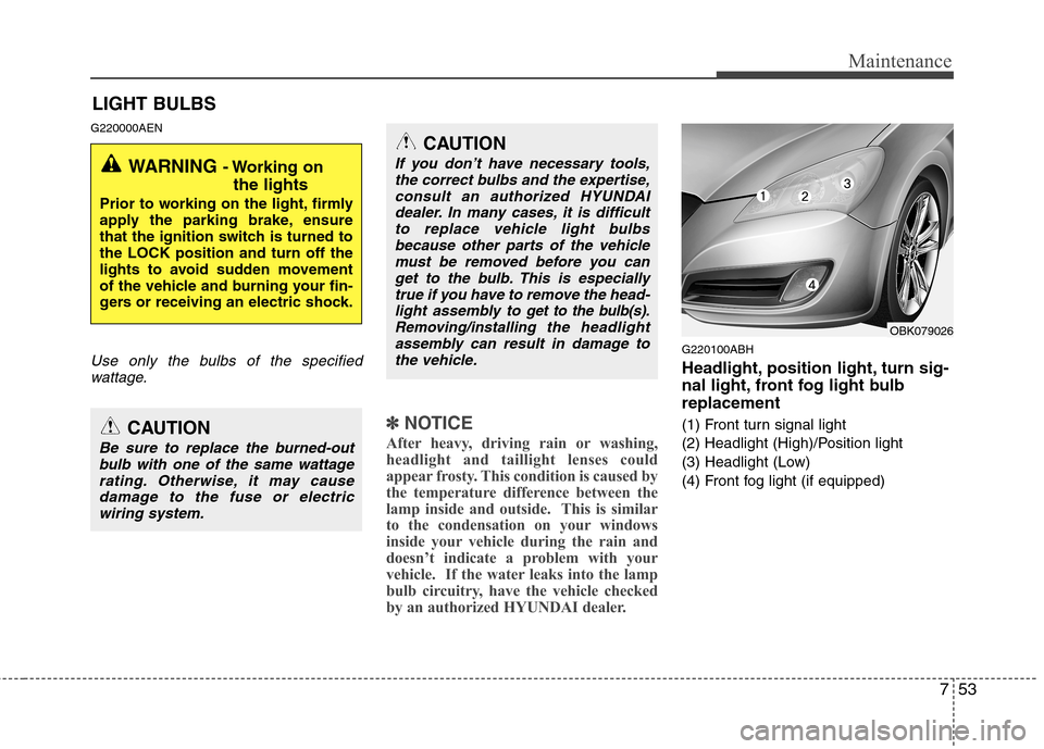
Headlight, position light, turn sig-
nal light, front fog light bulbreplacement
(1) Front turn signal light
(2) Headlight (High)/Position light
(3) Headlight (Low)
(4) Front fog light (if equipped)
WARNING - Working on
the lights
Prior to working on the light, firmly
apply the parking brake, ensure
that the ignition switch is turned tothe LOCK position and turn off the
lights to avoid sudden movement
of the vehicle and burning your fin-
gers or receiving an electric shock.
CAUTION
Be sure to replace the burned-out bulb with one of the same wattage
rating. Otherwise, it may cause damage to the fuse or electricwiring system.
CAUTION
If you don’t have necessary tools,the correct bulbs and the expertise,
consult an authorized HYUNDAIdealer. In many cases, it is difficultto replace vehicle light bulbs because other parts of the vehicle
must be removed before you canget to the bulb. This is especiallytrue if you have to remove the head-
light assembly to
get to the bulb(s).
Removing/installingthe headlight
assembly can result in damage to the vehicle.OBK079026
Page 299 of 322

Maintenance
56
7
Turn signal light bulb replacement
6. Remove the socket from the assembly
by turning the socket counter clock-
wise until the tabs on the socket align
with the slots on the assembly.
7. Remove the bulb from the socket by pressing it in and rotating it until the
tabs on the bulb align with the slots in
the socket. Pull the bulb out of the
socket.
8. Insert a new bulb by inserting it into the socket and rotating it until it locks
into place.
9. Install the socket into the assembly by aligning the tabs on the socket with the
slots in the assembly. Push the socket
into the assembly and turn the socket
clockwise. G220103AENFront fog light bulb replacement
1. Remove the front bumper under cover
and reach your hand into the back of
the front bumper.
2. Disconnect the power connector from the socket.
3. Remove the bulb-socket from the housing by turning the socket counter
clockwise until the tabs on the socketalign with the slots on the housing.
4. Install the new bulb-socket into the housing by aligning the tabs on the
socket with the slots in the housing.
Push the socket into the housing and
turn the socket clockwise.
5. Connect the power connector to the socket.
6. Reinstall the front bumper under cover. G220102BEN
Headlight (HID type) bulb replace-
ment
If the light bulb is not operating, have the
vehicle checked by an authorized
HYUNDAI dealer.
OBK079046OBK079052N
WARNING - HID Headlight
low beam (if equipped)
Do not attempt to replace or
inspect the low beam (XENON bulb)
due to electric shock danger. If the
low beam (XENON bulb) is not
working, have your vehicle checked
by an authorized HYUNDAI Dealer