2010 HUMMER H3 battery
[x] Cancel search: batteryPage 218 of 410

9-34 Driving and Operating
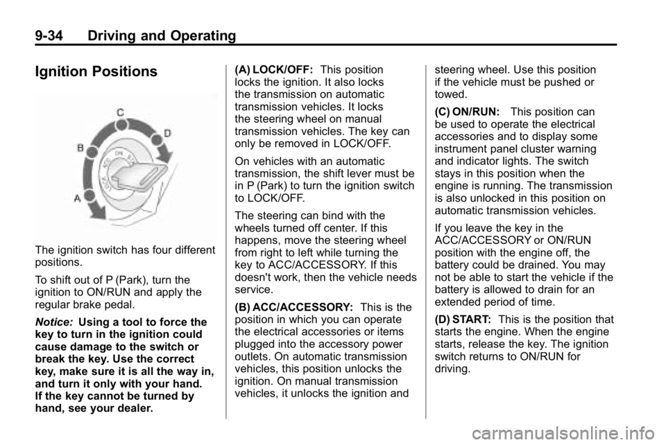
Ignition Positions
The ignition switch has four different
positions.
To shift out of P (Park), turn the
ignition to ON/RUN and apply the
regular brake pedal.
Notice:Using a tool to force the
key to turn in the ignition could
cause damage to the switch or
break the key. Use the correct
key, make sure it is all the way in,
and turn it only with your hand.
If the key cannot be turned by
hand, see your dealer. (A) LOCK/OFF:
This position
locks the ignition. It also locks
the transmission on automatic
transmission vehicles. It locks
the steering wheel on manual
transmission vehicles. The key can
only be removed in LOCK/OFF.
On vehicles with an automatic
transmission, the shift lever must be
in P (Park) to turn the ignition switch
to LOCK/OFF.
The steering can bind with the
wheels turned off center. If this
happens, move the steering wheel
from right to left while turning the
key to ACC/ACCESSORY. If this
doesn't work, then the vehicle needs
service.
(B) ACC/ACCESSORY: This is the
position in which you can operate
the electrical accessories or items
plugged into the accessory power
outlets. On automatic transmission
vehicles, this position unlocks the
ignition. On manual transmission
vehicles, it unlocks the ignition and steering wheel. Use this position
if the vehicle must be pushed or
towed.
(C) ON/RUN:
This position can
be used to operate the electrical
accessories and to display some
instrument panel cluster warning
and indicator lights. The switch
stays in this position when the
engine is running. The transmission
is also unlocked in this position on
automatic transmission vehicles.
If you leave the key in the
ACC/ACCESSORY or ON/RUN
position with the engine off, the
battery could be drained. You may
not be able to start the vehicle if the
battery is allowed to drain for an
extended period of time.
(D) START: This is the position that
starts the engine. When the engine
starts, release the key. The ignition
switch returns to ON/RUN for
driving.
Page 220 of 410

9-36 Driving and Operating
To prevent gear damage, this
system also prevents cranking if
the engine is already running.
Engine cranking can be stopped
by turning the ignition switch to
ACC/ACCESSORY or
LOCK/OFF.
Notice: Cranking the engine for
long periods of time, by returning
the key to the START position
immediately after cranking has
ended, can overheat and damage
the cranking motor, and drain the
battery. Wait at least 15 seconds
between each try, to let the
cranking motor cool down.
2. If the engine does not start
after 5‐10 seconds, especially
in very cold weather (below 0°F
or−18°C), it could be flooded
with too much gasoline. Push
the accelerator pedal all the way
to the floor and holding it there
as you hold the key in START
for a maximum of 15 seconds. Wait at least 15 seconds
between each try, to allow the
cranking motor to cool. When
the engine starts, let go of the
key and accelerator. If the
vehicle starts briefly but then
stops again, repeat the
procedure. This clears the extra
gasoline from the engine. Do not
race the engine immediately
after starting it. Operate the
engine and transmission gently
until the oil warms up and
lubricates all moving parts.
Notice: The engine is designed to
work with the electronics in the
vehicle. If you add electrical
parts or accessories, you could
change the way the engine
operates. Before adding electrical
equipment, check with your
dealer. If you do not, the engine
might not perform properly. Any
resulting damage would not be
covered by the vehicle warranty.Engine Coolant Heater
The engine coolant heater can
provide easier starting and better
fuel economy during engine
warm-up in cold weather conditions
at or below −18°C (0°F). Vehicles
with an engine coolant heater
should be plugged in at least
four hours before starting. An
internal thermostat in the plug-end
of the cord may exist which will
prevent engine coolant heater
operation at temperatures
above −18°C (0° F).
To Use the Engine Coolant
Heater
1. Turn off the engine.
2. Open the hood and unwrap
the electrical cord. The cord
is located in the engine
compartment behind the
underhood fuse block on the
driver side of the vehicle.
Page 223 of 410

Driving and Operating 9-39
The shift lock release is always
functional except in the case of a
an uncharged or low voltage (less
than 9 volt) battery.
If the vehicle has an uncharged
battery or a battery with low voltage,
try charging or jump starting the
battery. SeeJump Starting
on
page 10‑86for more information.
To shift out of P (Park):
1. Apply the brake pedal.
2. Then press the shift lever button.
3. Move the shift lever to the desired position. If you still are unable to shift out
of P (Park):
1. Fully release the shift lever
button.
2. While holding down the brake pedal, press the shift lever
button again.
3. Move the shift lever to the desired position.
If you still cannot move the shift
lever from P (Park), consult your
dealer or a professional towing
service.
Parking
If the vehicle has a manual
transmission, before you get out of
the vehicle, move the shift lever into
R (Reverse), and firmly apply the
parking brake. Once the shift lever
has been placed into R (Reverse)
with the clutch pedal pressed in,
turn the ignition key to LOCK/OFF,
remove the key and release the
clutch.
If you are parking on a hill, or if
the vehicle is pulling a trailer, see
Driving Characteristics and Towing
Tips on page 9‑70.
Page 239 of 410

Driving and Operating 9-55
To lock the rear axle, do the
following:
1. Place the transfer case in the4LO Lock mode. This is the
only mode which will allow
the rear axle to lock. See
Four-Wheel Drive
on page 9‑46for more information regarding
the transfer case and
4LO Lock mode.
2. Press the rear axle locking button with the vehicle moving
less than 26 km/h (16 mph).
The light in the button stops flashing
and remains illuminated when the
rear axle is locked.
Notice: If you try to lock the axle
while the vehicle is stuck and the
tires are spinning, the vehicle's
drivetrain could be damaged. The repairs would not be covered
by the vehicle warranty. Always
lock the axle before attempting
situations and/or navigating
terrain which could possibly
cause the vehicle to become
stuck.
The locking rear axle will be
disengaged when the wheel speed
is greater than 64 km/h (40 mph),
if the vehicle's battery is low and/or
the transfer case is shifted out of
4LO Lock mode.
Notice:
If the vehicle's axle
is locked while driving on
pavement, the drivetrain could be
damaged. Repairs would not be
covered by the vehicle warranty.
Do not use the locking axle on
pavement. If four-wheel drive is
needed when traveling on
pavement, use only 4HI.
Locking Front Axle
For vehicles with this feature, the
locking front axle, used with the
locking rear axle, can give the
vehicle additional traction when
traveling in off-road situations such
as mud, snow, sand, steep hills and
uneven terrain.
The button used to turn the locking
front axle on or off is located on the
instrument panel.
Before the front axle can be locked,
the rear axle must be locked.
Page 240 of 410

9-56 Driving and Operating
To lock the front and rear axles:
1. Place the transfer case in the4LO Lock mode. This is the
only mode which allows the
front and rear axles to lock.
See Four-Wheel Drive
on
page 9‑46for more information
regarding the transfer case and
4LO Lock mode.
2. Press the rear axle locking button with the vehicle moving
less than 16 mph (26 km/h).
3. Wait for the light in the button to stop flashing and remain
illuminated to show that the rear
axle is locked.
4. Press the front axle locking button with the vehicle stopped
or moving less than 26 km/h
(16 mph). 5. Wait for the light in the button
to stop flashing and remain
illuminated to show that the front
axle is locked.
Notice: If you try to lock the axle
while the vehicle is stuck and the
tires are spinning, the vehicle's
drivetrain could be damaged.
The repairs would not be covered
by the vehicle warranty. Always
lock the axle before attempting
situations and/or navigating
terrain which could possibly
cause the vehicle to become
stuck. Locking axles will be disengaged
when the wheel speed is greater
than 64 km/h (40 mph), if the
vehicle's battery is low and/or the
transfer case is shifted out of
4LO Lock mode.
Notice:
If the vehicle's axle
is locked while driving on
pavement, the drivetrain could be
damaged. Repairs would not be
covered by the vehicle warranty.
Do not use the locking axle on
pavement. If four-wheel drive is
needed when traveling on
pavement, use only 4HI.
Page 264 of 410

9-80 Driving and Operating
The trailer towing harness contains
the following seven trailer circuits:
.Yellow: Left Stop/Turn Signal
.Dark Green: Right Stop/Turn
Signal
.Brown: Taillamps
.White: Ground
.Light Green: Back-up Lamps
.Red: Battery Feed
.Dark Blue: Trailer Brake
If charging a remote (non‐vehicle)
battery, turn on the headlamps to
boost the vehicle system voltage to
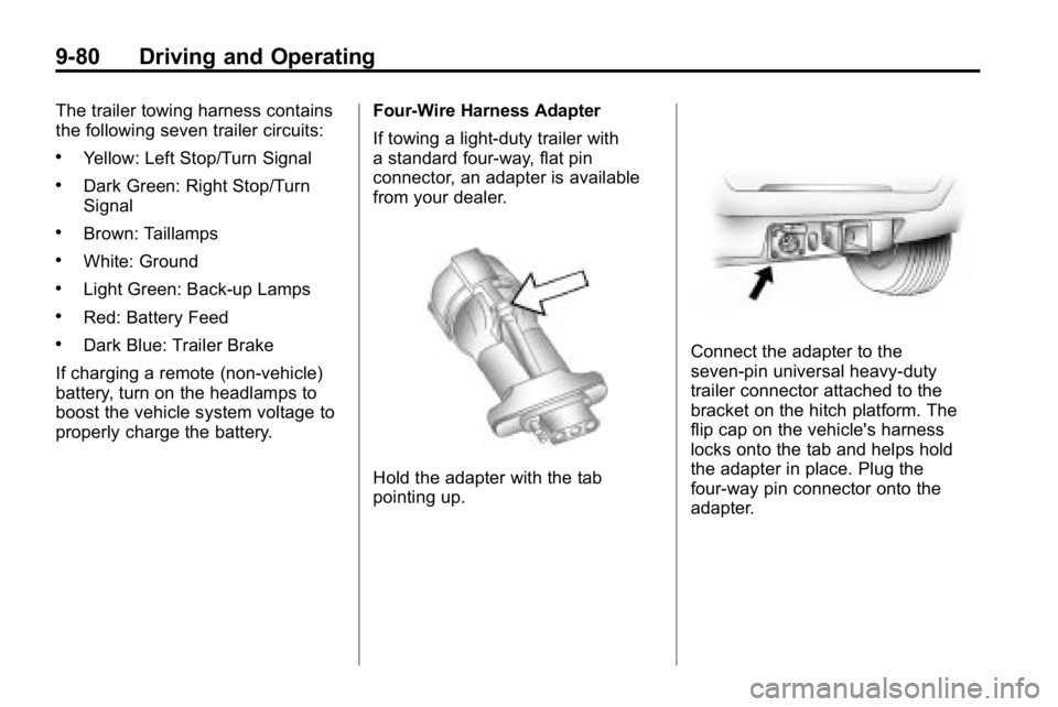
properly charge the battery. Four-Wire Harness Adapter
If towing a light-duty trailer with
a standard four-way, flat pin
connector, an adapter is available
from your dealer.
Hold the adapter with the tab
pointing up.
Connect the adapter to the
seven‐pin universal heavy‐duty
trailer connector attached to the
bracket on the hitch platform. The
flip cap on the vehicle's harness
locks onto the tab and helps hold
the adapter in place. Plug the
four-way pin connector onto the
adapter.
Page 265 of 410

Driving and Operating 9-81
Trailer Brake Control Wiring
Harness
The trailer brake control wiring
harness is located under the
instrument panel to the right of the
steering column. The wires are
taped to the harness that goes
to the courtesy light under the
instrument panel. The harness
has the following wires:
.Red Wire: AUX B+
.Black Wire: Ground
.Light Blue Wire: Brake Signal
.Dark Blue Wire: Trailer Brakes
Trailer Recommendations
Subtract the hitch loads from the
Cargo Weight Rating (CWR). CWR
is the maximum weight of the load
the vehicle can carry. It does not
include the weight of the people
inside, but you can figure about
68 kg (150 lbs) for each passenger.
The total cargo load must not be
more than the vehicles CWR.
Weigh the vehicle with the trailer
attached, so the GVWR or GAWR
are not exceeded. If using a
weight-distributing hitch, weigh the
vehicle without the spring bars in
place.
The best performance is obtained
by correctly spreading out the
weight of the load and choosing the
correct hitch and trailer brakes.
For more information seeTrailer
Towing on page 9‑74.
Conversions and
Add-Ons
Add-On Electrical
Equipment
Notice: Do not add anything
electrical to the vehicle unless
you check with your dealer first.
Some electrical equipment can
damage the vehicle and the
damage would not be covered
by the vehicle's warranty. Some
add-on electrical equipment can
keep other components from
working as they should.
Add-on equipment can drain the
vehicle battery, even if the vehicle is
not operating.
The vehicle has an airbag system.
Before attempting to add anything
electrical to the vehicle, see
Servicing the Airbag-Equipped
Vehicle
on page 3‑40and Adding
Equipment to the Airbag-Equipped
Vehicle on page 3‑40.
Page 267 of 410

Vehicle Care 10-1
Vehicle Care
General Information
General Information . . . . . . . . . . 10-2
California Proposition65 Warning . . . . . . . . . . . . . . . . . 10-2
California Perchlorate Materials Requirements . . . . 10-3
Accessories and Modifications . . . . . . . . . . . . . . . 10-3
Vehicle Checks
Doing Your OwnService Work . . . . . . . . . . . . . . . 10-4
Hood . . . . . . . . . . . . . . . . . . . . . . . . 10-5
Engine Compartment Overview . . . . . . . . . . . . . . . . . . . 10-6
Engine Oil . . . . . . . . . . . . . . . . . . . 10-9
Engine Oil Life System . . . . . 10-11
Automatic Transmission Fluid . . . . . . . . . . . . . . . . . . . . . . 10-12
Manual Transmission Fluid . . . . . . . . . . . . . . . . . . . . . . 10-15 Hydraulic Clutch . . . . . . . . . . . . 10-16
Engine Air Cleaner/Filter . . . . 10-17
Cooling System . . . . . . . . . . . . 10-18
Engine Coolant . . . . . . . . . . . . . 10-19
Engine Overheating . . . . . . . . 10-22
Engine Fan . . . . . . . . . . . . . . . . . 10-24
Power Steering Fluid . . . . . . . 10-24
Washer Fluid . . . . . . . . . . . . . . . 10-25
Brakes . . . . . . . . . . . . . . . . . . . . . 10-26
Brake Fluid . . . . . . . . . . . . . . . . . 10-27
Battery . . . . . . . . . . . . . . . . . . . . . 10-28
Four-Wheel Drive . . . . . . . . . . . 10-29
Front Axle . . . . . . . . . . . . . . . . . . 10-29
Rear Axle . . . . . . . . . . . . . . . . . . 10-29
Starter Switch Check . . . . . . . 10-30
Automatic Transmission Shift
Lock Control System
Check . . . . . . . . . . . . . . . . . . . . . 10-30
Ignition Transmission Lock Check . . . . . . . . . . . . . . . . . . . . . 10-31
Park Brake and P (Park) Mechanism Check . . . . . . . . 10-31
Wiper Blade Replacement . . . . . . . . . . . . . . 10-32
Headlamp Aiming
Headlamp Aiming . . . . . . . . . . 10-33
Bulb Replacement
Bulb Replacement . . . . . . . . . . 10-35
Halogen Bulbs . . . . . . . . . . . . . . 10-35
Headlamps . . . . . . . . . . . . . . . . . 10-35
Taillamps, Turn Signal,Stoplamps, and Back-Up
Lamps (H3) . . . . . . . . . . . . . . . 10-35
Taillamps, Turn Signal, Stoplamps, and Back-Up
Lamps (H3T) . . . . . . . . . . . . . . 10-36
License Plate Lamp . . . . . . . . 10-37
Replacement Bulbs . . . . . . . . . 10-37
Electrical System
Electrical System Overload . . . . . . . . . . . . . . . . . . 10-38
Fuses and Circuit Breakers . . . . . . . . . . . . . . . . . . 10-39
Engine Compartment Fuse Block . . . . . . . . . . . . . . . . . . . . . 10-39