2010 GMC SIERRA seats
[x] Cancel search: seatsPage 247 of 630

Outlet Adjustment
Use the air outlets located in the center and on the side
of the instrument panel to direct the airflow. Use the
thumbwheels near the air outlets to open or close off
the airflow.
Operation Tips
.Clear away any ice, snow, or leaves from air inlets
at the base of the windshield that could block the
flow of air into the vehicle.
.Keep the path under the front seats clear of
objects to help circulate the air inside of the vehicle
more effectively.
.Use of non‐GM approved hood deflectors can
adversely affect the performance of the system.
Check with your dealer/retailer before adding
equipment to the outside of the vehicle.
Warning Lights, Gages, and
Indicators
Warning lights and gages can signal that something is
wrong before it becomes serious enough to cause an
expensive repair or replacement. Paying attention to the
warning lights and gages could prevent injury.
Warning lights come on when there might be or there is
a problem with one of the vehicle's functions. Some
warning lights come on briefly when the engine is
started to indicate they are working.
Gages can indicate when there might be or there is a
problem with one of the vehicle's functions. Often gages
and warning lights work together to indicate a problem
with the vehicle.
When one of the warning lights comes on and stays on
while driving, or when one of the gages shows there
could be a problem, check the section that explains
what to do. Follow this manual's advice. Waiting to do
repairs can be costly and even dangerous.
4-29
Page 274 of 630

If the tire pressure display shows dashes instead of a
value, there may be a problem with your vehicle. If this
consistently occurs, see your dealer/retailer for service.
Trailer Gain and Output
On vehicles with the Integrated Trailer Brake Control
(ITBC) system, the trailer brake display appears in
the DIC. Press the vehicle information button until
TRAILER GAIN and OUTPUT display.
TRAILER GAIN shows the trailer gain setting. This
setting can be adjusted from 0.0 to 10.0 with either a
trailer connected or disconnected. To adjust this setting,
see“Integrated Trailer Brake Control System” under
Towing a Trailer
on page 5‑50for more information.
OUTPUT shows the power output to the trailer anytime
a trailer with electric brakes is connected. Output is
displayed in 0 to 10 bars. Dashes may appear in the
OUTPUT display. See “Integrated Trailer Brake Control
System” underTowing a Trailer
on page 5‑50for more
information.
Engine Hours
Press the vehicle information button until ENGINE
HOURS displays. This display shows the total number
of hours the engine has run.
Relearn Remote Key
This display allows you to match Remote Keyless Entry
(RKE) transmitters to your vehicle. This procedure will
erase all previously learned transmitters. Therefore,
they must be relearned as additional transmitters.
To match an RKE transmitter to your vehicle:
1. Press the vehicle information button until PRESS
VTO RELEARN REMOTE KEY displays.
2. Press the set/reset button until REMOTE KEY LEARNING ACTIVE is displayed.
3. Press and hold the lock and unlock buttons on the first transmitter at the same time for about
15 seconds.
On vehicles with memory recall seats, the first
transmitter learned will match driver 1 and the
second will match driver 2.
A chime will sound indicating that the transmitter
is matched.
4. To match additional transmitters at this time, repeat Step 3.
Each vehicle can have a maximum of eight
transmitters matched to it.
5. To exit the programming mode, you must cycle the key to LOCK/OFF.
4-56
Page 279 of 630

Remember, you must reset the OIL LIFE display
yourself after each oil change. It will not reset itself.
Also, be careful not to reset the OIL LIFE display
accidentally at any time other than when the oil has just
been changed. It cannot be reset accurately until the
next oil change. To reset the engine oil life system,
seeEngine Oil Life System on page 6‑20.
Relearn Tire Positions
Your vehicle may have this display. To access this
display, the vehicle must be in P (Park). If your vehicle
has the Tire Pressure Monitor System (TPMS), after
rotating the tires or after replacing a tire or sensor, the
system must re-learn the tire positions. To re-learn the
tire positions, see Tire Pressure Monitor System
on
page 6‑75. See Tire Inspection and Rotationon
page 6‑80and DIC Warnings and Messageson
page 4‑65for more information.
Relearn Remote Key
To access this display, the vehicle must be in P (Park).
This display allows you to match Remote Keyless Entry
(RKE) transmitters to your vehicle. This procedure will
erase all previously learned transmitters. Therefore,
they must be relearned as additional transmitters. To match an RKE transmitter to your vehicle:
1. Press the trip odometer reset stem until RELEARN REMOTE KEY displays.
2. Press and hold the trip odometer reset stem for three seconds.
The message REMOTE KEY LEARNING ACTIVE
will display.
3. Press and hold the lock and unlock buttons on the first transmitter at the same time for about
15 seconds.
On vehicles with memory recall seats, the first
transmitter learned will match driver 1 and the
second will match driver 2.
A chime will sound indicating that the transmitter
is matched.
4. To match additional transmitters at this time, repeat Step 3.
Each vehicle can have a maximum of eight
transmitters matched to it.
5. To exit the programming mode, you must cycle the key to LOCK/OFF.
4-61
Page 282 of 630

Compass Calibration
The compass can be manually calibrated. Only calibrate
the compass in a magnetically clean and safe location,
such as an open parking lot, where driving the vehicle
in circles is not a danger. It is suggested to calibrate
away from tall buildings, utility wires, manhole covers,
or other industrial structures, if possible.
If CAL should ever appear in the DIC display,
the compass should be calibrated.
If the DIC display does not show a heading, for
example, N for North, or the heading does not change
after making turns, there may be a strong magnetic field
interfering with the compass. Such interference may be
caused by a magnetic CB or cell phone antenna mount,
a magnetic emergency light, magnetic note pad holder,
or any other magnetic item. Turn off the vehicle, move
the magnetic item, then turn on the vehicle and calibrate
the compass.To calibrate the compass, use the following procedure:Compass Calibration Procedure
1. Before calibrating the compass, make sure the
compass zone is set to the variance zone in which
the vehicle is located. See “Compass Variance
(Zone) Procedure” earlier in this section.
Do not operate any switches such as window,
sunroof, climate controls, seats, etc. during the
calibration procedure.
2. Press the vehicle information button until PRESS
VTO CALIBRATE COMPASS displays. Or, if the
vehicle does not have DIC buttons, press the trip
odometer reset stem until CALIBRATE COMPASS
displays.
3. Press the set/reset button to start the compass calibration. Or, if the vehicle does not have DIC
buttons, press and hold the trip odometer reset
stem for two seconds to start the compass
calibration.
4. The DIC will display CALIBRATING: DRIVE IN CIRCLES. Drive the vehicle in tight circles at less
than 5 mph (8 km/h) to complete the calibration.
The DIC will display CALIBRATION COMPLETE
for a few seconds when the calibration is complete.
The DIC display will then return to the
previous menu.
4-64
Page 283 of 630

DIC Warnings and Messages
Messages are displayed on the DIC to notify the
driver that the status of the vehicle has changed and
that some action may be needed by the driver to
correct the condition. Multiple messages may appear
one after another.
Some messages may not require immediate action, but
you can press any of the DIC buttons on the instrument
panel or the trip odometer reset stem on the instrument
panel cluster to acknowledge that you received the
messages and to clear them from the display.
Some messages cannot be cleared from the DIC
display because they are more urgent. These
messages require action before they can be cleared.
You should take any messages that appear on the
display seriously and remember that clearing the
messages will only make the messages disappear,
not correct the problem.
The following are the possible messages that can be
displayed and some information about them.
If your vehicle has the DURAMAX
®Diesel engine, see
the DURAMAX Diesel manual for more information.
BATTERY LOW START VEHICLE
When the vehicle’ s battery is severely discharged,
this message will display and four chimes may sound.
Start the vehicle immediately. If the vehicle is not
started and the battery continues to discharge, the
climate controls, heated seats, and audio systems will
shut off and the vehicle may require a jump start.
These systems will function again after the vehicle
is started.
CHANGE ENGINE OIL SOON
This message displays when the engine oil needs to be
changed. When you change the engine oil, be sure to
reset the CHANGE ENGINE OIL SOON message.
See Engine Oil Life System
on page 6‑20for
information on how to reset the message. See Engine
Oil
on page 6‑18and Scheduled Maintenanceon
page 7‑3for more information.
4-65
Page 403 of 630

{WARNING:
Things you put inside your vehicle can strike
and injure people in a sudden stop or turn,
or in a crash.
.Put things in the cargo area of your
vehicle. Try to spread the weight evenly.
.Never stack heavier things, like
suitcases, inside the vehicle so that some
of them are above the tops of the seats.
.Do not leave an unsecured child restraint
in your vehicle.
.When you carry something inside the
vehicle, secure it whenever you can.
.Do not leave a seat folded down unless
you need to.
There is also important loading information for
off-road driving in this manual. See “Loading Your
Vehicle for Off-Road Driving“ underOff-Road
Driving
on page 5‑11.
Two-Tiered Loading
Depending on the model of your pick‐up, you
can create an upper load platform by positioning
two or four 2 inches (5 cm) by 6 inches (15 cm)
wooden planks across the width of the pickup box.
The planks must be inserted in the pickup box
depressions. The length of the planks must allow
for at least a 3/4 inch (2 cm) bearing surface on
each end of the plank.
When using this upper load platform, be sure
the load is securely tied down to prevent it from
shifting. The load's center of gravity should be
positioned in a zone over the rear axle. The zone
is located in the area between the front of each
wheel well and the rear of each wheel well. The
center of gravity height must not extend above the
top of the pickup box flareboard.
Any load that extends beyond the vehicle's
taillamp area must be properly marked according
to local laws and regulations.
Remember not to exceed the Gross Axle Weight
Rating (GAWR) of the front or rear axle.
5-35
Page 516 of 630

Tire Terminology and Definitions
Air Pressure:The amount of air inside the tire
pressing outward on each square inch of the tire.
Air pressure is expressed in pounds per square
inch (psi) or kilopascal (kPa).
Accessory Weight
:This means the combined
weight of optional accessories. Some examples of
optional accessories are, automatic transmission,
power steering, power brakes, power windows,
power seats, and air conditioning.
Aspect Ratio
:The relationship of a tire's height
to its width.
Belt
:A rubber coated layer of cords that is
located between the plies and the tread. Cords
may be made from steel or other reinforcing
materials.
Bead
:The tire bead contains steel wires wrapped
by steel cords that hold the tire onto the rim.
Bias Ply Tire
:A pneumatic tire in which the plies
are laid at alternate angles less than 90 degrees
to the centerline of the tread. Cold Tire Pressure
:The amount of air pressure
in a tire, measured in pounds per square inch (psi)
or kilopascals (kPa) before a tire has built up heat
from driving. See Inflation - Tire Pressure
on
page 6‑72
.
Curb Weight
:The weight of a motor vehicle with
standard and optional equipment including the
maximum capacity of fuel, oil, and coolant, but
without passengers and cargo.
DOT Markings
:A code molded into the sidewall
of a tire signifying that the tire is in compliance
with the U.S. Department of Transportation (DOT)
motor vehicle safety standards. The DOT code
includes the Tire Identification Number (TIN), an
alphanumeric designator which can also identify
the tire manufacturer, production plant, brand, and
date of production.
GVWR
:Gross Vehicle Weight Rating. See
Loading the Vehicle
on page 5‑30.
GAWR FRT
:Gross Axle Weight Rating for the
front axle. See Loading the Vehicle
on page 5‑30.
GAWR RR
:Gross Axle Weight Rating for the rear
axle. See Loading the Vehicle
on page 5‑30.
6-70
Page 549 of 630

For center caps, place the cap on the wheel and tap it
into place until it seats flush with the wheel. The cap
only goes on one way. Be sure to line up the tab on
the center cap with the indentation on the wheel.
For bolt-on hub caps, align the plastic nut caps with the
wheel nuts and then tighten by hand. Then use the
wheel wrench to tighten.
Secondary Latch System
This vehicle may have an underbody-mounted tire hoist
assembly equipped with a secondary latch system. It is
designed to stop the spare tire from suddenly falling off
your vehicle. For the secondary latch to work, the spare
must be installed with the valve stem pointing down.
SeeStoring a Flat or Spare Tire and Tools
on
page 6‑106.
{WARNING:
Before beginning this procedure read all the
instructions. Failure to read and follow the
instructions could damage the hoist assembly and
you and others could get hurt. Read and follow
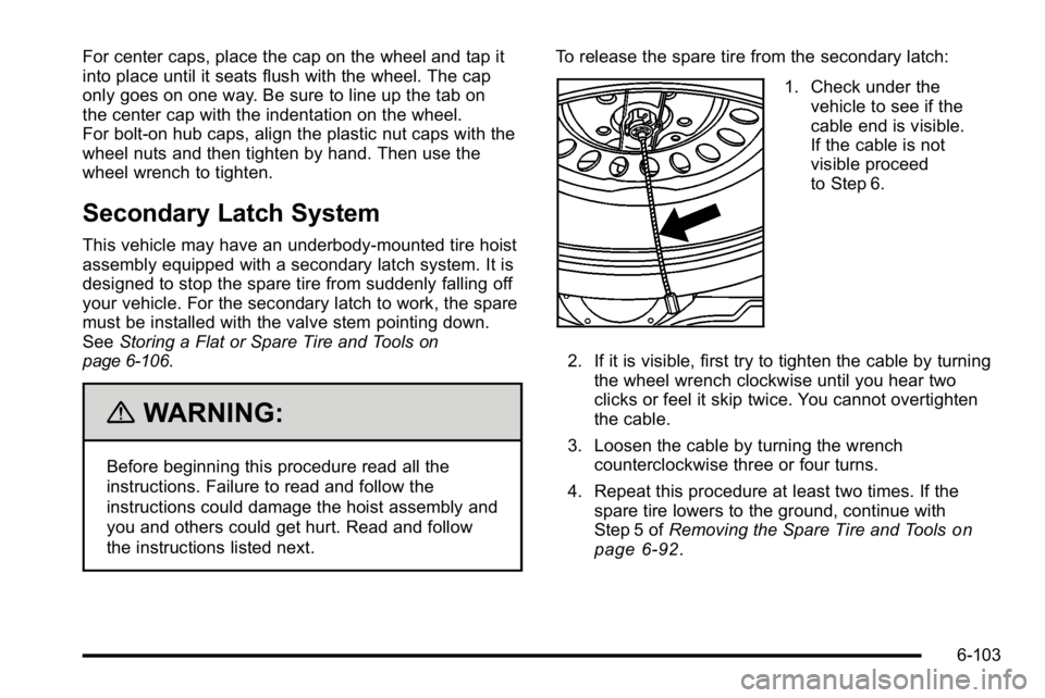
the instructions listed next. To release the spare tire from the secondary latch:
1. Check under the
vehicle to see if the
cable end is visible.
If the cable is not
visible proceed
to Step 6.
2. If it is visible, first try to tighten the cable by turning the wheel wrench clockwise until you hear two
clicks or feel it skip twice. You cannot overtighten
the cable.
3. Loosen the cable by turning the wrench counterclockwise three or four turns.
4. Repeat this procedure at least two times. If the spare tire lowers to the ground, continue with
Step 5 of Removing the Spare Tire and Tools
on
page 6‑92.
6-103