Page 551 of 630

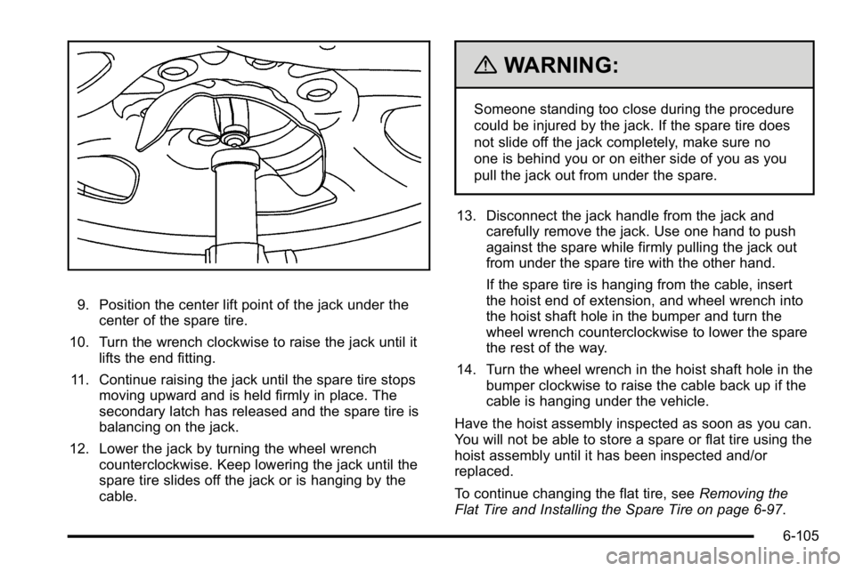
9. Position the center lift point of the jack under thecenter of the spare tire.
10. Turn the wrench clockwise to raise the jack until it lifts the end fitting.
11. Continue raising the jack until the spare tire stops moving upward and is held firmly in place. The
secondary latch has released and the spare tire is
balancing on the jack.
12. Lower the jack by turning the wheel wrench counterclockwise. Keep lowering the jack until the
spare tire slides off the jack or is hanging by the
cable.
{WARNING:
Someone standing too close during the procedure
could be injured by the jack. If the spare tire does
not slide off the jack completely, make sure no
one is behind you or on either side of you as you
pull the jack out from under the spare.
13. Disconnect the jack handle from the jack and carefully remove the jack. Use one hand to push
against the spare while firmly pulling the jack out
from under the spare tire with the other hand.
If the spare tire is hanging from the cable, insert
the hoist end of extension, and wheel wrench into
the hoist shaft hole in the bumper and turn the
wheel wrench counterclockwise to lower the spare
the rest of the way.
14. Turn the wheel wrench in the hoist shaft hole in the bumper clockwise to raise the cable back up if the
cable is hanging under the vehicle.
Have the hoist assembly inspected as soon as you can.
You will not be able to store a spare or flat tire using the
hoist assembly until it has been inspected and/or
replaced.
To continue changing the flat tire, see Removing the
Flat Tire and Installing the Spare Tire on page 6‑97.
6-105
Page 552 of 630
Storing a Flat or Spare Tire and
Tools
{WARNING:
Storing a jack, a tire, or other equipment in the
passenger compartment of the vehicle could
cause injury. In a sudden stop or collision, loose
equipment could strike someone. Store all these
in the proper place.
Notice: Storing an aluminum wheel with a flat tire
under your vehicle for an extended period of time or
with the valve stem pointing up can damage the
wheel. Always stow the wheel with the valve stem
pointing down and have the wheel/tire repaired as
soon as possible.
Store the tire under the rear of the vehicle in the spare
tire carrier.
A. Flat or Spare Tire (Valve Stem
Pointed Down)
B. Hoist Assembly
C. Hoist Cable
D. Tire/Wheel Retainer
E. Hoist Shaft F. Hoist End of
Extension Tool
G. Hoist Shaft Access Hole H. Wheel Wrench I. Jack Handle Extensions
J. Spare Tire Lock (If Equipped)
1. Put the tire on the ground at the rear of the vehicle with the valve stem pointed down, and to the rear.
6-106
Page 553 of 630
2. Separate the tire/wheel retainer (D) from the guidepin. Pull the pin through the center of the wheel.
Tilt the retainer down and through the center wheel
opening.
Make sure the retainer is fully seated across the
underside of the wheel.3. Attach the wheel wrench (H) and extensions (I)together, as shown.
4. Insert the hoist end (F)through the hole (G) in
the rear bumper and
onto the hoist shaft.
Do not use the
chiseled end of the
wheel wrench.
6-107
Page 554 of 630
5. Raise the tire part way upward. Make sure theretainer is seated in the wheel opening.
6. Raise the tire fully against the underside of the vehicle by turning the wheel wrench clockwise until
you hear two clicks or feel it skip twice. You cannot
overtighten the cable.
7. Make sure the tire is stored securely. Push,pull (A), and then try to turn (B) the tire. If the tire
moves, use the wheel wrench to tighten the cable.
8. Reinstall the spare tire lock, if the vehicle has one. To store the jack and jack tools:
A. Wing Nut Retaining
Wheel Blocks
B. Wheel Blocks
C. Wing Nut Retaining Tool Kit
D. Wheel Wrench and Extensions E. Tool Bag
F. Jack Mounting Bracket
G. Jack H. Bolt Retaining Wheel Blocks
1. Put the tools (D) in the tool bag (E) and place them in the retaining bracket (C).
2. Tighten down the wing nut (C).
6-108
Page 555 of 630

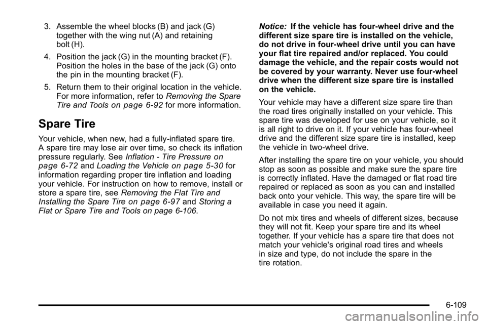
3. Assemble the wheel blocks (B) and jack (G)together with the wing nut (A) and retaining
bolt (H).
4. Position the jack (G) in the mounting bracket (F). Position the holes in the base of the jack (G) onto
the pin in the mounting bracket (F).
5. Return them to their original location in the vehicle. For more information, refer to Removing the Spare
Tire and Tools
on page 6‑92for more information.
Spare Tire
Your vehicle, when new, had a fully-inflated spare tire.
A spare tire may lose air over time, so check its inflation
pressure regularly. See Inflation - Tire Pressure
on
page 6‑72and Loading the Vehicleon page 5‑30for
information regarding proper tire inflation and loading
your vehicle. For instruction on how to remove, install or
store a spare tire, see Removing the Flat Tire and
Installing the Spare Tire
on page 6‑97and Storing a
Flat or Spare Tire and Tools on page 6‑106. Notice:
If the vehicle has four-wheel drive and the
different size spare tire is installed on the vehicle,
do not drive in four-wheel drive until you can have
your flat tire repaired and/or replaced. You could
damage the vehicle, and the repair costs would not
be covered by your warranty. Never use four-wheel
drive when the different size spare tire is installed
on the vehicle.
Your vehicle may have a different size spare tire than
the road tires originally installed on your vehicle. This
spare tire was developed for use on your vehicle, so it
is all right to drive on it. If your vehicle has four-wheel
drive and the different size spare tire is installed, keep
the vehicle in two-wheel drive.
After installing the spare tire on your vehicle, you should
stop as soon as possible and make sure the spare tire
is correctly inflated. Have the damaged or flat road tire
repaired or replaced as soon as you can and installed
back onto your vehicle. This way, the spare tire will be
available in case you need it again.
Do not mix tires and wheels of different sizes, because
they will not fit. Keep your spare tire and its wheel
together. If your vehicle has a spare tire that does not
match your vehicle's original road tires and wheels
in size and type, do not include the spare in the
tire rotation.
6-109
Page 561 of 630

Aluminum or Chrome-Plated Wheels
and Trim
The vehicle may have either aluminum or
chrome-plated wheels.
Keep the wheels clean using a soft clean cloth with mild
soap and water. Rinse with clean water. After rinsing
thoroughly, dry with a soft clean towel. A wax may then
be applied.
Notice:Chrome wheels and other chrome trim may
be damaged if the vehicle is not washed after
driving on roads that have been sprayed with
magnesium, calcium or sodium chloride. These
chlorides are used on roads for conditions such as
ice and dust. Always wash the vehicle's chrome
with soap and water after exposure.
Notice: Using strong soaps, chemicals, abrasive
polishes, cleaners, brushes, or cleaners that contain
acid on aluminum or chrome-plated wheels, could
damage the surface of the wheel(s). The repairs
would not be covered by the vehicle warranty.
Use only approved cleaners on aluminum or
chrome-plated wheels. The surface of these wheels is similar to the painted
surface of the vehicle. Do not use strong soaps,
chemicals, abrasive polishes, abrasive cleaners,
cleaners with acid, or abrasive cleaning brushes on
them because they could damage the surface.
Do not use chrome polish on aluminum wheels.
Notice:
Using chrome polish on aluminum wheels
could damage the wheels. The repairs would not be
covered by the vehicle warranty. Use chrome polish
on chrome wheels only.
Use chrome polish only on chrome-plated wheels, but
avoid any painted surface of the wheel, and buff off
immediately after application.
Notice: Driving the vehicle through an automatic
car wash that has silicone carbide tire cleaning
brushes, could damage the aluminum or
chrome-plated wheels. The repairs would not be
covered by the vehicle warranty. Never drive a
vehicle that has aluminum or chrome-plated wheels
through an automatic car wash that uses silicone
carbide tire cleaning brushes.
6-115
Page 565 of 630
Instrument Panel Fuse Block
The instrument panel fuse
block access door is
located on the driver side
edge of the instrument
panel.
Pull off the cover to access the fuse block.
The vehicle may not use all of the fuses shown. Fuses Usage
1 Rear Seats
2 Rear Accessory Power Outlet
3 Steering Wheel Controls Backlight
4 Driver Door Module
5 Dome Lamps, Driver Side Turn Signal
6 Driver Side Turn Signal, Stoplamp
7 Instrument Panel Back Lighting
8 Passenger Side Turn Signal,
Stoplamp
6-119
Page 573 of 630
ApplicationCapacities
English Metric
Fuel Tank
1500 Series Standard and Short Box 26.0 gal 98.0 L
1500 Series Long Box 34.0 gal 128.7 L
2500 Series Standard Box 26.0 gal 98.0 L
2500 Series and 3500 Series Long Box 34.0 gal 128.7 L
3500 Series Chassis Cab 50.0 gal 189.0 L
3500 Chassis Cab –Front Tank 27.0 gal 102.0 L
3500 Chassis Cab –Rear Tank (if equipped) 23.0 gal 87.0 L
Transmission Fluid (Pan Removal and Filter Replacement) Auto 4-Speed Transmission 4L60-E Electronic Transmission 5.0 qt4.7 L
Auto 6-Speed Transmission 6L80-E 6.0 qt5.7 L
Auto 6-Speed Transmission 6L90-E 6.3 qt6.0 L
Auto 6-Speed Transmission Allison 7.4 qt7.0 L
Transfer Case Fluid 1.6 qt1.5 L
Wheel Nut Torque 140 ft lb190Y
All capacities are approximate. When adding, be sure to fill to the approximate level, as recommended in this manual.
Recheck fluid level after filling.
6-127