2010 GMC SIERRA DENALI ECO mode
[x] Cancel search: ECO modePage 311 of 550
¨(Seek):Press to go to the next radio station while in
AM, FM, or XM™.
For vehicles with or without a navigation system:
Press
¨to go to the next track or chapter while
sourced to the CD or DVD slot.
Press
¨to select a track or a folder when navigating
folders on an iPod or USB device.
For vehicles with a navigation system:
1. Press and hold
¨until a beep is heard, to place
the radio into SCAN mode, a station will play for
five seconds before moving to the next station.
2. To stop the SCAN function, press
¨again.
While listening to a CD/DVD, press and hold
¨to
quickly move forward through the tracks. Release to
stop on the desired track.
+
e−e(Volume): Press to increase or to decrease
the volume.
Radio Reception
Frequency interference and static can occur during
normal radio reception if items such as cell phone
chargers, vehicle convenience accessories, and
external electronic devices are plugged into the
accessory power outlet. If there is interference or static,
unplug the item from the accessory power outlet.
AM
The range for most AM stations is greater than for FM,
especially at night. The longer range can cause station
frequencies to interfere with each other. For better radio
reception, most AM radio stations boost the power
levels during the day, and then reduce these levels
during the night. Static can also occur when things like
storms and power lines interfere with radio reception.
When this happens, try reducing the treble on the radio.
FM Stereo
FM signals only reach about 10 to 40 miles (16 to 65 km).
Although the radio has a built-in electronic circuit that
automatically works to reduce interference, some static
can occur, especially around tall buildings or hills,
causing the sound to fade in and out.
4-139
Page 360 of 550
Tow/Haul Mode
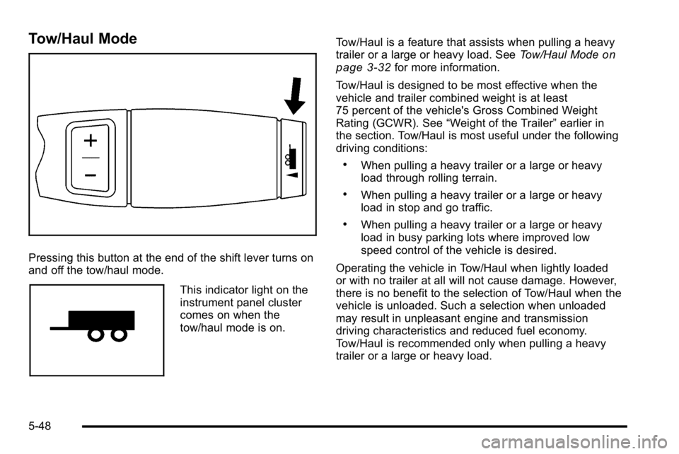
Pressing this button at the end of the shift lever turns on
and off the tow/haul mode.
This indicator light on the
instrument panel cluster
comes on when the
tow/haul mode is on.Tow/Haul is a feature that assists when pulling a heavy
trailer or a large or heavy load. See
Tow/Haul Mode
on
page 3‑32for more information.
Tow/Haul is designed to be most effective when the
vehicle and trailer combined weight is at least
75 percent of the vehicle's Gross Combined Weight
Rating (GCWR). See “Weight of the Trailer” earlier in
the section. Tow/Haul is most useful under the following
driving conditions:
.When pulling a heavy trailer or a large or heavy
load through rolling terrain.
.When pulling a heavy trailer or a large or heavy
load in stop and go traffic.
.When pulling a heavy trailer or a large or heavy
load in busy parking lots where improved low
speed control of the vehicle is desired.
Operating the vehicle in Tow/Haul when lightly loaded
or with no trailer at all will not cause damage. However,
there is no benefit to the selection of Tow/Haul when the
vehicle is unloaded. Such a selection when unloaded
may result in unpleasant engine and transmission
driving characteristics and reduced fuel economy.
Tow/Haul is recommended only when pulling a heavy
trailer or a large or heavy load.
5-48
Page 372 of 550
Trailer Wiring Harness
Heavy-Duty Trailer Wiring Harness Package
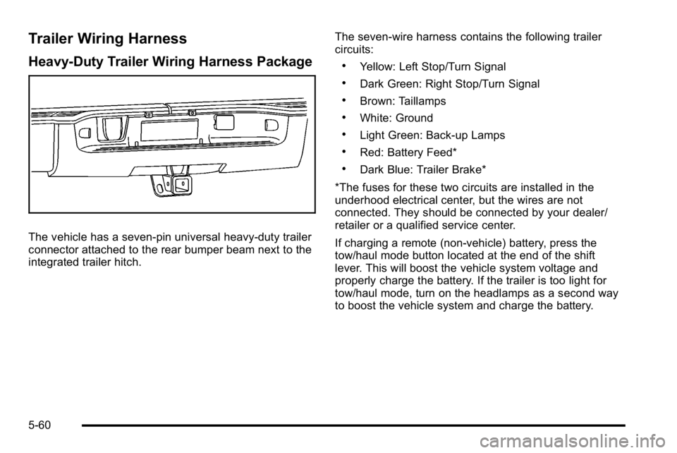
The vehicle has a seven-pin universal heavy-duty trailer
connector attached to the rear bumper beam next to the
integrated trailer hitch.The seven-wire harness contains the following trailer
circuits:
.Yellow: Left Stop/Turn Signal
.Dark Green: Right Stop/Turn Signal
.Brown: Taillamps
.White: Ground
.Light Green: Back-up Lamps
.Red: Battery Feed*
.Dark Blue: Trailer Brake*
*The fuses for these two circuits are installed in the
underhood electrical center, but the wires are not
connected. They should be connected by your dealer/
retailer or a qualified service center.
If charging a remote (non-vehicle) battery, press the
tow/haul mode button located at the end of the shift
lever. This will boost the vehicle system voltage and
properly charge the battery. If the trailer is too light for
tow/haul mode, turn on the headlamps as a second way
to boost the vehicle system and charge the battery.
5-60
Page 385 of 550
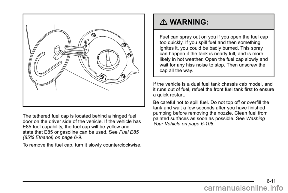
The tethered fuel cap is located behind a hinged fuel
door on the driver side of the vehicle. If the vehicle has
E85 fuel capability, the fuel cap will be yellow and
state that E85 or gasoline can be used. SeeFuel E85
(85% Ethanol) on page 6‑9.
To remove the fuel cap, turn it slowly counterclockwise.
{WARNING:
Fuel can spray out on you if you open the fuel cap
too quickly. If you spill fuel and then something
ignites it, you could be badly burned. This spray
can happen if the tank is nearly full, and is more
likely in hot weather. Open the fuel cap slowly and
wait for any hiss noise to stop. Then unscrew the
cap all the way.
If the vehicle is a dual fuel tank chassis cab model, and
it runs out of fuel, refuel the front fuel tank first to ensure
a quick restart.
Be careful not to spill fuel. Do not top off or overfill the
tank and wait a few seconds after you have finished
pumping before removing the nozzle. Clean fuel from
painted surfaces as soon as possible. See Washing
Your Vehicle on page 6‑108.
6-11
Page 443 of 550

Intended Outboard Sidewall:The side of an
asymmetrical tire, that must always face outward
when mounted on a vehicle.
Kilopascal (kPa)
:The metric unit for air
pressure.
Light Truck (LT‐Metric) Tire
:A tire used on light
duty trucks and some multipurpose passenger
vehicles.
Load Index
:An assigned number ranging from
1 to 279 that corresponds to the load carrying
capacity of a tire.
Maximum Inflation Pressure
:The maximum air
pressure to which a cold tire can be inflated. The
maximum air pressure is molded onto the
sidewall.
Maximum Load Rating
:The load rating for a tire
at the maximum permissible inflation pressure for
that tire.
Maximum Loaded Vehicle Weight
:The sum of
curb weight, accessory weight, vehicle capacity
weight, and production options weight. Normal Occupant Weight
:The number of
occupants a vehicle is designed to seat multiplied
by 150 lbs (68 kg). See Loading the Vehicle
on
page 5‑31
.
Occupant Distribution
:Designated seating
positions.
Outward Facing Sidewall
:The side of an
asymmetrical tire that has a particular side that
faces outward when mounted on a vehicle. The
side of the tire that contains a whitewall, bears
white lettering, or bears manufacturer, brand, and/
or model name molding that is higher or deeper
than the same moldings on the other sidewall of
the tire.
Passenger (P-Metric) Tire
:A tire used on
passenger cars and some light duty trucks and
multipurpose vehicles.
Recommended Inflation Pressure
:Vehicle
manufacturer's recommended tire inflation
pressure as shown on the tire placard. See
Inflation - Tire Pressure
on page 6‑71and Loading
the Vehicle
on page 5‑31.
6-69
Page 451 of 550

TPMS Sensor Matching Process
Each TPMS sensor has a unique identification code.
Any time you rotate your vehicle's tires or replace one
or more of the TPMS sensors, the identification codes
will need to be matched to the new tire/wheel position.
The sensors are matched to the tire/wheel positions in
the following order: driver side front tire, passenger side
front tire, passenger side rear tire, and driver side
rear tire using a TPMS diagnostic tool. See your
dealer/retailer for service.
The TPMS sensors can also be matched to each
tire/wheel position by increasing or decreasing the tire's
air pressure. If increasing the tire's air pressure, do not
exceed the maximum inflation pressure indicated on the
tire's sidewall.
To decrease air-pressure out of a tire you can use the
pointed end of the valve cap, a pencil-style air pressure
gage, or a key.
You have two minutes to match the first tire/wheel
position, and five minutes overall to match all four tire/
wheel positions. If it takes longer than two minutes, to
match the first tire and wheel, or more than five minutes
to match all four tire and wheel positions the matching
process stops and you need to start over.The TPMS sensor matching process is outlined below:
1. Set the parking brake.
2. Turn the ignition switch to ON/RUN with the engine off.
3. Press the Remote Keyless Entry (RKE) transmitter's lock and unlock buttons at the same
time for approximately five seconds. The horn
sounds twice to signal the receiver is in relearn
mode and TIRE LEARNING ACTIVE message
displays on the DIC screen.
4. Start with the driver side front tire.
5. Remove the valve cap from the valve cap stem. Activate the TPMS sensor by increasing or
decreasing the tire's air pressure for five seconds,
or until a horn chirp sounds. The horn chirp, which
may take up to 30 seconds to sound, confirms that
the sensor identification code has been matched to
this tire and wheel position.
6. Proceed to the passenger side front tire, and repeat the procedure in Step 5.
7. Proceed to the passenger side rear tire, and repeat the procedure in Step 5.
6-77
Page 529 of 550
.Gather the important information you will need from
the other driver. Things like name, address, phone
number, driver's license number, vehicle license
plate, vehicle make, model and model year,
Vehicle Identification Number (VIN), insurance
company and policy number, and a general
description of the damage to the other vehicle.
.If possible, call your insurance company from the
scene of the crash. They will walk you through the
information they will need. If they ask for a police
report, phone or go to the police department
headquarters the next day and you can get a copy
of the report for a nominal fee. In some states/
provinces with“no fault”insurance laws, a report
may not be necessary. This is especially true if
there are no injuries and both vehicles are
driveable.
.Choose a reputable collision repair facility for your
vehicle. Whether you select a dealer/retailer or a
private collision repair facility to fix the damage,
make sure you are comfortable with them.
Remember, you will have to feel comfortable with
their work for a long time.
.Once you have an estimate, read it carefully and
make sure you understand what work will be
performed on your vehicle. If you have a question,
ask for an explanation. Reputable shops welcome
this opportunity.
Managing the Vehicle Damage Repair
Process
In the event that your vehicle requires damage repairs,
GM recommends that you take an active role in its
repair. If you have a pre-determined repair facility of
choice, take your vehicle there, or have it towed there.
Specify to the facility that any required replacement
collision parts be original equipment parts, either new
Genuine GM parts or recycled original GM parts.
Remember, recycled parts will not be covered by your
GM vehicle warranty.
Insurance pays the bill for the repair, but you must live
with the repair. Depending on your policy limits, your
insurance company may initially value the repair using
aftermarket parts. Discuss this with your repair
professional, and insist on Genuine GM parts.
Remember if your vehicle is leased you may be
obligated to have the vehicle repaired with Genuine GM
parts, even if your insurance coverage does not pay the
full cost.
If another party's insurance company is paying for the
repairs, you are not obligated to accept a repair
valuation based on that insurance company's collision
policy repair limits, as you have no contractual limits
with that company. In such cases, you can have control
of the repair and parts choices as long as cost stays
within reasonable limits.
8-15
Page 540 of 550

Engine (cont.)Coolant . . . . . . . . . . . . . . . . . . . . . . . . . . . . . . . . . . . . . . . . . . . 6-29
Coolant Heater . . . . . . . . . . . . . . . . . . . . . . . . . . . . . . . . . . . 3-26
Coolant Temperature Gage . . . . . . . . . . . . . . . . . . . . . . . 4-37
Cooling System . . . . . . . . . . . . . . . . . . . . . . . . . . . . . . . . . . . 6-28
Drive Belt Routing . . . . . . . . . . . . . . . . . . . . . . . . . . . . . . . . 7-14
Exhaust . . . . . . . . . . . . . . . . . . . . . . . . . . . . . . . . . . . . . . . . . . 3-37
Fan Noise . . . . . . . . . . . . . . . . . . . . . . . . . . . . . . . . . . . . . . . . 6-37
Oil . . . . . . . . . . . . . . . . . . . . . . . . . . . . . . . . . . . . . . . . . . . . . . . . 6-18
Overheated Protection Operating Mode . . . . . . . . . . 6-37
Overheating . . . . . . . . . . . . . . . . . . . . . . . . . . . . . . . . . . . . . . 6-34
Starting . . . . . . . . . . . . . . . . . . . . . . . . . . . . . . . . . . . . . . . . . . . 3-24
Engine Oil Life System . . . . . . . . . . . . . . . . . . . . . . . . . . . . . . . . . . . . . . . 6-20
Entry Lighting . . . . . . . . . . . . . . . . . . . . . . . . . . . . . . . . . . . . . . 4-14
Event Data Recorders . . . . . . . . . . . . . . . . . . . . . . . . . . . . . 8-19
Exit Lighting . . . . . . . . . . . . . . . . . . . . . . . . . . . . . . . . . . . . . . . 4-14
Extender, Safety Belt . . . . . . . . . . . . . . . . . . . . . . . . . . . . . . 2-32
Exterior Lamps . . . . . . . . . . . . . . . . . . . . . . . . . . . . . . . . . . . . 4-10F
Features Memory . . . . . . . . . . . . . . . . . . . . . . . . . . . . . . . . . . . . . . . . . . . . 2-6
Filter Engine Air Cleaner . . . . . . . . . . . . . . . . . . . . . . . . . . . . . . . 6-22
Finish Damage . . . . . . . . . . . . . . . . . . . . . . . . . . . . . . . . . . . 6-112
Fixed Mast Antenna . . . . . . . . . . . . . . . . . . . . . . . . . . . . . . 4-140
Flash-to-Pass . . . . . . . . . . . . . . . . . . . . . . . . . . . . . . . . . . . . . . . .4-5
Flashers, Hazard Warning . . . . . . . . . . . . . . . . . . . . . . . . . . .4-3
Flat Tire . . . . . . . . . . . . . . . . . . . . . . . . . . . . . . . . . . . . . . . . . . . 6-85
Flat Tire, Changing . . . . . . . . . . . . . . . . . . . . . . . . . . . . . . . . 6-86
Flat Tire, Storing . . . . . . . . . . . . . . . . . . . . . . . . . . . . . . . . . . 6-100
Fluid Automatic Transmission . . . . . . . . . . . . . . . . . . . . . . . . . . 6-24
Power Steering . . . . . . . . . . . . . . . . . . . . . . . . . . . . . . . . . . . 6-38
Windshield Washer . . . . . . . . . . . . . . . . . . . . . . . . . . . . . . . 6-39
Fog Lamps Bulb Replacement . . . . . . . . . . . . . . . . . . . . . . . . . . . . . . . . 4-13
Light . . . . . . . . . . . . . . . . . . . . . . . . . . . . . . . . . . . . . . . . . . . . . . 4-42
Front Axle . . . . . . . . . . . . . . . . . . . . . . . . . . . . . . . . . . . . . . . . . 6-51
i - 6