2010 FORD SUPER DUTY torque
[x] Cancel search: torquePage 2 of 407
Locks and Security 148
Keys 148
Locks 148
Anti-theft system 159
Seating and Safety Restraints 163
Seating 163
Safety restraints 172
Airbags 184
Child restraints 194
Tires, Wheels and Loading 215
Tire information 218
Tire inflation 220
Tire Pressure Monitoring System (TPMS) 236
Vehicle loading 243
Trailer towing 251
Trailer brake controller-integrated 255
Recreational towing 262
Driving 263
Starting 263
Brakes 268
Traction Control™ 270
Transmission operation 275
Reverse sensing system 280
Rear-view camera system 282
Roadside Emergencies 302
Getting roadside assistance 302
Hazard flasher control 303
Fuel pump shut-off switch 304
Fuses and relays 305
Changing tires 314
Wheel lug nut torque 329
Jump starting 330
Wrecker towing 335
Table of Contents
2
2010 F-250/350/450/550(f23)
Owners Guide, 1st Printing
USA(fus)
Page 10 of 407
Vehicle Modification Data Recording
Some aftermarket products may cause severe engine and/or transmission
damage; refer to theWhat is not coveredsection inThe new vehicle
limited warranty for your vehiclechapter of your vehicle’sWarranty
Guidefor more information. Some vehicles are equipped with
Powertrain Control Systems that can detect and store information about
vehicle modifications that, for example, increase horsepower and torque
output; this information cannot be erased and will stay in the system’s
memory even if the modification is removed. When a dealer or repair
facility works on your vehicle, it may be necessary for them to access the
information in the Powertrain Control System. This information will likely
identify if any unauthorized modifications have been made to the system,
which may be used to determine if the warranty has been violated and if
repairs will be covered by warranty.
CELL PHONE USE
The use of Mobile Communications Equipment has become increasingly
important in the conduct of business and personal affairs. However,
drivers must not compromise their own or others’ safety when using
such equipment. Mobile Communications can enhance personal safety
and security when appropriately used, particularly in emergency
situations. Safety must be paramount when using mobile communications
equipment to avoid negating these benefits.
Mobile Communication Equipment includes, but is not limited to cellular
phones, pagers, portable email devices, in-vehicle communications
systems, telematics devices and portable two-way radios.
WARNING:Driving while distracted can result in loss of vehicle
control, accident and injury. Ford strongly recommends that
drivers use extreme caution when using any device that may take their
focus off the road. The driver’s primary responsibility is the safe
operation of their vehicle. Only use cell phones and other devices not
essential to the driving task when it is safe to do so.
Introduction
10
2010 F-250/350/450/550(f23)
Owners Guide, 1st Printing
USA(fus)
Page 272 of 407
•Heavy or uneven efforts may be caused by low power steering fluid.
Check for low power steering pump fluid level before seeking service
by your dealer.
•Do not fill the power steering pump reservoir above the MAX mark on
the reservoir, as this may result in leaks from the reservoir.
If the power steering system breaks down (or if the engine is turned
off), you can steer the vehicle manually, but it takes more effort.
If the steering wanders or pulls, check for:
•an improperly inflated tire
•uneven tire wear
•loose or worn suspension components
•loose or worn steering components
•improper steering alignment
If any steering components are serviced or replaced, install new
fasteners (many are coated with thread adhesive or have prevailing
torque features which may not be re-used). Never re-use a bolt or nut.
Torque fasteners to specifications inWorkshop Manual.
A high crown in the road or high crosswinds may also make the steering
seem to wander/pull.
LIMITED-SLIP AXLE (IF EQUIPPED)
This axle provides added traction on slippery surfaces, particularly when
one wheel is on a poor traction surface. Under normal conditions, the
Limited-slip axle functions like a standard rear axle. The axle may
exhibit a slight noise or vibration in tight turns with low vehicle speed.
This is normal behavior and indicates the axle is working.
Driving
272
2010 F-250/350/450/550(f23)
Owners Guide, 1st Printing
USA(fus)
Page 290 of 407
Shifting from 4x4 HIGH to 2WD
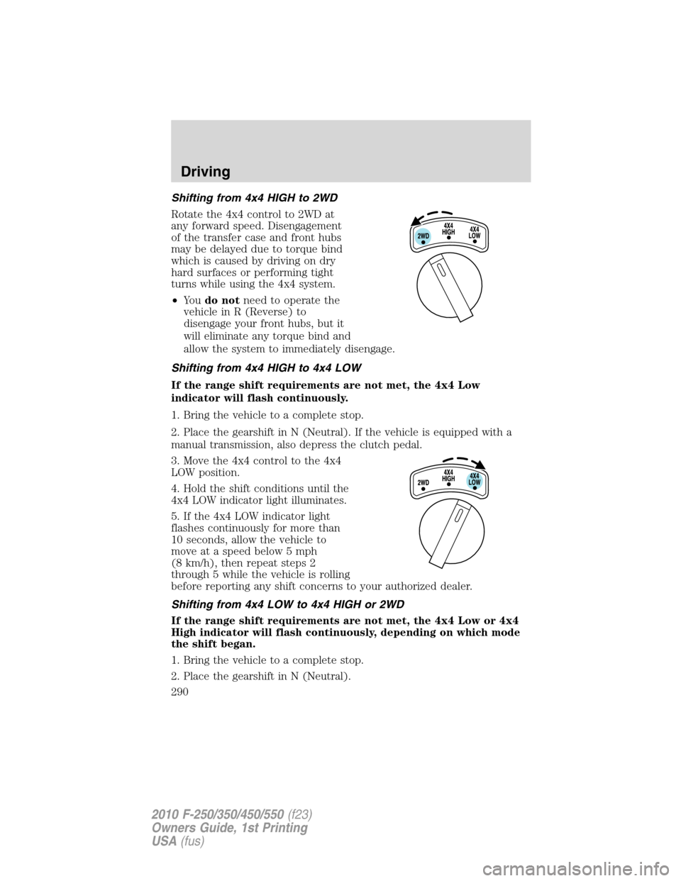
Rotate the 4x4 control to 2WD at
any forward speed. Disengagement
of the transfer case and front hubs
may be delayed due to torque bind
which is caused by driving on dry
hard surfaces or performing tight
turns while using the 4x4 system.
•Yo udo notneed to operate the
vehicle in R (Reverse) to
disengage your front hubs, but it
will eliminate any torque bind and
allow the system to immediately disengage.
Shifting from 4x4 HIGH to 4x4 LOW
If the range shift requirements are not met, the 4x4 Low
indicator will flash continuously.
1. Bring the vehicle to a complete stop.
2. Place the gearshift in N (Neutral). If the vehicle is equipped with a
manual transmission, also depress the clutch pedal.
3. Move the 4x4 control to the 4x4
LOW position.
4. Hold the shift conditions until the
4x4 LOW indicator light illuminates.
5. If the 4x4 LOW indicator light
flashes continuously for more than
10 seconds, allow the vehicle to
move at a speed below 5 mph
(8 km/h), then repeat steps 2
through 5 while the vehicle is rolling
before reporting any shift concerns to your authorized dealer.
Shifting from 4x4 LOW to 4x4 HIGH or 2WD
If the range shift requirements are not met, the 4x4 Low or 4x4
High indicator will flash continuously, depending on which mode
the shift began.
1. Bring the vehicle to a complete stop.
2. Place the gearshift in N (Neutral).
Driving
290
2010 F-250/350/450/550(f23)
Owners Guide, 1st Printing
USA(fus)
Page 325 of 407
15. Remove the lug nuts with the lug wrench.
16. Replace the flat tire with the spare tire, making sure the valve stem
is facing outward on all front an inboard rear wheels. If replacing the
outboard wheel, the valve stem must be facing inward. Reinstall the lug
nuts until the wheel is snug against the hub. Do not fully tighten the lug
nuts until the wheel has been lowered.
17. Lower the wheel by slowly turning the release valve
counterclockwise. Opening the release valve slowly will provide a more
controlled rate of descent.
The following steps apply to all vehicles:
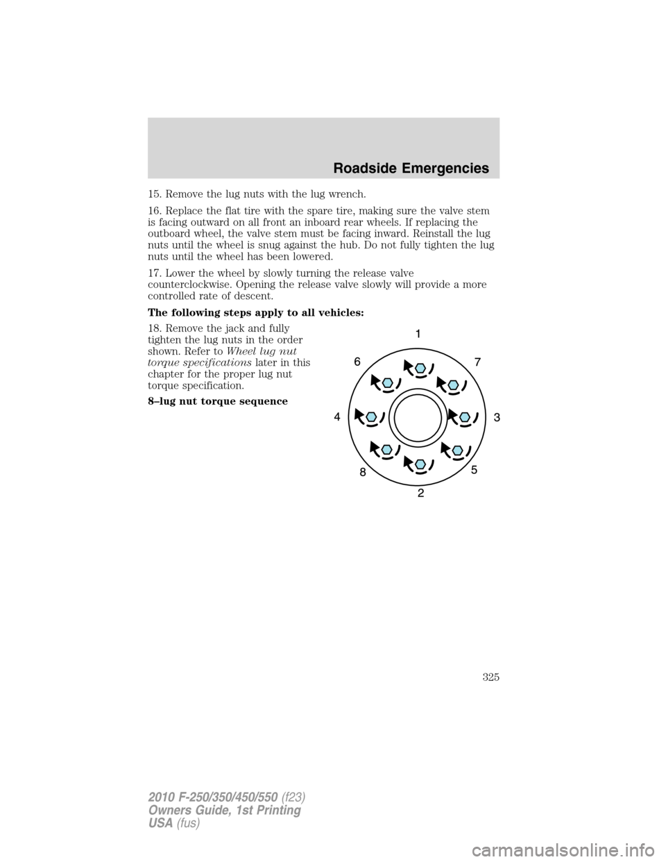
18. Remove the jack and fully
tighten the lug nuts in the order
shown. Refer toWheel lug nut
torque specificationslater in this
chapter for the proper lug nut
torque specification.
8–lug nut torque sequence
Roadside Emergencies
325
2010 F-250/350/450/550(f23)
Owners Guide, 1st Printing
USA(fus)
Page 326 of 407
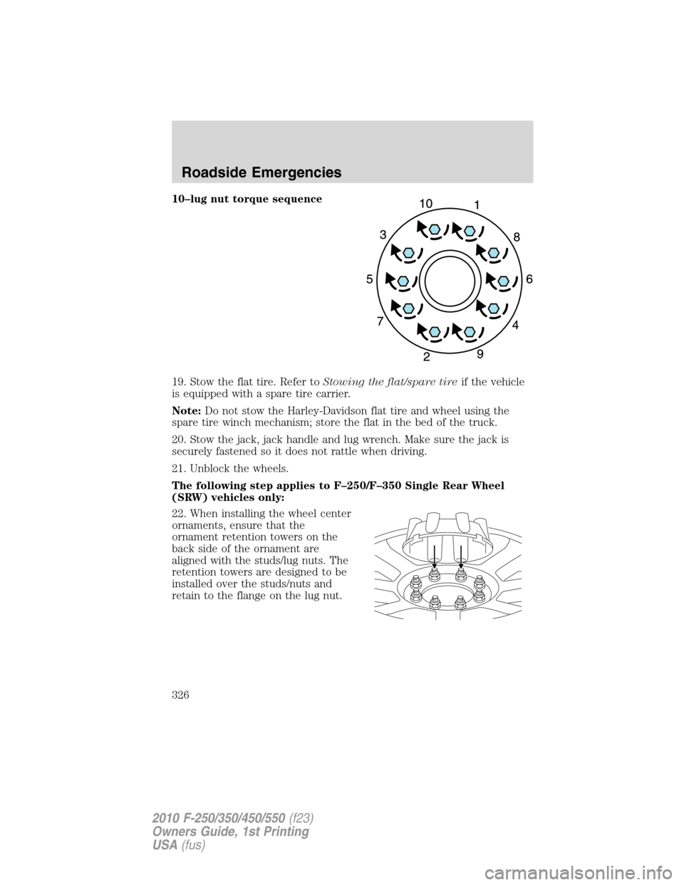
10–lug nut torque sequence
19. Stow the flat tire. Refer toStowing the flat/spare tireif the vehicle
is equipped with a spare tire carrier.
Note:Do not stow the Harley-Davidson flat tire and wheel using the
spare tire winch mechanism; store the flat in the bed of the truck.
20. Stow the jack, jack handle and lug wrench. Make sure the jack is
securely fastened so it does not rattle when driving.
21. Unblock the wheels.
The following step applies to F–250/F–350 Single Rear Wheel
(SRW) vehicles only:
22. When installing the wheel center
ornaments, ensure that the
ornament retention towers on the
back side of the ornament are
aligned with the studs/lug nuts. The
retention towers are designed to be
installed over the studs/nuts and
retain to the flange on the lug nut.
Roadside Emergencies
326
2010 F-250/350/450/550(f23)
Owners Guide, 1st Printing
USA(fus)
Page 329 of 407
5. Repeat this tightness check procedure when servicing the spare tire
pressure (every six months, perscheduled maintenance information),
or at any time that the spare tire is disturbed through service of other
components.
6. If removed, install the spare tire lock (if equipped) into the bumper
drive tube with the spare tire lock key (if equipped) and jack handle.
WHEEL LUG NUT TORQUE SPECIFICATIONS
On vehicles equipped with single rear wheels, retighten the lug nuts to
the specified torque at 500 miles (800 km) after any wheel disturbance
(tire rotation, changing a flat tire, wheel removal, etc.).
On vehicles equipped with dual rear wheels, retighten the wheel lug nuts
to the specified torque at 100 miles (160 km), and again at 500 miles
(800 km) of new vehicle operation and after any wheel disturbance (tire
rotation, changing a flat tire, wheel removal, etc.).
Bolt size Wheel lug nut torque*
lb.ft. N•m
M14 x 1.5 165 224
* Torque specifications are for nut and bolt threads free of dirt and
rust. Use only Ford recommended replacement fasteners.
It is important to follow the proper wheel mounting and lug nut torque
procedures.
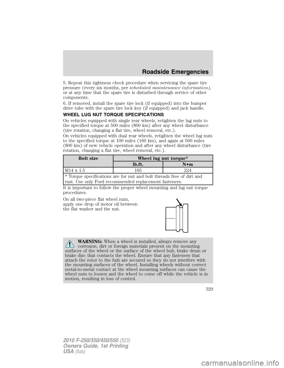
On all two-piece flat wheel nuts,
apply one drop of motor oil between
the flat washer and the nut.
WARNING:When a wheel is installed, always remove any
corrosion, dirt or foreign materials present on the mounting
surfaces of the wheel or the surface of the wheel hub, brake drum or
brake disc that contacts the wheel. Ensure that any fasteners that
attach the rotor to the hub are secured so they do not interfere with
the mounting surfaces of the wheel. Installing wheels without correct
metal-to-metal contact at the wheel mounting surfaces can cause the
wheel nuts to loosen and the wheel to come off while the vehicle is in
motion, resulting in loss of control.
Roadside Emergencies
329
2010 F-250/350/450/550(f23)
Owners Guide, 1st Printing
USA(fus)