Page 299 of 407
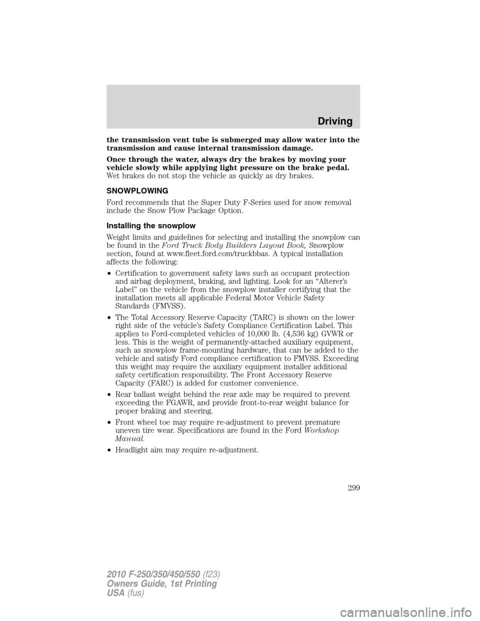
the transmission vent tube is submerged may allow water into the
transmission and cause internal transmission damage.
Once through the water, always dry the brakes by moving your
vehicle slowly while applying light pressure on the brake pedal.
Wet brakes do not stop the vehicle as quickly as dry brakes.
SNOWPLOWING
Ford recommends that the Super Duty F-Series used for snow removal
include the Snow Plow Package Option.
Installing the snowplow
Weight limits and guidelines for selecting and installing the snowplow can
be found in theFord Truck Body Builders Layout Book,Snowplow
section, found at www.fleet.ford.com/truckbbas. A typical installation
affects the following:
•Certification to government safety laws such as occupant protection
and airbag deployment, braking, and lighting. Look for an “Alterer’s
Label” on the vehicle from the snowplow installer certifying that the
installation meets all applicable Federal Motor Vehicle Safety
Standards (FMVSS).
•The Total Accessory Reserve Capacity (TARC) is shown on the lower
right side of the vehicle’s Safety Compliance Certification Label. This
applies to Ford-completed vehicles of 10,000 lb. (4,536 kg) GVWR or
less. This is the weight of permanently-attached auxiliary equipment,
such as snowplow frame-mounting hardware, that can be added to the
vehicle and satisfy Ford compliance certification to FMVSS. Exceeding
this weight may require the auxiliary equipment installer additional
safety certification responsibility. The Front Accessory Reserve
Capacity (FARC) is added for customer convenience.
•Rear ballast weight behind the rear axle may be required to prevent
exceeding the FGAWR, and provide front-to-rear weight balance for
proper braking and steering.
•Front wheel toe may require re-adjustment to prevent premature
uneven tire wear. Specifications are found in the FordWorkshop
Manual.
•Headlight aim may require re-adjustment.
Driving
299
2010 F-250/350/450/550(f23)
Owners Guide, 1st Printing
USA(fus)
Page 301 of 407
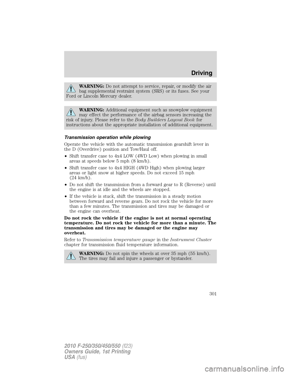
WARNING:Do not attempt to service, repair, or modify the air
bag supplemental restraint system (SRS) or its fuses. See your
Ford or Lincoln Mercury dealer.
WARNING:Additional equipment such as snowplow equipment
may effect the performance of the airbag sensors increasing the
risk of injury. Please refer to theBody Builders Layout Bookfor
instructions about the appropriate installation of additional equipment.
Transmission operation while plowing
Operate the vehicle with the automatic transmission gearshift lever in
the D (Overdrive) position and Tow/Haul off.
•Shift transfer case to 4x4 LOW (4WD Low) when plowing in small
areas at speeds below 5 mph (8 km/h).
•Shift transfer case to 4x4 HIGH (4WD High) when plowing larger
areas or light snow at higher speeds. Do not exceed 15 mph
(24 km/h).
•Do not shift the transmission from a forward gear to R (Reverse) until
the engine is at idle and the wheels are stopped.
•If the vehicle is stuck, shift the transmission in a steady motion
between forward and reverse gears. Do not rock the vehicle for more
than a few minutes. The transmission and tires may be damaged or
the engine can overheat.
Do not rock the vehicle if the engine is not at normal operating
temperature. Do not rock the vehicle for more than a minute. The
transmission and tires may be damaged or the engine may
overheat.
Refer toTransmission temperature gaugein theInstrument Cluster
chapter for transmission fluid temperature information.
WARNING:Do not spin the wheels at over 35 mph (55 km/h).
The tires may fail and injure a passenger or bystander.
Driving
301
2010 F-250/350/450/550(f23)
Owners Guide, 1st Printing
USA(fus)
Page 307 of 407
The fuses are coded as follows.
Fuse/Relay
LocationFuse Amp
RatingProtected Circuits
1 30A Not used (spare)
2 15A Not used (spare)
3 15A Family entertainment system (FES)
4 30A Not used (spare)
5 10A Keypad illumination, Brake-shift
interlock (BSI), SPBJB
6 20A Turn signals
7 10A Left headlamp (Low beam)
8 10A Right headlamp (Low beam)
9 15A Interior lighting, Lighted running
boards
10 15A Cargo lamp, Puddle lamp, Switch
backlight
Roadside Emergencies
307
2010 F-250/350/450/550(f23)
Owners Guide, 1st Printing
USA(fus)
Page 308 of 407
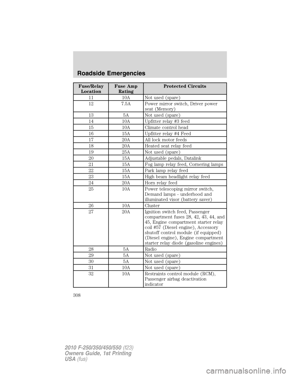
Fuse/Relay
LocationFuse Amp
RatingProtected Circuits
11 10A Not used (spare)
12 7.5A Power mirror switch, Driver power
seat (Memory)
13 5A Not used (spare)
14 10A Upfitter relay #3 feed
15 10A Climate control head
16 15A Upfitter relay #4 Feed
17 20A All lock motor feeds
18 20A Heated seat relay feed
19 25A Not used (spare)
20 15A Adjustable pedals, Datalink
21 15A Fog lamp relay feed, Cornering lamps
22 15A Park lamp relay feed
23 15A High beam headlight relay feed
24 20A Horn relay feed
25 10A Power telescoping mirror switch,
Demand lamps - underhood and
illuminated visor (battery saver)
26 10A Cluster
27 20A Ignition switch feed, Passenger
compartment fuses 28, 42, 43, 44, and
45, Engine compartment starter relay
coil #57 (Diesel engine), Accessory
shutoff control module (if equipped)
(Diesel engine), Engine compartment
starter relay diode (gasoline engines)
28 5A Radio
29 5A Not used (spare)
30 5A Not used (spare)
31 10A Not used (spare)
32 10A Restraints control module (RCM),
Passenger airbag deactivation
indicator
Roadside Emergencies
308
2010 F-250/350/450/550(f23)
Owners Guide, 1st Printing
USA(fus)
Page 311 of 407
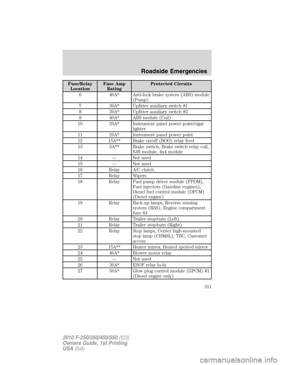
Fuse/Relay
LocationFuse Amp
RatingProtected Circuits
6 40A* Anti-lock brake system (ABS) module
(Pump)
7 30A* Upfitter auxiliary switch #1
8 30A* Upfitter auxiliary switch #2
9 40A* ABS module (Coil)
10 20A* Instrument panel power point/cigar
lighter
11 20A* Instrument panel power point
12 15A** Brake on/off (BOO) relay feed
13 5A** Brake switch, Brake switch relay coil,
SJB module, 4x4 module
14 — Not used
15 — Not used
16 Relay A/C clutch
17 Relay Wipers
18 Relay Fuel pump driver module (FPDM),
Fuel injectors (Gasoline engines),
Diesel fuel control module (DFCM)
(Diesel engine)
19 Relay Back-up lamps, Reverse sensing
system (RSS), Engine compartment
fuse 63
20 Relay Trailer stop/turn (Left)
21 Relay Trailer stop/turn (Right)
22 Relay Stop lamps, Center high-mounted
stop lamp (CHMSL), TBC, Customer
access
23 15A** Heater mirror, Heated spotted mirror
24 40A* Blower motor relay
25 — Not used
26 30A* ESOF relay lo-hi
27 50A* Glow plug control module (GPCM) #1
(Diesel engine only)
Roadside Emergencies
311
2010 F-250/350/450/550(f23)
Owners Guide, 1st Printing
USA(fus)
Page 316 of 407
3.Full-size dissimilar spare without label on wheel
When driving with the full-size dissimilar spare tire/wheel,do not:
•Exceed 70 mph (113 km/h)
•Use more than one dissimilar spare tire/wheel at a time
•Use commercial car washing equipment
•Use snow chains on the end of the vehicle with the dissimilar spare
tire/wheel
The usage of a full-size dissimilar spare tire/wheel can lead to
impairment of the following:
•Handling, stability and braking performance
•Comfort and noise
•Ground clearance and parking at curbs
•Winter weather driving capability
•Wet weather driving capability
•All-Wheel driving capability (if applicable)
•Load leveling adjustment (if applicable)
When driving with the full-size dissimilar spare tire/wheel additional
caution should be given to:
•Towing a trailer
•Driving vehicles equipped with a camper body
•Driving vehicles with a load on the cargo rack
Drive cautiously when using a full-size dissimilar spare tire/wheel and
seek service as soon as possible.
Spare tire information
Note:If your vehicle is equipped the tire pressure monitoring system
(TPMS), the system indicator light will illuminate when the spare is in
use. To restore the full functionality of the TPMS system, all road wheels
equipped with the tire pressure monitoring sensors must be mounted on
the vehicle.
If your vehicle is equipped with TPMS, have a flat tire serviced by an
authorized dealer in order to prevent damage to the TPMS sensor; refer
toTire Pressure Monitoring System (TPMS)in theTires, Wheel and
Loadingchapter. Replace the spare tire with the road tire as soon as
possible.
Roadside Emergencies
316
2010 F-250/350/450/550(f23)
Owners Guide, 1st Printing
USA(fus)
Page 319 of 407
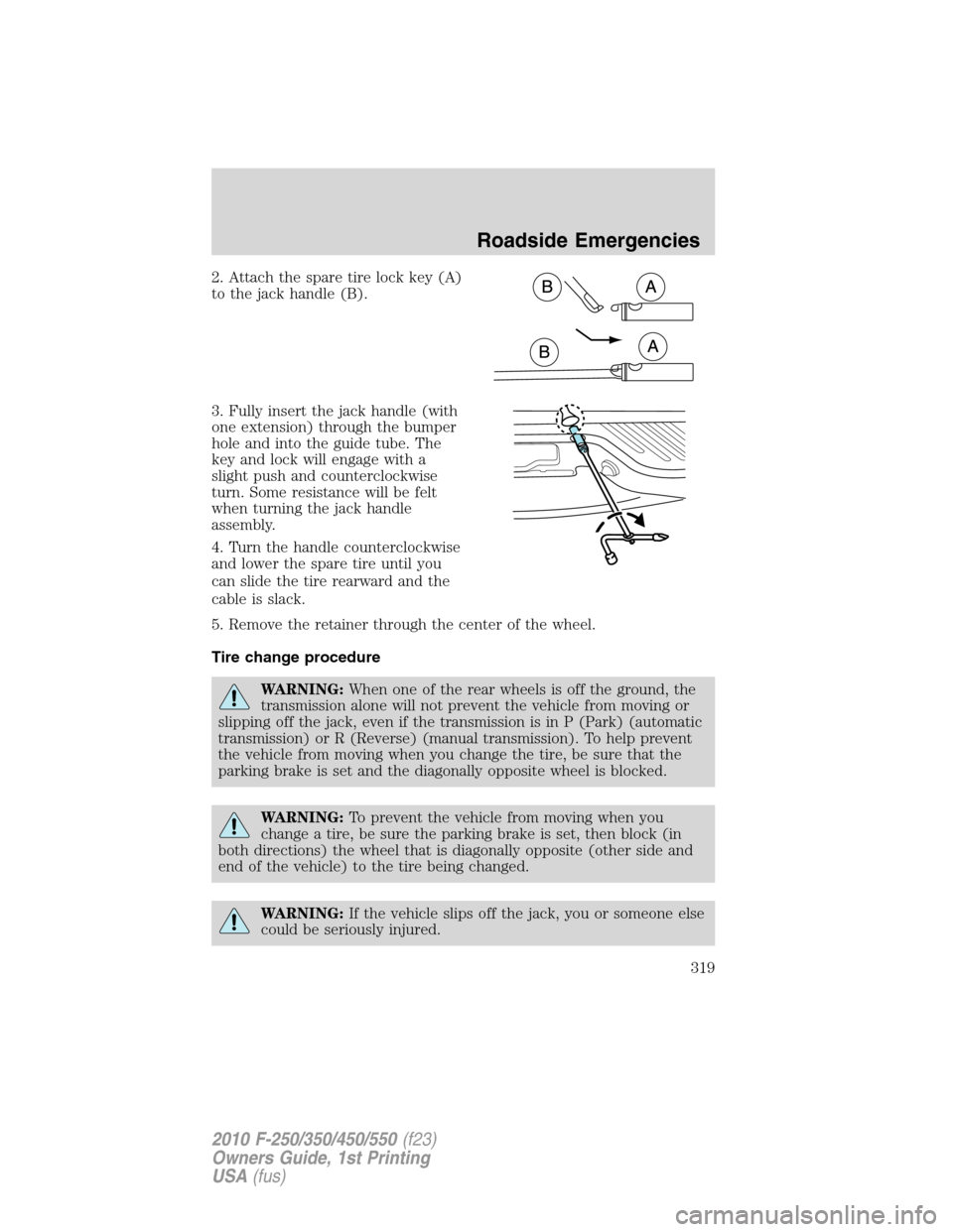
2. Attach the spare tire lock key (A)
to the jack handle (B).
3. Fully insert the jack handle (with
one extension) through the bumper
hole and into the guide tube. The
key and lock will engage with a
slight push and counterclockwise
turn. Some resistance will be felt
when turning the jack handle
assembly.
4. Turn the handle counterclockwise
and lower the spare tire until you
can slide the tire rearward and the
cable is slack.
5. Remove the retainer through the center of the wheel.
Tire change procedure
WARNING:When one of the rear wheels is off the ground, the
transmission alone will not prevent the vehicle from moving or
slipping off the jack, even if the transmission is in P (Park) (automatic
transmission) or R (Reverse) (manual transmission). To help prevent
the vehicle from moving when you change the tire, be sure that the
parking brake is set and the diagonally opposite wheel is blocked.
WARNING:To prevent the vehicle from moving when you
change a tire, be sure the parking brake is set, then block (in
both directions) the wheel that is diagonally opposite (other side and
end of the vehicle) to the tire being changed.
WARNING:If the vehicle slips off the jack, you or someone else
could be seriously injured.
Roadside Emergencies
319
2010 F-250/350/450/550(f23)
Owners Guide, 1st Printing
USA(fus)
Page 331 of 407
4. Check all battery terminals and remove any excessive corrosion before
you attach the battery cables. Ensure that vent caps are tight and level.
5. Turn the heater fan on in both vehicles to protect from any electrical
surges. Turn all other accessories off.
Connecting the jumper cables
1. Connect the positive (+) jumper cable to the positive (+) terminal of
the discharged battery.
Note:In the illustrations,lightning boltsare used to designate the
assisting (boosting) battery.
2. Connect the other end of the positive (+) cable to the positive (+)
terminal of the assisting battery.
+–+–
+–+–
Roadside Emergencies
331
2010 F-250/350/450/550(f23)
Owners Guide, 1st Printing
USA(fus)