2010 FORD F750 ignition
[x] Cancel search: ignitionPage 100 of 274

Parking brake
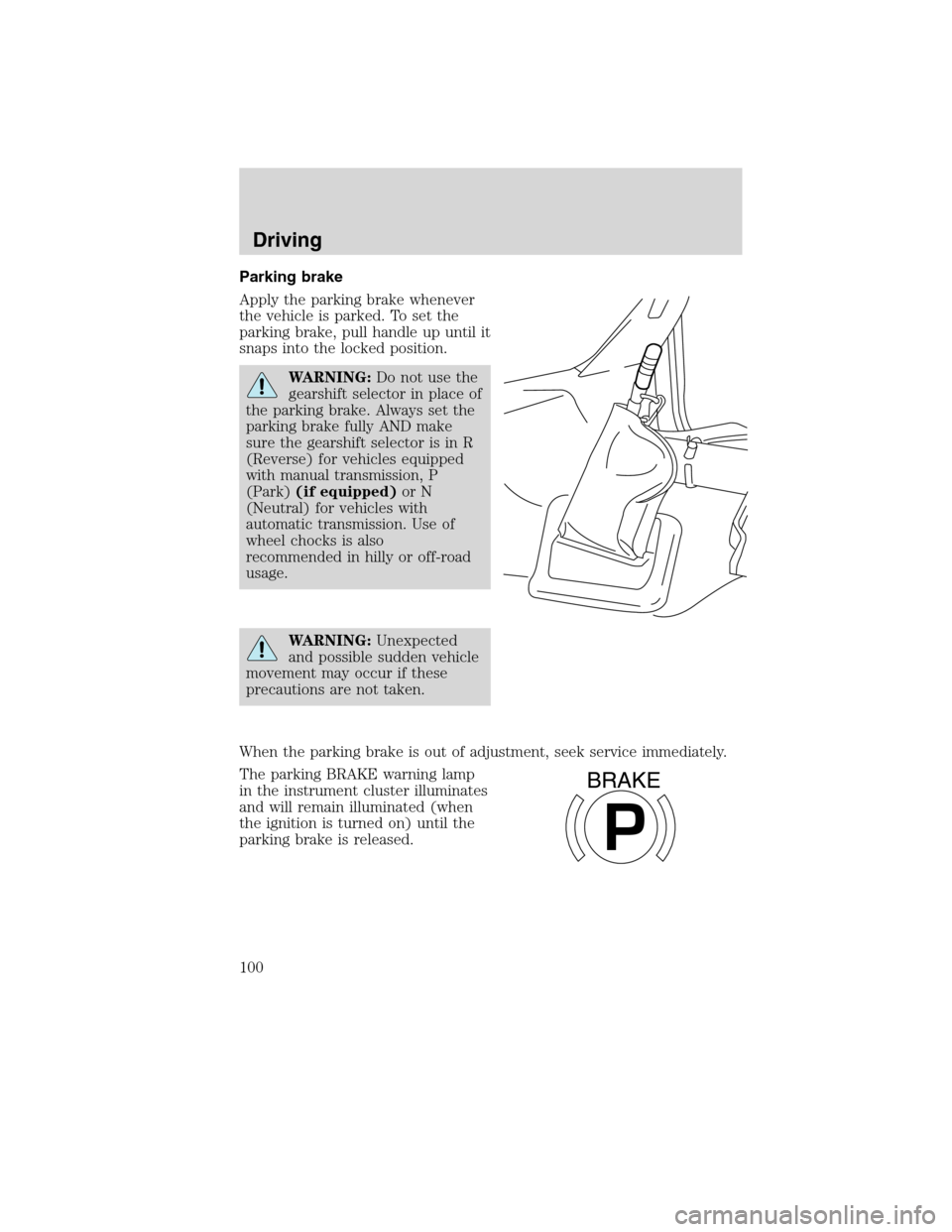
Apply the parking brake whenever
the vehicle is parked. To set the
parking brake, pull handle up until it
snaps into the locked position.
WARNING:Do not use the
gearshift selector in place of
the parking brake. Always set the
parking brake fully AND make
sure the gearshift selector is in R
(Reverse) for vehicles equipped
with manual transmission, P
(Park)(if equipped)or N
(Neutral) for vehicles with
automatic transmission. Use of
wheel chocks is also
recommended in hilly or off-road
usage.
WARNING:Unexpected
and possible sudden vehicle
movement may occur if these
precautions are not taken.
When the parking brake is out of adjustment, seek service immediately.
The parking BRAKE warning lamp
in the instrument cluster illuminates
and will remain illuminated (when
the ignition is turned on) until the
parking brake is released.
P
BRAKE
Driving
100
2010 F-650/750(f67)
Supplement(supplement), 1st Printing
USA(fus)
Page 105 of 274

Periodically check the air pressure
gauge while driving. Pressure should
range between approximately
100–125 psi (690–862 kPa). The air
compressor governor cut-in and
cut-out pressure settings are preset
at the factory and are not
adjustable.
When air pressure is insufficient
(below 60 psi [414 kPa]), a warning
light illuminates and a buzzer
sounds when the ignition is in the
on position.
This condition may be caused by excessive brake applications depleting
the system air pressure. If this condition occurs, stop driving the vehicle
until the compressor has fully recharged the air system.
WARNING:Do not move the vehicle when the air pressure is
insufficient because the brake system may be inoperative.
Select a gear ratio to help slow your vehicle before descending grades.
Supplement with brakes as required to safely slow the vehicle and avoid
overspeeding the engine.
Air chamber stroke indication
Air chamber push rods have orange stroke indicator markers that warn
when the braking system requires adjustment or repair. The orange
stripe is painted on the air chamber push rod at the slack adjuster stroke
dimension which requires service when visible during brake application.
Air brake inspection and adjustment or repairs should be performed by a
qualified service technician in accordance with the instructions in the
service manual.
Driving
105
2010 F-650/750(f67)
Supplement(supplement), 1st Printing
USA(fus)
Page 108 of 274

Parking brake control (knob)
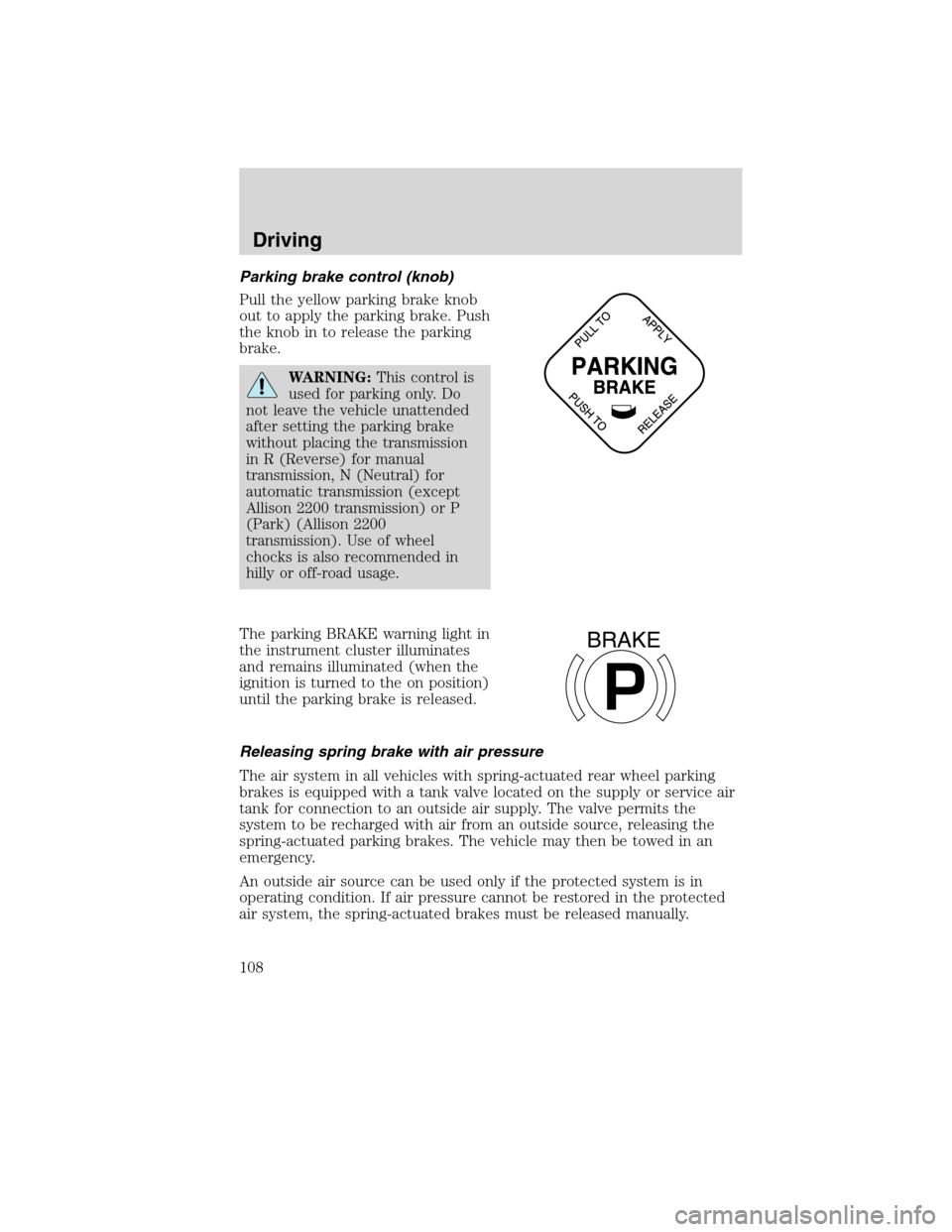
Pull the yellow parking brake knob
out to apply the parking brake. Push
the knob in to release the parking
brake.
WARNING:This control is
used for parking only. Do
not leave the vehicle unattended
after setting the parking brake
without placing the transmission
in R (Reverse) for manual
transmission, N (Neutral) for
automatic transmission (except
Allison 2200 transmission) or P
(Park) (Allison 2200
transmission). Use of wheel
chocks is also recommended in
hilly or off-road usage.
The parking BRAKE warning light in
the instrument cluster illuminates
and remains illuminated (when the
ignition is turned to the on position)
until the parking brake is released.
Releasing spring brake with air pressure
The air system in all vehicles with spring-actuated rear wheel parking
brakes is equipped with a tank valve located on the supply or service air
tank for connection to an outside air supply. The valve permits the
system to be recharged with air from an outside source, releasing the
spring-actuated parking brakes. The vehicle may then be towed in an
emergency.
An outside air source can be used only if the protected system is in
operating condition. If air pressure cannot be restored in the protected
air system, the spring-actuated brakes must be released manually.
P
BRAKE
Driving
108
2010 F-650/750(f67)
Supplement(supplement), 1st Printing
USA(fus)
Page 118 of 274

ANTI-LOCK BRAKE SYSTEM (ABS)
A noise from the hydraulic pump motor and pulsation in the pedal may
be observed during ABS braking events. Pedal pulsation coupled with
noise while braking under panic conditions or on loose gravel, bumps,
wet or snowy roads is normal and indicates proper functioning of the
vehicle’s ABS. If the vehicle has continuous vibration or shudder in the
steering wheel while braking, the vehicle should be inspected by a
qualified service technician.
The ABS operates by detecting the
onset of wheel lockup during brake
applications and compensating for
this tendency. The wheels are
prevented from locking even when
the brakes are firmly applied. The
accompanying illustration depicts
the advantage of an ABS-equipped
vehicle (on bottom) to a non-ABS
equipped vehicle (on top) during hard braking with loss of front braking
traction.
ABS warning light
The
ABSwarning light in the instrument cluster momentarily illuminates
when the ignition is turned on and the engine is off. If the light does not
illuminate momentarily at start up, remains on after the vehicle reaches
5–10 mph (8–16 km/h), or continues to flash, the ABS needs to be
serviced.
With the ABS light on, the anti-lock brake system is disabled and normal
braking is still effective unless the brake warning light also remains
illuminated. (If your parking brake warning light illuminates, have your
vehicle serviced immediately.)
Using ABS
•In an emergency or when maximum efficiency from the ABS is
required, apply continuous full force on the brake. The ABS will be
activated immediately, thus allowing you to retain full steering control
of your vehicle and, providing there is sufficient space, will enable you
to avoid obstacles and bring the vehicle to a controlled stop.
•The ABS does not decrease the time necessary to apply the brakes or
always reduce stopping distance. Always leave enough room between
your vehicle and the vehicle in front of you to stop.
Driving
118
2010 F-650/750(f67)
Supplement(supplement), 1st Printing
USA(fus)
Page 119 of 274

•We recommend that you familiarize yourself with this braking
technique. However, avoid taking any unnecessary risks.
TRACTION CONTROL™ (IF EQUIPPED)
Your vehicle may be equipped with a Traction Control™ system. This
system helps you maintain the stability and steerability of your vehicle,
especially on slippery road surfaces such as snow- or ice-covered roads
and gravel roads, by reducing engine power and/or selectively applying
the rear brakes. The system will allow your vehicle to make better use of
available traction in these conditions.
Note:The traction control system will not apply the brakes when the
vehicle speed is above 25 mph (40 km/h).
During Traction Control™ operation,
the traction control light in the
instrument cluster will flash rapidly
and the engine will not “rev-up”
when you press further on the
accelerator. This is normal system behavior and should be no reason for
concern. If the traction control light does not flash during a traction
control event or stays illuminated, the system is not functioning properly,
take your vehicle to your dealer for service.
When the Traction Control™ switch,
located on the instrument panel, is
activated standard Traction
Control™ will change to Off Road or
Mud/Snow traction mode, the
traction control light will be
illuminated and flash slowly. If a
traction event occurs, in either
mode the traction control light will
flash rapidly. The standard Traction
Control™ can be selected by
pressing the Traction Control™ switch again or will be automatically
selected at next ignition cycle.
If you should become stuck in snow or ice or on a very slippery road
surface, try switching to the Off Road or Mud/Snow Traction Control™
mode. This may allow excess wheel spin to “dig” the vehicle out and
enable a successful “rocking” maneuver.
Driving
119
2010 F-650/750(f67)
Supplement(supplement), 1st Printing
USA(fus)
Page 120 of 274

WARNING:Aggressive driving in any road conditions can cause
you to lose control of your vehicle increasing the risk of severe
personal injury or property damage. The occurrence of a Traction
Control™ event is an indication that at least some of the tires have
exceeded their ability to grip the road; this may lead to an increased
risk of loss of vehicle control, vehicle rollover, personal injury and
death. If you experience a severe road event, SLOW DOWN.
AIR SUSPENSION (IF EQUIPPED)
Note:The vehicle must not be operated without air in the suspension
springs. Operating the vehicle without air in the air suspension springs
will damage the suspension, degrade ride performance and may cause
property damage.
The suspension system automatically adjusts to different loads to
maintain a constant frame height. The system allows for ease of vehicle
loading and provides improved vehicle ride and increased driver comfort.
Air suspension dump switch
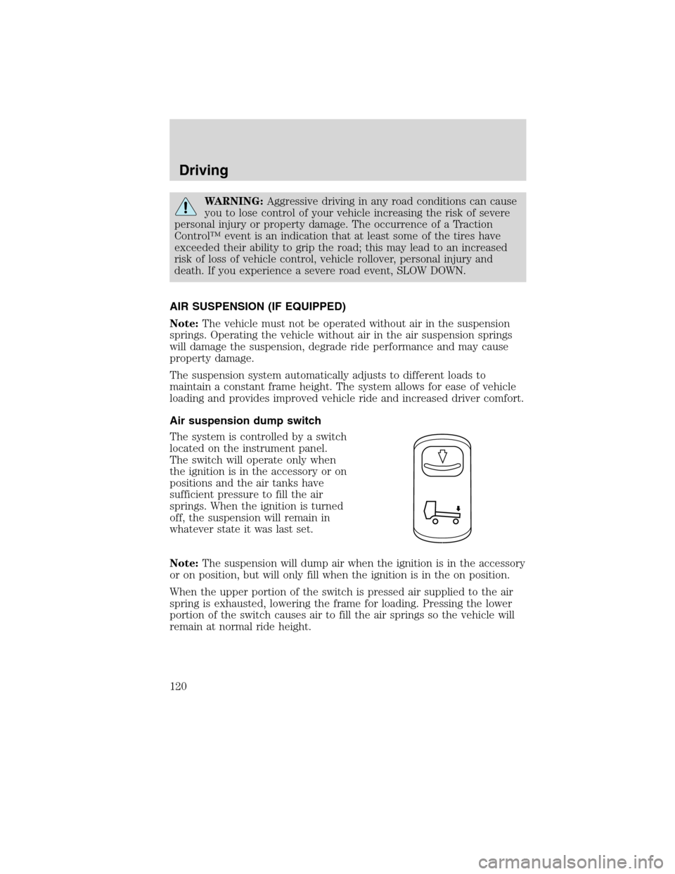
The system is controlled by a switch
located on the instrument panel.
The switch will operate only when
the ignition is in the accessory or on
positions and the air tanks have
sufficient pressure to fill the air
springs. When the ignition is turned
off, the suspension will remain in
whatever state it was last set.
Note:The suspension will dump air when the ignition is in the accessory
or on position, but will only fill when the ignition is in the on position.
When the upper portion of the switch is pressed air supplied to the air
spring is exhausted, lowering the frame for loading. Pressing the lower
portion of the switch causes air to fill the air springs so the vehicle will
remain at normal ride height.
Driving
120
2010 F-650/750(f67)
Supplement(supplement), 1st Printing
USA(fus)
Page 143 of 274

HAZARD FLASHER
The hazard flasher control is located
on the steering column, just behind
the steering wheel. The hazard
flashers will operate when the
ignition is off.
Press the flasher control and all
front and rear direction signals will
flash. Press the flasher control again
to turn them off. Use it when your
vehicle is disabled and is creating a
safety hazard for other motorists.
Note:With extended use, the flasher may run down your battery.
FUSING
If electrical components in the vehicle are not working, a fuse may have
blown. Blown fuses are identified by a broken wire within the fuse.
Check the appropriate fuses before replacing any electrical components.
Note:Always replace a fuse with one that has the specified amperage
rating. Using a fuse with a higher amperage rating can cause severe wire
damage and could start a fire.
Roadside Emergencies
143
2010 F-650/750(f67)
Supplement(supplement), 1st Printing
USA(fus)
Page 146 of 274

Power distribution box
WARNING:Always disconnect the battery before servicing high
current fuses.
WARNING:To reduce risk of electrical shock, always replace
the cover to the Power Distribution Box before reconnecting the
battery or refilling fluid reservoirs.
Fuse/Relay
LocationFuse Amp
RatingFuse Description
1 15A* Main light switch
2 30A* Power seat (driver)
3 30A* Power seat (passenger)
4 15A* Windshield washer relay, Washer pump motor
5 5A* Brake warning switch
6 15A* Air intake heater (Caterpillar engine only)
7 15A* Brake pressure switches, Stoplamp relay
8 25A* Fuel heater relay
9 20A* Ignition switch, Starter cutoff
10 15A* Air tank moisture removal valve
503
502
501304
303
302 301
2119 22 2024
23401
207 201202 203204
209 206
208 205602
601118114
110106
102
117 113 109105
101
116 112 108104
115 111 107103
18 16
14 12 10 864
2
17 15
13 11 9 753
1
Roadside Emergencies
146
2010 F-650/750(f67)
Supplement(supplement), 1st Printing
USA(fus)