2010 FORD F750 ECU
[x] Cancel search: ECUPage 155 of 274

4. Remove the jumper cable from the positive (+) terminal of the
disabled vehicle’s battery.
After the disabled vehicle has been started and the jumper cables
removed, allow it to idle for several minutes so the engine computer can
relearnits idle conditions.
WRECKER TOWING INSTRUCTIONS
Before moving the disabled vehicle, check for adequate road clearance of
vehicle components. It is recommended the disabled vehicle be unloaded
prior to being towed to reduce any abnormal load to the vehicle
components resulting from the towing procedures. Before towing, be
sure to fully release the parking brake. The spring-actuated type parking
brake can be reset by recharging the air system with at least 64 psi
(441 kPa) of air. If the brake system will not retain air pressure, then the
spring brakes must be released manually. Refer toParking brakein the
Drivingchapter
Note:For towing, make sure the vehicle is securely connected to the
tow vehicle and the tow vehicle parking brakes are applied before
releasing the disabled vehicle’s spring brakes.
WARNING:To reduce the risk of personal injury or property
damage when manually releasing the spring brakes, be sure to
block the wheels so the vehicle cannot move once the brakes are
released.
Towing the vehicle with the front wheels suspended
When it is necessary to tow a vehicle with the front wheels suspended,
extra precautions must be taken to avoid transmission or differential
damage. Proceed as follows:
•Remove the axle shafts from the axle assembly to prevent the wheels
from driving the differential and the transmission.
+–+–
Roadside Emergencies
155
2010 F-650/750(f67)
Supplement(supplement), 1st Printing
USA(fus)
Page 156 of 274

•The wheel hub ends must be covered to prevent loss of axle lubricant
and entrance of other contaminants. If the axle shafts are not
removed, removal of the driveshaft is required.
Note:To avoid transmission damage, vehicles should not be towed even
a short distance without suspending rear wheels or removing the axle
shaft or driveshaft.
Note:In the event the chassis is equipped with a tandem axle and the
vehicle is to be towed from the front, the forward rear axle may be
raised to clear the road surface and secured to the frame by chains or
U-bolts, allowing only the rear rear axle to contact the road surface. Axle
shafts must be removed from the rear rear axle assembly. The wheel hub
ends must be covered to prevent loss of axle lubricant and entrance of
contaminants. Use extreme care in securing the chains or U-bolts to
avoid possible damage to the brake lines, hoses or other components.
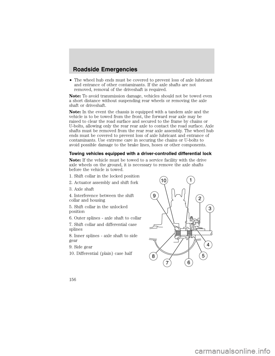
Towing vehicles equipped with a driver-controlled differential lock
Note:If the vehicle must be towed to a service facility with the drive
axle wheels on the ground, it is necessary to remove the axle shafts
before the vehicle is towed.
1. Shift collar in the locked position
2. Actuator assembly and shift fork
3. Axle shaft
4. Interference between the shift
collar and housing
5. Shift collar in the unlocked
position
6. Outer splines - axle shaft to collar
7. Shift collar and differential case
splines
8. Inner splines - axle shaft to side
gear
9. Side gear
10. Differential (plain) case half
Roadside Emergencies
156
2010 F-650/750(f67)
Supplement(supplement), 1st Printing
USA(fus)
Page 161 of 274

In the case of 1 or 2 above, the consumer must also notify the
manufacturer of the need for the repair of the nonconformity at the
following address:
Ford Motor Company
16800 Executive Plaza Drive
Mail Drop 3NE-B
Dearborn, MI 48126
GETTING ASSISTANCE OUTSIDE THE U.S AND CANADA
Before exporting your vehicle to a foreign country, contact the
appropriate foreign embassy or consulate. These officials can inform you
of local vehicle registration regulations and where to find diesel fuel.
If you cannot find diesel fuel or can only get fuel with an anti-knock
index lower than is recommended for your vehicle, contact a regional
office or owner relations/customer relationship office.
The use of low quality diesel fuel may affect your emissions control
system and may cause engine damage. Ford Motor Company/Ford of
Canada is not responsible for any damage caused by use of improper
fuel. In the United States, using leaded fuel may also result in difficulty
importing your vehicle back into the U.S.
Ford dealerships outside of the US & Canada may be unable to support
the F–650/750 due to the specialized training and servicing requirements
of these vehicles. If your vehicle must be serviced while you are traveling
or living in Central or South America, the Caribbean, or the Middle East,
contact the nearest Ford dealership. If the dealership cannot help you,
write or call:
FORD MOTOR COMPANY
FORD EXPORT OPERATIONS
1555 Fairlane Drive
Fairlane Business Park #3
Allen Park, Michigan 48101
U.S.A.
Telephone: (313) 594-4857
FAX: (313) 390-0804
If you are in another foreign country, contact the nearest Ford
dealership. If the dealership employees cannot help you, they can direct
you to the nearest Ford affiliate office.
If you buy your vehicle in North America and then relocate outside of
the U.S. or Canada, register your vehicle identification number (VIN) and
new address with Ford Motor Company Export Operations.
Customer Assistance
161
2010 F-650/750(f67)
Supplement(supplement), 1st Printing
USA(fus)
Page 171 of 274

Check to make sure that the axle mounting U-bolt nuts, attaching or
mounting bolts and nuts are securely tightened. Regularly check front
axle for damage, binding, worn parts and adequate lubrication.
At regular intervals, or during other scheduled maintenance, (tire
rotation/service, wheel bearing service, alignment, etc.) the kingpins
should be checked for excessive wear. Refer to the service manual for
proper procedures.
Toe-in setting - general inspection
Inspecting steer axle tires in the first 3,000–10,000 service miles
(4,800–16,000 service km) will generally show if tires are wearing
normally.
Rapid outside shoulder wear on both tires indicates too much toe-in.
Rapid inside shoulder wear on both tires indicates too much toe-out. In
P&D-type service, left-to-right steer tire tread life differentials up to 40%
can be observed depending on routes and other variables.
Follow the tire manufacturer’s recommended cold inflation pressure for
the tire size, load range (ply rating) and steer axle loading typical for
their operation (each steer axle tire will equal
1�2steer axle loading).
Special applications may warrant a setting based on past experience with
the type of tire operating loads and conditions. Radial tires are more
sensitive to toe-in setting than bias ply tires. While not insensitive to
vehicle alignment, fine tuning school bus alignment to line-haul truck
standards will not drastically improve tire tread life.
It is essential that correct toe-in and tire pressure be maintained for
optimum tire wear.
Rear axle - general inspection
Check to make sure that the axle mounting U-bolts, attaching or
mounting bolts and nuts are securely tightened. Refer toU-bolt nut
torquein this chapter. Regularly check the rear axle for damaged,
binding or worn parts.
NoSpin Detroit Locker positive locking differential
Vehicles equipped with this type differential have the operator’s manual
supplied with the vehicle. Refer to this manual for maintenance checks.
Maintenance and Specifications
171
2010 F-650/750(f67)
Supplement(supplement), 1st Printing
USA(fus)
Page 196 of 274

5. Reinstall the dipstick. Remove it again and check the fluid level.
•If the fluid temperature is at
approximately 68°-120°F
(20°-49°C) (fluid cool or warm
to the touch), check the COLD
side of the dipstick. The fluid
level should be within the FULL
range
•If the fluid level is below the ADD
line, add fluid in small amounts, continuously checking the level until
it reaches the proper level.
•If the fluid temperature is at
approximately 176°–230°F
(80°-110°C) (fluid too hot to
touch), check the HOT side of
the dipstick. The fluid level
should be within the FULL range.
•If the fluid level is below the ADD
line, add fluid in small amounts,
continuously checking the level until it reaches the proper level.
Note:The fluid level may also be checked by looking at the see-through
plastic reservoir. Make sure that the fluid is within the minimum and
maximum fluid range as marked on the reservoir.
A low fluid level may indicate a leak in the power steering system.
Inspect the power steering system and repair the leak. If necessary, see
your dealer or a qualified service technician.
To avoid damage to the power steering system,do notoperate the
vehicle with a low power steering fluid level.
Whenever the dipstick is installed, make sure it is properly seated and
tightened securely.
BRAKE FLUID
Check and refill the Full Power brake fluid reservoir using the following
procedure. Refer to theScheduled Maintenance Guidechapter for the
service interval.
1. Clean the reservoir caps before removal to prevent dirt or water from
entering the reservoir.
ADD MAX. COLDFULL
ADD MAX. HOTFULL
Maintenance and Specifications
196
2010 F-650/750(f67)
Supplement(supplement), 1st Printing
USA(fus)
Page 200 of 274

Eaton UltraShift (if equipped)
The Eaton UltraShift transmission is filled with synthetic fluid from the
factory with no scheduled lube change intervals. This fluid is intended to
last the life of the transmission. However, the system should be checked
regularly to ensure that proper transmission fluid levels remain constant.
Refer to theEaton Driver Instructions Manualfor details.
Manual transmission fluid
Refer to theScheduled Maintenance Guidechapter for transmission
fluid level checks and fluid change intervals.
Your manual transmission may be filled with an optional synthetic fluid
which allows the use of extended service intervals. A tag on the filler
plug will identify the use of the synthetic fluid.
Use only fluid that meets manufacturer specifications (refer to
Lubricant specificationsin this chapter.
Use of a non-approved transmission fluid may cause internal
transmission component damage.
Check your transmission fluid level using the following procedure:
1. Park the vehicle on level ground.
2. Set the parking brake and shift into 1 (First) and turn the engine off.
3. Clean any dirt from around the filler plug.
4. Remove the filler plug and inspect the fluid level.
5. The fluid level should be up to the bottom of the filler plug opening.
6. If necessary, add enough fluid through the filler plug opening so that
the fluid level is at the bottom of the opening.
7. Clean and install the filler plug securely.
Drain and refill your transmission fluid using the following procedure:
1. Drain the transmission while the fluid is warm.
2. Park the vehicle on level ground.
3. Set the parking brake and shift into 1 (First) and turn the engine off.
4. Clean any dirt from around the filler and drain plugs.
5. Remove the filler and drain plugs and drain the fluid into a suitable
container. Dispose all used automotive fluids in a responsible manner
following your local authorized standards.
6. Clean and install the drain plug securely.
Maintenance and Specifications
200
2010 F-650/750(f67)
Supplement(supplement), 1st Printing
USA(fus)
Page 201 of 274

7. Add enough fluid through the filler plug opening so that the fluid level
is up to the bottom of the opening.
8. Clean and install the filler plug securely.
CHASSIS-MOUNTED CHARGE AIR COOLER
Inspect charge air cooler daily
With the engine off, visually inspect the charge air cooler core assembly
for debris and clogging of external fins. Prior to engine operation,
remove any debris blocking the core.
•Turbocharger-to-charge air cooler
•Charge air cooler-to-intake manifold pipe
•Mounting bracket
•Chassis-mounted charge air cooler core
Inspect air intake piping
•Check for accumulation of salt deposits (where applicable). If present,
disassemble and clean the complete air intake piping system. If the
intake piping is pitted, use Motorcraft Silicone Gasket and Sealant
TA-30 to seal joints against leakage.
•Check for loose hoses and clamps.
•Check for ruptured or collapsed hoses.
•Check air cleaner housing for cracks.
ELECTRICAL SYSTEM INSPECTIONS
Periodically inspect electrical connectors on the outside of the cab, on
the engine and frame for corrosion and tightness. Exposed terminals
such as the fuel sender, cranking motor, alternator and feed-through
studs should be cleaned and re-coated with a lubricant sealing grease
such as Motorcraft Silicone Brake Caliper Grease and Dielectic
Compound XG-3, or equivalent. This should include the ground cable
connector for batteries, engine and cab as well as the jump starting stud.
Accessory feed connections
Vehicle electrical systems are complex and often include powertrain
components such as engine and transmission controls, instrument panels,
ABS, etc. While most systems operate on battery voltage (12 volts),
some systems can be as high as 90 volts or as low as five volts. Refer to
the Electrical Circuit Diagram Manuals, available from your vehicle’s
Maintenance and Specifications
201
2010 F-650/750(f67)
Supplement(supplement), 1st Printing
USA(fus)
Page 205 of 274

5. The lubricant level should be up to the bottom of the filler plug
opening.
6. If necessary, add enough lubricant through the filler plug opening so
that the lubricant level is at the bottom of the opening.
7. Clean and install the filler plug securely.
Draining and refilling the rear axle lubricant
1. Drain the rear axle while the lubricant is warm.
2. Park the vehicle on level ground.
3. Set the parking brake and shift into N (Neutral) (automatic
transmission) or 1 (First) (manual transmission) and turn the engine off.
4. Clean any dirt from around the rear axle filler and drain plugs.
5. Remove the filler and drain plugs and drain the lubricant into a
suitable container. Dispose of all used automotive fluids in a responsible
manner following your local authorized standards.
6. Clean and install the drain plug securely.
7. Add enough lubricant through the filler plug opening so that the
lubricant level is up to the bottom of the opening.
8. Clean and install the filler plug securely.
WHEELS
General
Wheel bearings should be inspected, lubricated and adjusted at regular
intervals. This is especially important if operating in deep sand, mud, or
water. Refer toLubricant specificationsin this chapter.
When installing wheel balance weights, they must be mounted on the
dome-side of the wheel only. Failure to do so may result in loss of wheel
weight and/or damage to brakes or wheels.
Important:Remember to replace the wheel air valves when the road
tires are replaced at the end of their useful life.
Maintenance and Specifications
205
2010 F-650/750(f67)
Supplement(supplement), 1st Printing
USA(fus)